
2 layers65 × 56 mm

 jrlomas/OctoPix9
An extension board for additional Neopixels for the Octopus boards
Octopixel is an open-source printed circuit board by jrlomas, from the jrlomas/OctoPix repository on GitHub, published under the MIT licence. It is a 2-layer board of 25.8 × 35.5 mm with 8 parts on 17 nets, routed with 50 tracks and 0 vias.
It is built around the CD4050BE. Its parts include 5 connectors and 1 IC. It belongs with the lEDs and displays boards of this library.
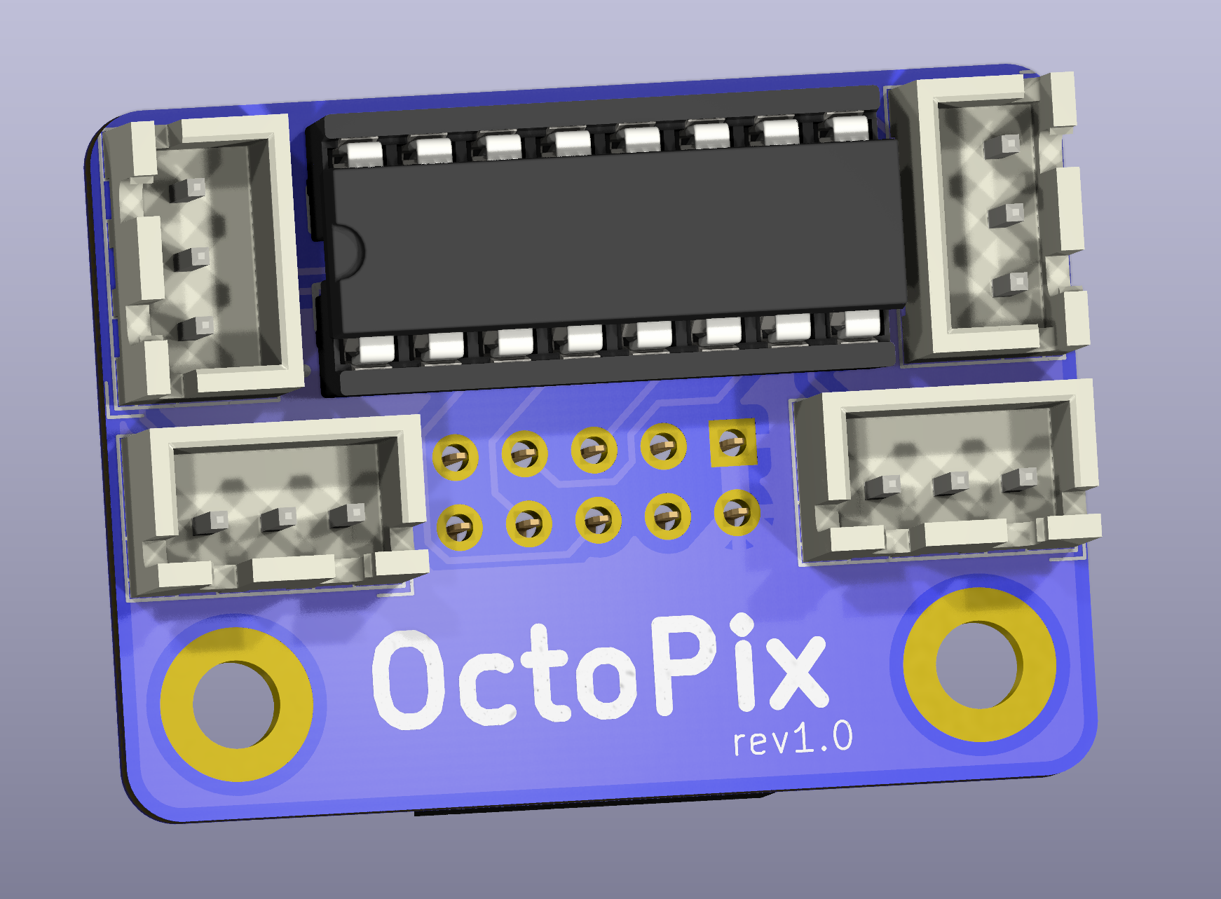
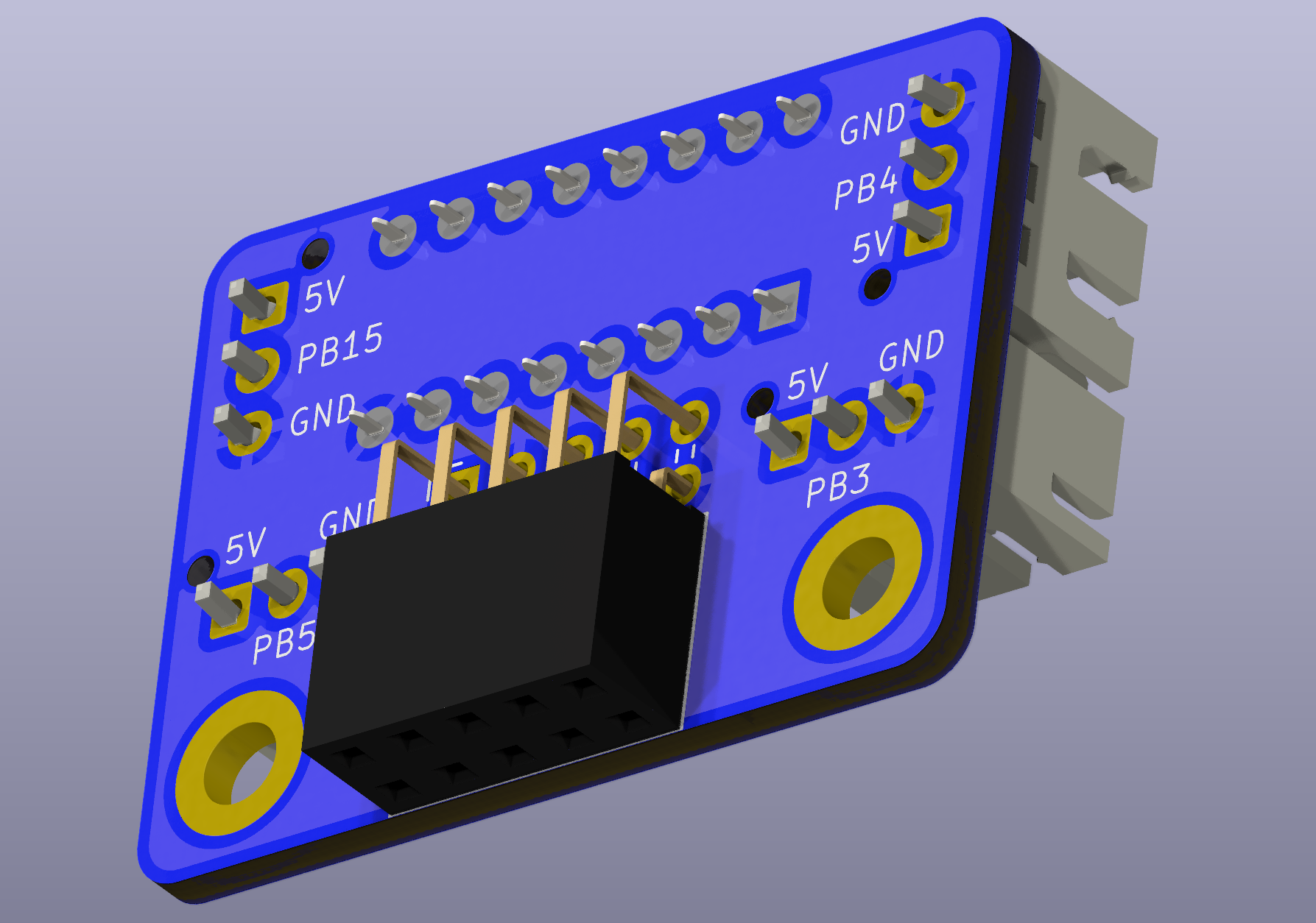
This PCB expansion board adds additional Neopixel outputs to your BTT Octopus board, allowing for custom RGB lighting configurations. It plugs into the Octopus's SPI3 header (J47) and provides four JST-XH 3-pin connectors to support up to four separate Neopixel connections.
| Quantity | Part Description | Example Sourcing Links |
|---|---|---|
| 4 | JST-XH 3-pin connectors | DigiKey |
| 1 | 2x5 header, 2.54mm pitch (Sullins SFH11-PBPC-D05-RA-BK) | DigiKey SFH11-PBPC-D05-RA-BK |
| 1 | CD4050B (DIP 16 package) | DigiKey |
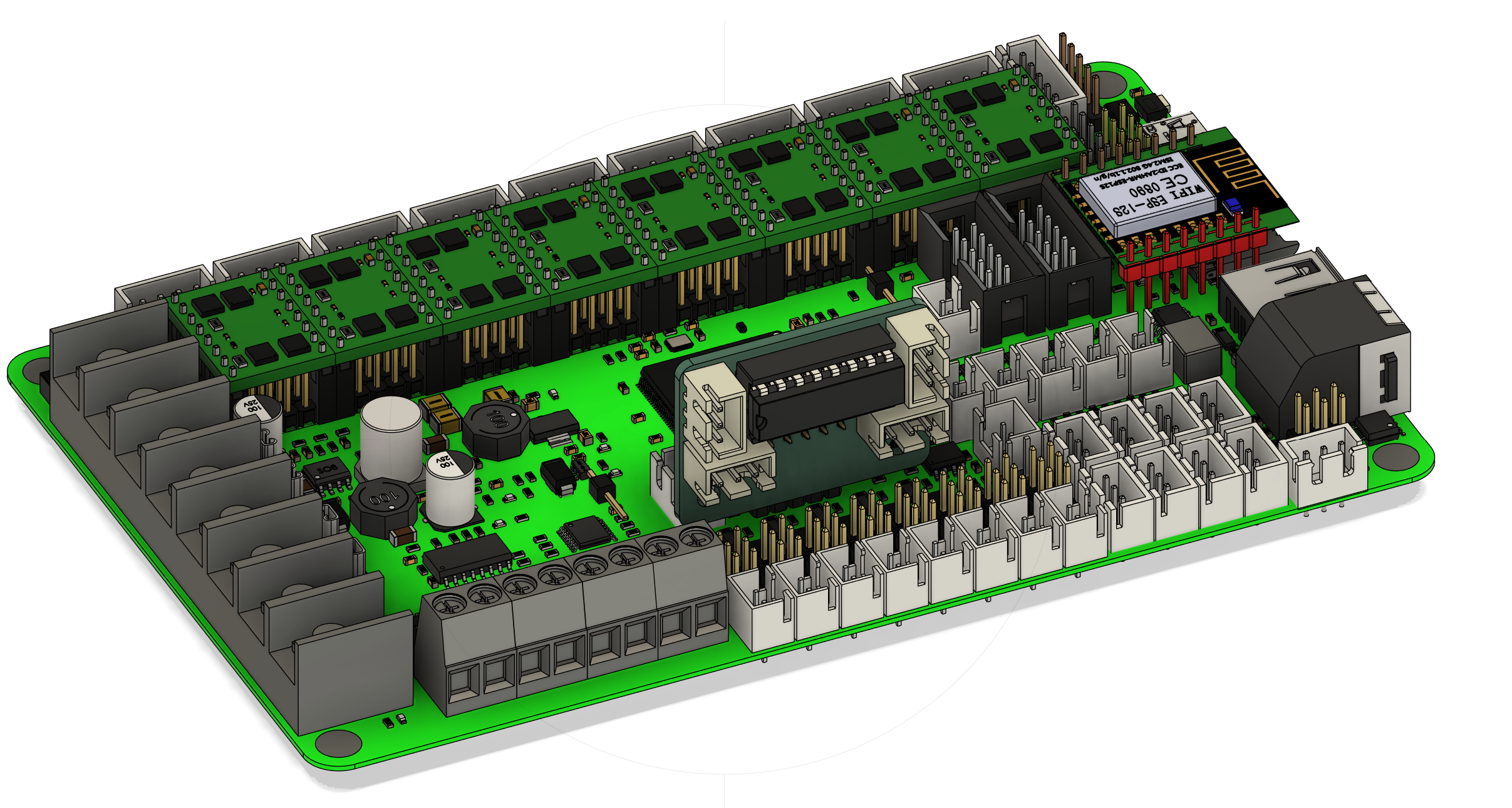
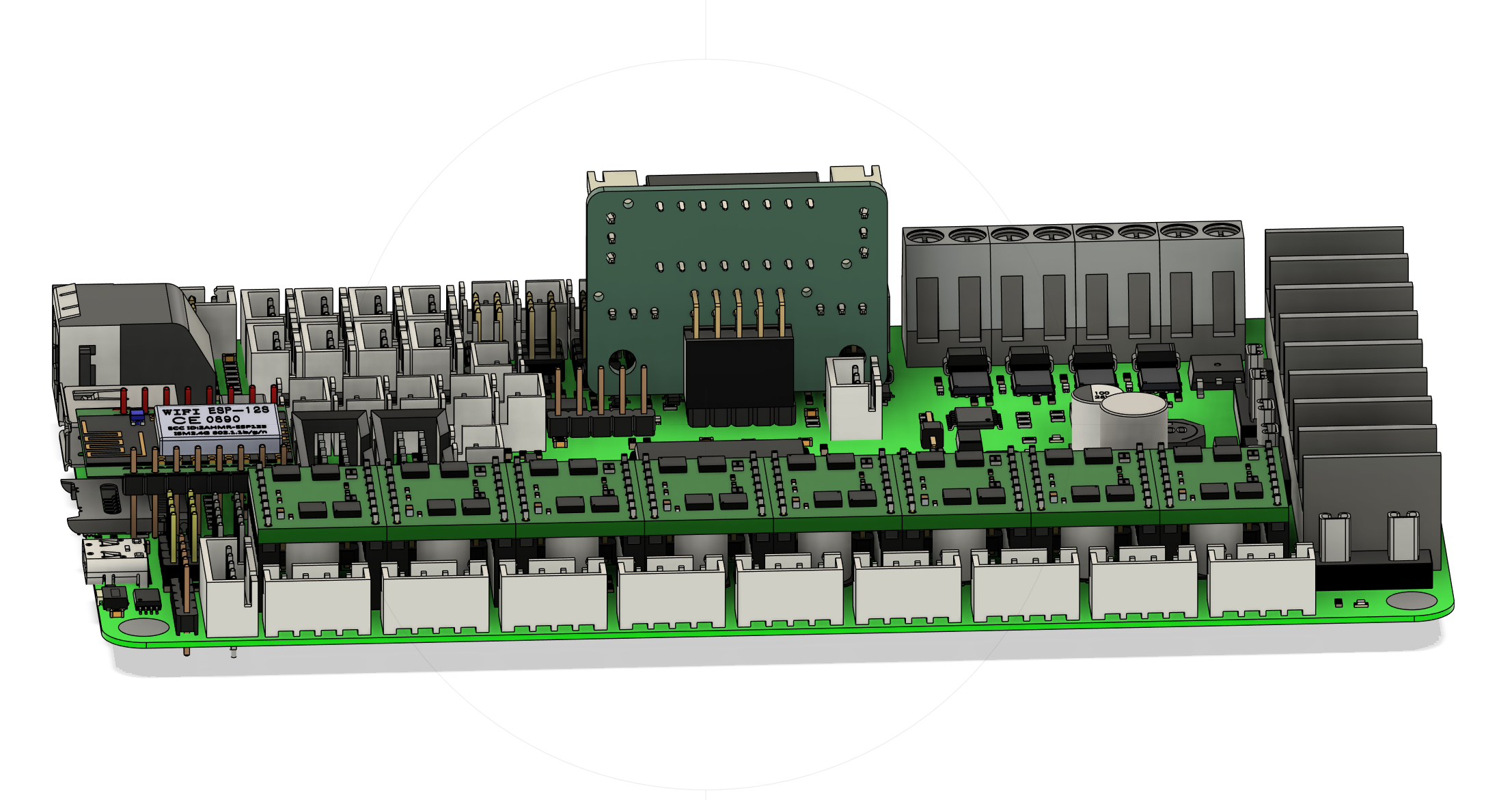
OctoPix PCB Installed on BTT Octopus Board (front and rear views):
Some users have reported the isssue that when assigning PB3, PB4, and PB5 to neopixels, klipper reports the pins as already being assigned to spi3 (specially in STM32F446 MCUs).
If you get this problem when restarting klipper, the solution is to recompile klipper firmware commenting out the lines below, found in the source code under ~/klipper/src/stm32/spi.c:
 DECL_ENUMERATION("spi_bus", "spi3", 4);
 DECL_CONSTANT_STR("BUS_PINS_spi3", "PB4,PB5,PB3");
The lines should instead read:
//DECL_ENUMERATION("spi_bus", "spi3", 4);
//DECL_CONSTANT_STR("BUS_PINS_spi3", "PB4,PB5,PB3");
After re-compiling and flashing the Octopus, PB3, PB4, and PB5 should be free to be used as GPIO pins instead of being bound to spi3
This project was created by knight_rad.iant on Discord. Join the discussion and follow updates on the design.
Contributions, suggestions, and improvements are welcome. Please open an issue or submit a pull request if you have ideas to enhance this project.
| Qty | Value | Footprint | References |
|---|---|---|---|
| 2 | MountingHole | MountingHole:MountingHole_3.2mm_M3_DIN965_Pad | H1, H2 |
| 1 | CD4050BE | easyeda:DIP-16_L20.3-W10.2-P2.54-LS10.2-BL | U1 |
| 1 | Octopus SPI3 | Connector_PinSocket_2.54mm:PinSocket_2x05_P2.54mm_Horizontal | J6 |
| 1 | RBG PB3 | Connector_JST:JST_XH_B3B-XH-AM_1x03_P2.50mm_Vertical | J2 |
| 1 | RBG PB4 | Connector_JST:JST_XH_B3B-XH-AM_1x03_P2.50mm_Vertical | J3 |
| 1 | RBG PB5 | Connector_JST:JST_XH_B3B-XH-AM_1x03_P2.50mm_Vertical | J4 |
| 1 | RBG_PB3 | Connector_JST:JST_XH_B3B-XH-AM_1x03_P2.50mm_Vertical | J5 |
It measures 25.8 × 35.5 mm and has 2 copper layers, 1.6 mm thick.
8 parts, built around the CD4050BE. The full list of its parts is on this page, with links to each part's symbol and footprint where PCBKit's library has them.
From the jrlomas/OctoPix repository on GitHub, at the commit this page was made from: the board is KiCad/octopixel.kicad_pcb and its schematic KiCad/octopixel.kicad_sch. PCBKit opens the board in the browser, with nothing to install.
Its repository publishes it under the MIT licence: you may reuse it on that licence's terms (keep the author's notice, and for a copyleft licence share your changes alike).

koolcat6666/Engine-Simulator-2.0
Engine simulator for ECU testing based on ESP32-32U DevKitC. The system connects to the ECU through the standard Speeduino 40-pin IDC connector and generates signals to simulate real engine operation.

shareresearchteam/SAMI-Robot
Software and Hardware resources and development of the SAMI humanoid robot


joeycastillo/Sensor-Watch
A board replacement for the classic Casio F-91W wristwatch

rusefi/rusefi
rusefi - GPL internal combustion engine control unit

hoglet67/RGBtoHDMI
Bare-metal Raspberry Pi project that provides pixel-perfect sampling of Retro Computer RGB/YUV video and conversion to HDMI