2 layers142.6 × 85.1 mm
LineFollower Speedy-
Club-robotica-UDLSB/LineFollower-Speedy-
Documentación del desarrollo del Seguidor de línea (El speedy)
89 partsGPL-3.0

 kev-m/DFC77
A personal project to generate a local DCF77-compatible signal for nearby radio-controlled clocks.
DFC77 ESP01 is an open-source printed circuit board by kev-m, from the kev-m/DFC77 repository on GitHub. It is a 2-layer board with 19 parts on 23 nets, routed with 85 tracks and 0 vias.
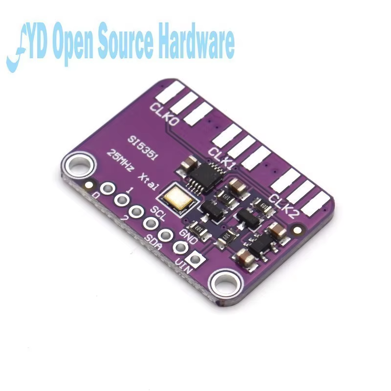
It is built around the ESP-01S, AMS1117-3.3 and SI5351A-B-GT, with the C1815 and S8050 among its other parts. Its parts include 5 capacitors, 3 ICs, 2 transistors, 2 connectors and 2 inductors. It belongs with the radio and wireless and lEDs and displays boards and the ESP8266 boards of this library.


A personal project to generate a local DCF77-compatible signal for radio-controlled clocks at home.
I live in Slovenia, far from Frankfurt, so my clocks rarely receive the original DCF77 broadcast reliably.
This project solves that by retransmitting a local signal indoors.
DCF77 reception can be unreliable in my location. Instead of constantly resyncing clocks manually, I built a small local transmitter that gives all clocks in the house a strong, stable signal.
This repository contains two transmitter approaches:
I started with the software implementation first because I was impatient and did not want to wait for shipping.
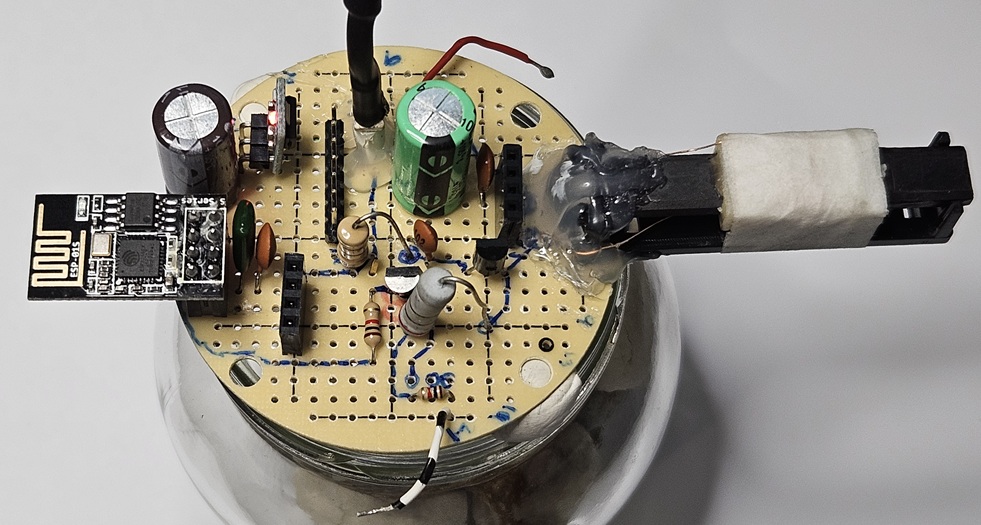
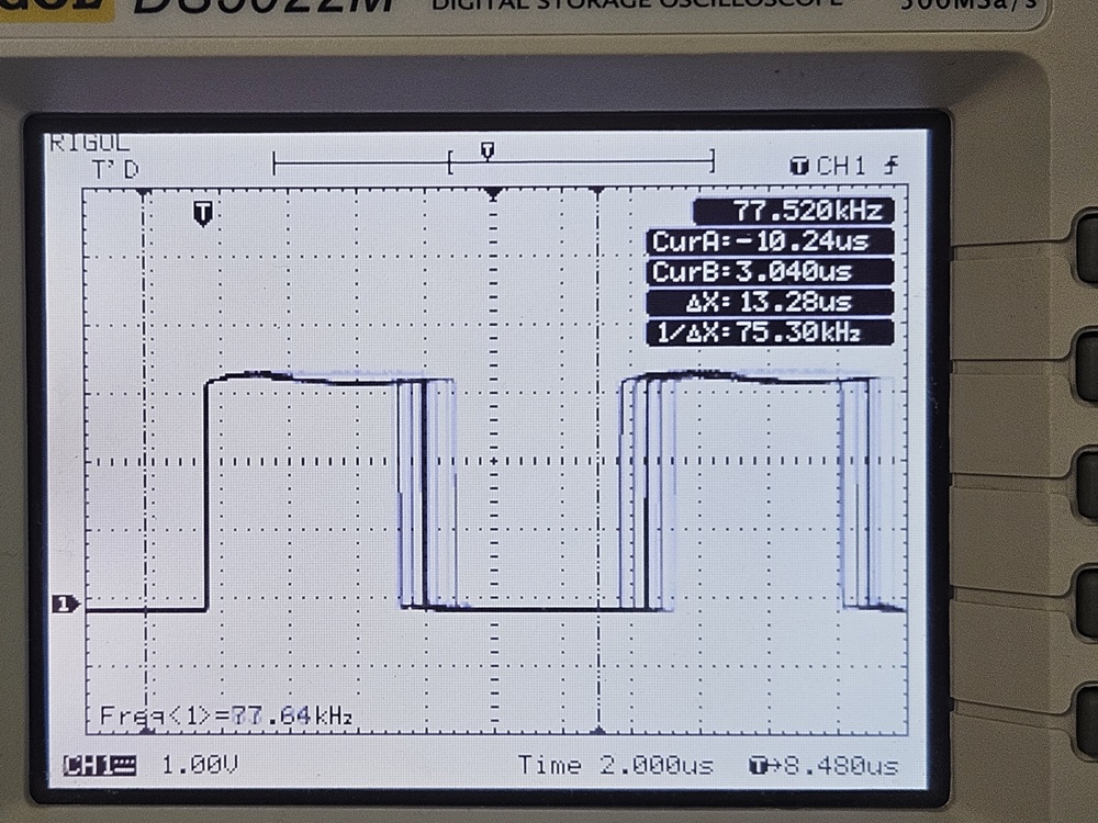
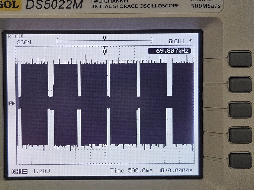
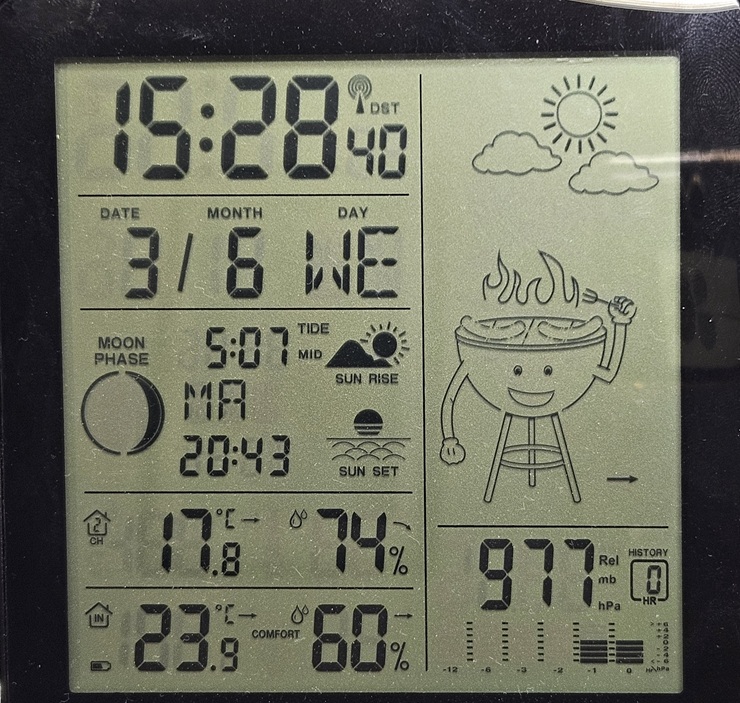
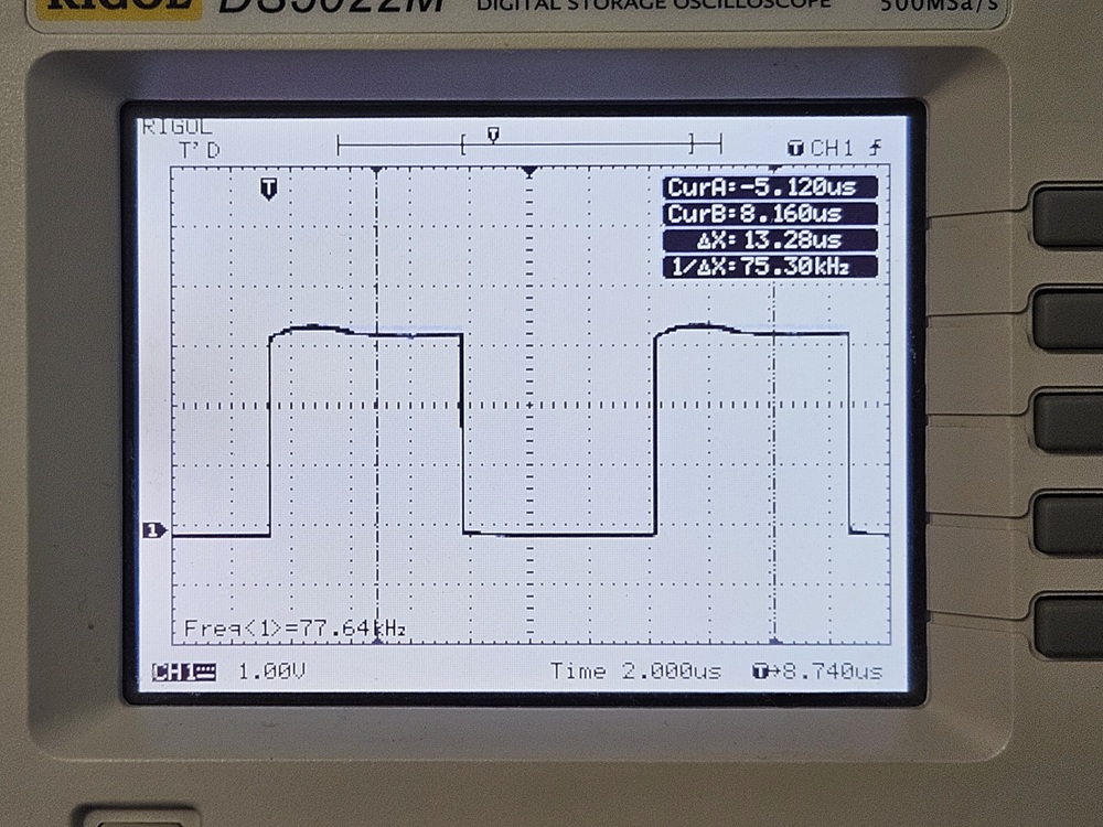
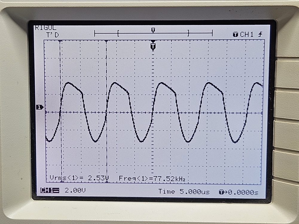
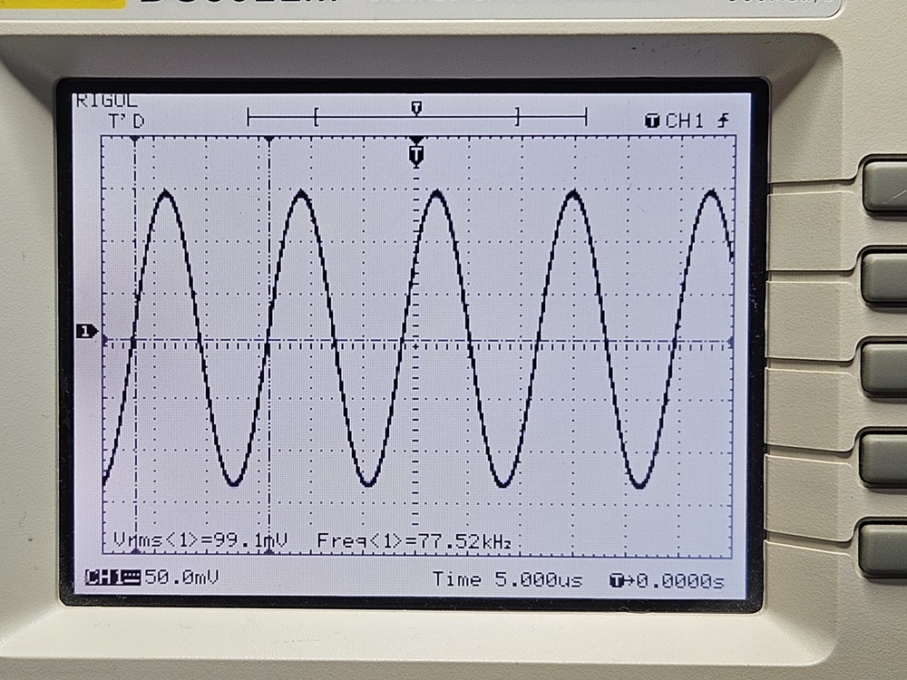
Final tuning required moving the primary and secondary coils for optimum resonance and power transfer.
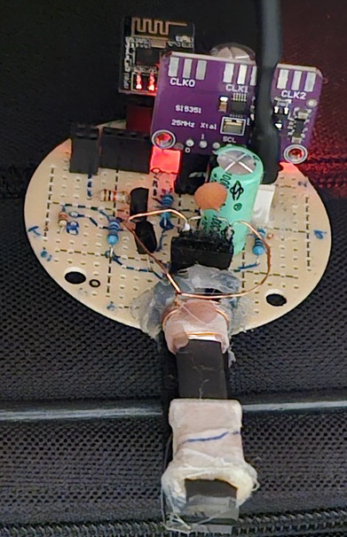
This project is intended for private, low-power experimentation in a controlled local environment. Radio transmission rules vary by country. Before building or operating a DCF77-like transmitter, check and follow your local telecom/radio regulations.
Working and deployed at home, supports:
| Qty | Value | Footprint | References |
|---|---|---|---|
| 2 | 100nF | Capacitor_THT:C_Disc_D7.0mm_W2.5mm_P5.00mm | C3, C4 |
| 2 | 1kΩ | Resistor_THT:R_Axial_DIN0204_L3.6mm_D1.6mm_P7.62mm_Horizontal | R_Base_Q2, R_Mod1 |
| 1 | 1000µF | Capacitor_THT:CP_Radial_D8.0mm_P3.50mm | C2 |
| 1 | 1000µF | Capacitor_THT:CP_Radial_D10.0mm_P5.00mm | C1 |
| 1 | 10Ω | Resistor_THT:R_Axial_DIN0204_L3.6mm_D1.6mm_P7.62mm_Horizontal | R_Iso1 |
| 1 | 4.7Ω | Resistor_THT:R_Axial_DIN0204_L3.6mm_D1.6mm_P7.62mm_Horizontal | R_Degen1 |
| 1 | 470Ω | Resistor_THT:R_Axial_DIN0204_L3.6mm_D1.6mm_P7.62mm_Horizontal | R_Base_Q1 |
| 1 | AMS1117-3.3 | Connector_PinHeader_2.54mm:PinHeader_1x03_P2.54mm_Vertical | U1 |
| 1 | Antenna_Primary | Inductor_THT:L_Radial_D12.0mm_P5.00mm_Fastron_11P | L1 |
| 1 | Antenna_Secondary | Inductor_THT:L_Radial_D12.0mm_P5.00mm_Fastron_11P | L2 |
| 1 | C1815 | Package_TO_SOT_THT:TO-92_Inline | Q2 |
| 1 | Debug | Connector_PinSocket_2.54mm:PinSocket_1x05_P2.54mm_Vertical | J2 |
| 1 | ESP-01S | Connector_PinSocket_2.54mm:PinSocket_2x04_P2.54mm_Vertical | U2 |
| 1 | Matched | Capacitor_THT:C_Disc_D10.0mm_W2.5mm_P5.00mm | C5 |
| 1 | PWR_5V | Connector_PinHeader_2.54mm:PinHeader_1x02_P2.54mm_Vertical | J1 |
| 1 | S8050 | Package_TO_SOT_THT:TO-92_Inline | Q1 |
| 1 | Si5351A | Connector_PinHeader_2.54mm:PinHeader_1x07_P2.54mm_Vertical | U3 |
19 parts, built around the ESP-01S, AMS1117-3.3, SI5351A-B-GT and C1815. The full list of its parts is on this page, with links to each part's symbol and footprint where PCBKit's library has them.
From the kev-m/DFC77 repository on GitHub, at the commit this page was made from: the board is KiCAD/DFC77_ESP01/DFC77_ESP01.kicad_pcb and its schematic KiCAD/DFC77_ESP01/DFC77_ESP01.kicad_sch. PCBKit opens the board in the browser, with nothing to install.
Its repository states no licence, so its author keeps all rights: ask kev-m before reusing the design.
Club-robotica-UDLSB/LineFollower-Speedy-
Documentación del desarrollo del Seguidor de línea (El speedy)

Ennar1991/TasmotaLED
Simple 12V LED strip driver based on ESP-01S board running Tasmota


Blackcastus/ESP32_A7670
To make it easy for you to get started with GitLab, here's a list of recommended next steps.


peakhunt/chinese-diesel-heater-black-pill
stm32f4 based chinese diesel heater