2 layers55.4 × 66 mm

 kanengomibako/EffectsPedals14
BootsUpBuffer is an open-source printed circuit board by kanengomibako, from the kanengomibako/EffectsPedals repository on GitHub, published under the Unlicense licence. It is a 2-layer board of 33 × 40 mm with 38 parts on 22 nets, routed with 159 tracks and 2 vias.
It is built around the TL072, NE555N and BAT43, with the B10K among its other parts. Its parts include 15 resistors, 11 capacitors, 5 connectors, 3 diodes and 2 ICs.


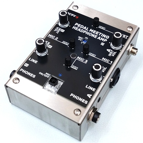
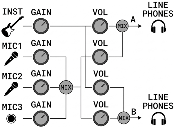
エフェクター展示会の試奏ブースでのコミュニケーションを円滑にするために設計されたヘッドフォンアンプです。ギター/ベースの音と会話用のマイク音声をミックスし、ヘッドフォンで聴くことができます。試奏者と出展者が音を共有できると共に、ヘッドフォンを外さずに会話することが可能となります。
※ 電源は、DC9V(センターマイナス)出力のACアダプターで、0.3A以上の電流出力が可能なものを使用してください。
それぞれ独立したゲイン調整を備えています。ゲインを上げ過ぎるとハウリングが起こることがありますのでご注意ください。
INST
楽器側の音声出力を接続します。アンプ・キャビネットシミュレータからの接続を想定しています。ゲインは基本的に中央で固定し、微調整として使用してください。
MIC1/MIC2
外部マイクを接続します。48Vファンタム電源が必要なマイクには対応していません。
MIC3
本体トップ面にあるマイクです。外部マイクがない場合でも、会話を拾うことが可能です。
楽器の音とマイクの音をそれぞれ出力ボリュームで調整できます。
PHONES A/B
試奏者用、出展者用のヘッドフォンを接続します。
LINE A/B
外部録音機器を接続できます。
MIC ON/OFF
すべてのマイク入力を一括でミュートします。マイクが楽器の生音を拾うため、会話時以外はマイクをOFF(LED消灯)にすることをお勧めします。
MIC 5V
プラグインパワー方式のコンデンサーマイク(BEHRINGER BC LAV 等)を使用する際にONにします。ダイナミックマイク接続時はOFFにします。48Vファンタム電源が必要なマイクには対応していません。
| ■ 主な仕様 | |
|---|---|
| 入力インピーダンス | 47kΩ(INST) 10kΩ(MIC) |
| 出力インピーダンス | 1 kΩ(LINE) 10Ω(PHONES) |
| 最大出力レベル | 2.5 Vrms(LINE) 50 mW + 50 mW, 32Ω(PHONES) |
| コントロール | MIC ON/OFFスイッチ MIC 5Vスイッチ GAINつまみ × 4 VOLつまみ × 4 |
| インジケーター | 赤色LED(電源ON) 青色LED(マイクON) |
| 接続端子 | INST MIC1/2 PHONES A/B LINE A/B 電源入力端子 |
| 消費電流 | 40 mA(無信号時) 300 mA(最大出力時) |
| 外形寸法 | 幅 100 mm × 奥行 130 mm × 高さ 57 mm |
| 質量 | 550 g |
| Qty | Value | Footprint | References |
|---|---|---|---|
| 5 | 10k | myFoot:my_R_P7mm_Horizontal | R4, R6, R7, R8, R11 |
| 3 | 100k | myFoot:my_R_P7mm_Horizontal | R2, R10, R15 |
| 3 | 10u | myFoot:my_C_D5.0mm_P2.50mm | C3, C5, C10 |
| 3 | 1k | myFoot:my_R_P7mm_Horizontal | R3, R5, R9 |
| 3 | 1u | myFoot:my_C_Disc_P2.50mm | C6, C7, C8 |
| 2 | 100p | myFoot:my_C_Disc_P2.50mm | C4, C11 |
| 2 | BAT43 | myFoot:my_D_P7.62mm | D2, D3 |
| 2 | GND | myFoot:my_WirePad_1mmDrill | J2, J4 |
| 1 | (4.7M) | myFoot:my_R_P7mm_Horizontal | R1 |
| 1 | (VR1) | myFoot:my_trim | * |
| 1 | 100R | myFoot:my_R_P7mm_Horizontal | R13 |
| 1 | 100u | myFoot:my_C_D5.0mm_P2.50mm | C9 |
| 1 | 1N4007 | myFoot:my_D_P7.62mm | D1 |
| 1 | 1u | myFoot:my_C_D5.0mm_P2.50mm_long | C1 |
| 1 | 2.2n | myFoot:my_C_Rect1_P5.00mm | C2 |
| 1 | 47k | myFoot:my_R_P7mm_Horizontal | R12 |
| 1 | 82k | myFoot:my_R_P7mm_Horizontal | R14 |
| 1 | B10k | myFoot:my_pot_5mm | VR1 |
| 1 | IN | myFoot:my_WirePad_1mmDrill | J1 |
| 1 | NE555N | Package_DIP:DIP-8_W7.62mm_Socket | U2 |
| 1 | OUT | myFoot:my_WirePad_1mmDrill | J3 |
| 1 | TL072 | Package_DIP:DIP-8_W7.62mm_Socket | U1 |
| 1 | VCC | myFoot:my_WirePad_1mmDrill | J5 |
It measures 33 × 40 mm and has 2 copper layers, 1.6 mm thick.
38 parts, built around the TL072, NE555N, BAT43 and B10K. The full list of its parts is on this page, with links to each part's symbol and footprint where PCBKit's library has them.
From the kanengomibako/EffectsPedals repository on GitHub, at the commit this page was made from: the board is BootsUpBuffer/BootsUpBuffer.kicad_pcb. PCBKit opens the board in the browser, with nothing to install.
Its repository publishes it under the Unlicense licence: you may reuse it on that licence's terms (keep the author's notice, and for a copyleft licence share your changes alike).


MCMarcusAntony/iBOLIT-1.5
Tools added to this board are: - Logic probe included on Top three pin connector. - Lighting and acoustic signals to identify HIGH and LOW status.


karolzmijewski/8bit-comp
Currently, the project is in the process of migrating from Eagle, which is no longer available for free for non-commercial use, to KiCad (an open-source PCB design and electronics CAD software).


