2 layers25.1 × 5.6 mm

 kajusK/Darkstar-Mk.II7
High-power bomb-proof headlamp for caving
Headlamp is an open-source printed circuit board by kajusK, from the kajusK/Darkstar-Mk.II repository on GitHub. It is a 2-layer board with 60 parts on 37 nets, routed with 658 tracks and 25 vias.
It is built around the ATTINY841-SSU, TSV912AID and ZXGD3001E6TA, with the MCP6567M/TR, BAT60AE6327HTSA1 and DMP2035U among its other parts. Its parts include 26 resistors, 9 capacitors, 6 diodes, 5 ICs and 4 transistors. It belongs with the AVR (ATmega, ATtiny) boards of this library.


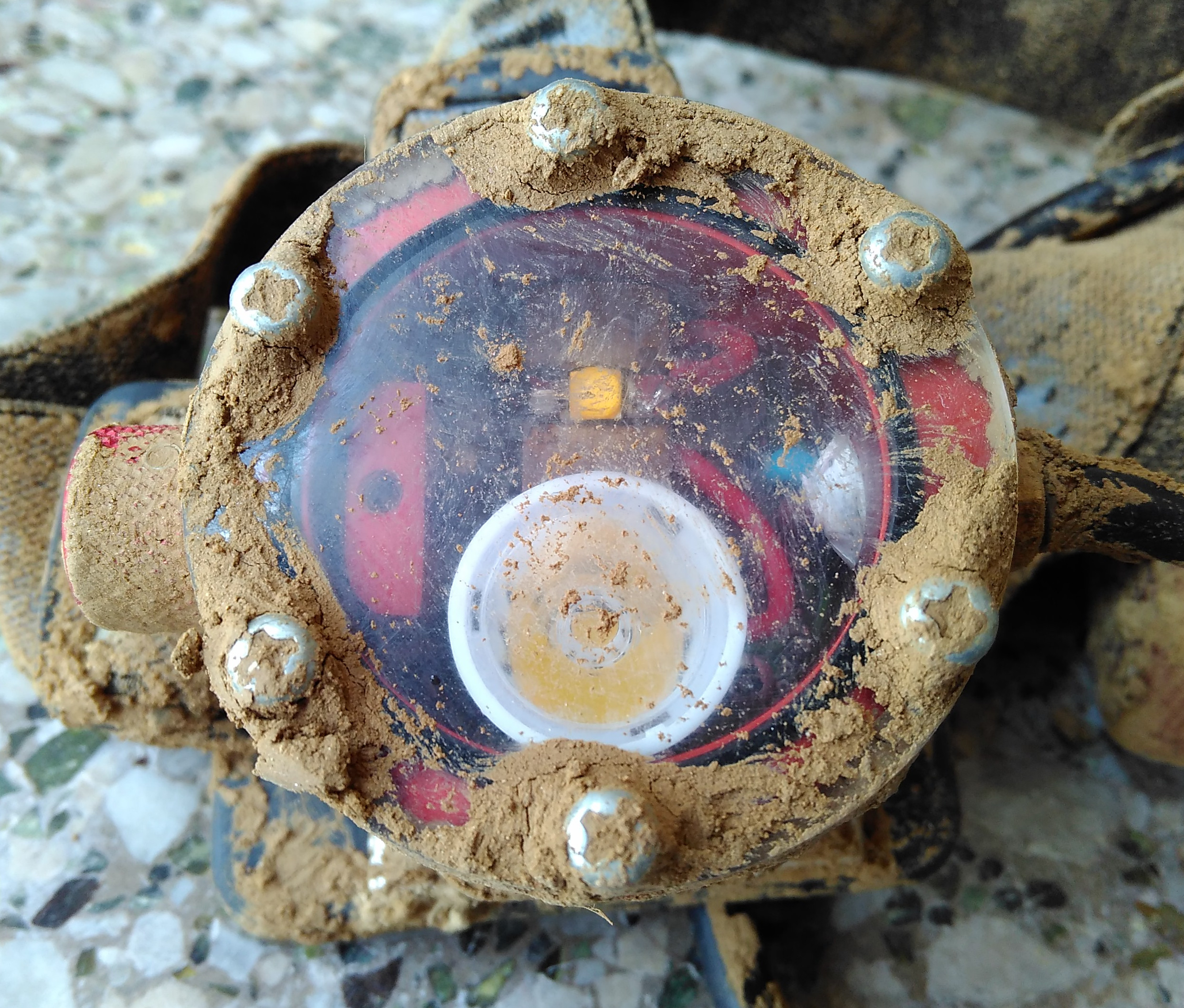
Small lightweight, water/mud/shock/bomb proof headlamp with bat roasting light output and Scurion like body for 1/8 of the price. If you are caver, mine explorer, biker, etc. with hacker soul, this is a way to go!
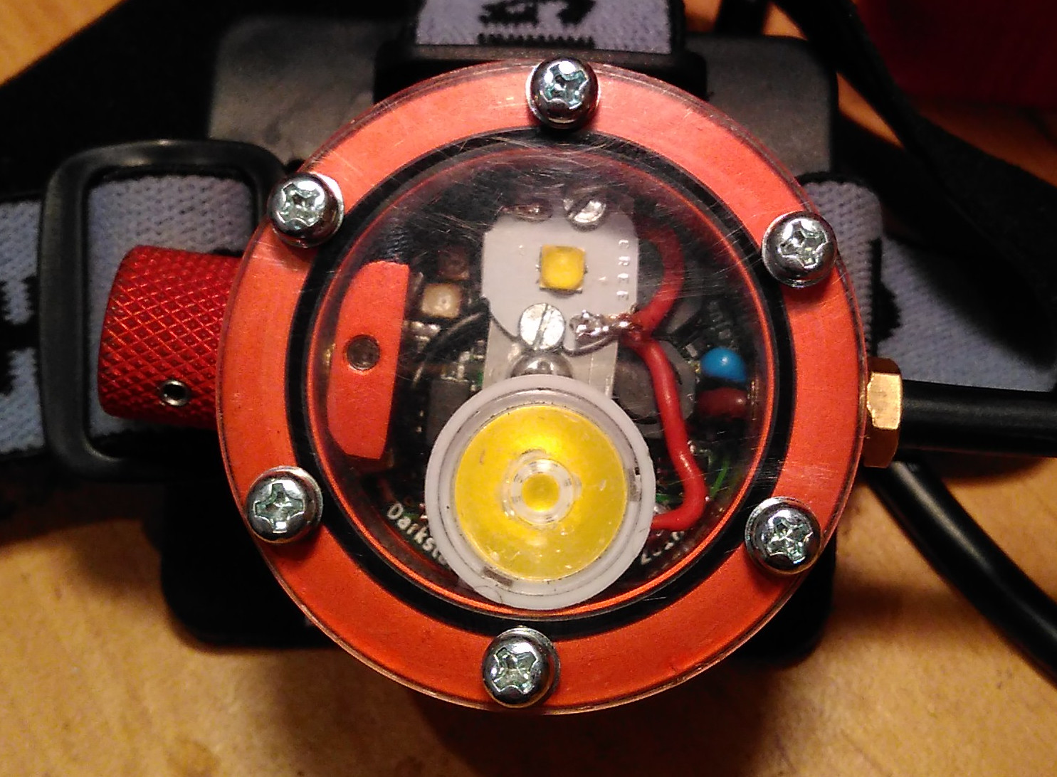

The LED drivers were custom designed from elementary components, no integrated LED solution was used. It's based on hystersis driven buck converter with current feedback.
The current is sensed by 0,056 ohm resistor, voltage across this resistor is amplified by opamp and fed to the comparator. The comparator is a brain of the driver. When the measured voltage is higher than reference voltage generated by MCU, comparator turns the MOSFET off, current drops below hystersis, MOSFET is turned on and the cycle repeats. Nothing fancy, but quite simple and cheap. Only few parts are required and measured efficiency is reaching 96 %. Over 90 % for currents over 0,5 A for whole supply voltage range allowed. Check Measurement for more details. The maximal current allowed is 2 Amps. It should be possible to get much higher currents by choosing better (bigger and more expensice) inductors and transistors.
Disadvantage of such design is a limited lowest possible current, it can't go below half of the hystersis current. For this reason 10-100 % output is constant current driven, 0-10 % is controlled by additional PWM.
The brain of the lamp is Attiny 841, it handles key presses, reference voltage generating, etc. To make it simpler to program I use optiboot arduino compatible bootloader though there is no arduino code included in the project except the bootloader itself.
To make it simpler to write your own control modes, most of the code is just a library controlling the hardware and providing few quite low level functions to user. It takes care of reading buttons, generating reference voltages for LED drivers, etc.
It also contains automated light control (PI regulator). The light is measured by phototransistor and the difference between the measured value and value required is run through the PI regulator. Result is the applied to reference voltage generator. This feature is quite EXPERIMENTAL and doesn't work well for caving when the lamps gets covered in mud.
The rest is the user mode. Check simple mode to see how simple it can get. All relevant header are included. See HowTo for more details on programming and stuff.
The caving mode controls are described in User guide.
The body is machined on a lathe from 6063 aluminium alloy. No fancy expensive tools except lathe and drill press are required to make the lamp.
Top cover is made from polycarbonate sheet, cable and control rods bushings are made from brass. The whole thing is sealed with O-rings. See the BOM for more details.
The battery box is designed to be printed on any 3D printer. I would suggest using ABS and painting the resulting print with ABS juice to get is as waterproof as possible.
the wide beam led can be used without lenses, the beam is wide enough for my needs, for the narrow beam led you can buy any compatible lens that fits inside the body. I used [17mm 10deg lens] (http://www.aliexpress.com/item/free-shipping-cree-xp-g-lens-diameter-17mm-smooth-surface-with-stand-condenser-lenses-10-deg/777222733.html)
The source code is licenced under GNU GPL v2. The mechanical and electrical design is licensed under CERN OHL v.1.2.
| Qty | Value | Footprint | References |
|---|---|---|---|
| 7 | 10k | Resistors_SMD:R_0603 | R2, R3, R6, R8, R9, R12, R13 |
| 5 | 1u | Capacitors_SMD:C_0603 | C2, C4, C6, C7, C8 |
| 4 | 1k | Resistors_SMD:R_0603 | R16, R17, R24, R25 |
| 3 | 10n | Capacitors_SMD:C_0603 | C5, C9, C10 |
| 3 | 220 | Resistors_SMD:R_0603 | R4, R10, R11 |
| 2 | 0R056 | Resistors_SMD:R_1206 | R14, R15 |
| 2 | 10u | Inductors:Inductor_Bourns-SRU8043 | L1, L2 |
| 2 | 12k | Resistors_SMD:R_0603 | R20, R21 |
| 2 | 18k | Resistors_SMD:R_0603 | R18, R19 |
| 2 | 270k | Resistors_SMD:R_0603 | R22, R23 |
| 2 | 8k2 | Resistors_SMD:R_0603 | R1, R7 |
| 2 | BAT60AE6327HTSA1 | Diodes_SMD:SOD-323 | D4, D5 |
| 2 | DMP2035U | TO_SOT_Packages_SMD:SOT-23 | Q3, Q4 |
| 2 | LED | custom:Custom_Conn_2_Big | D6, D7 |
| 2 | ZXGD3001E6 | TO_SOT_Packages_SMD:SOT-23-6 | U1, U2 |
| 1 | 100k | Resistors_SMD:R_0603 | R5 |
| 1 | 10u | Capacitors_SMD:C_0603 | C1 |
| 1 | 33 | Resistors_SMD:R_0603 | R26 |
| 1 | ATTINY841-SSU | Housings_SOIC:SOIC-14_3.9x8.7mm_Pitch1.27mm | IC1 |
| 1 | BT1 | Buttons_Switches_SMD:SW_SPST_FSMSM | SW2 |
| 1 | BT2 | Buttons_Switches_SMD:SW_SPST_FSMSM | SW1 |
| 1 | ISP | TO_SOT_Packages_SMD:SOT-23-6 | P3 |
| 1 | MCP6567 | Housings_SSOP:MSOP-8_3x3mm_Pitch0.65mm | U4 |
| 1 | NX2301P | TO_SOT_Packages_SMD:SOT-23 | Q2 |
| 1 | POWER | custom:Custom_Conn_2_Big | P1 |
| 1 | RED | LEDs:LED_PLCC-2 | D2 |
| 1 | SERIAL | Connectors:GS3 | P2 |
| 1 | TSV912 | Housings_SSOP:MSOP-8_3x3mm_Pitch0.65mm | U3 |
| 1 | VEMT3700-GS08 | LEDs:LED_PLCC-2 | Q1 |
| 1 | WHITE | LEDs:LED_PLCC-2 | D3 |
The 57 most common of 60 parts.


Miceuz/paper-wifi
Low power E-paper display devboard with WiFi and BLE connectivity. Open source hardware.


60 parts, built around the ATTINY841-SSU, TSV912AID, ZXGD3001E6TA and MCP6567M/TR. The full list of its parts is on this page, with links to each part's symbol and footprint where PCBKit's library has them.
From the kajusK/Darkstar-Mk.II repository on GitHub, at the commit this page was made from: the board is pcb/headlamp/headlamp.kicad_pcb. PCBKit opens the board in the browser, with nothing to install.
Its repository states no licence, so its author keeps all rights: ask kajusK before reusing the design.