Skip to the content
4 layers72 × 90 mmCoilTile, the printed circuit board in 3D

KiCad extension for the copper you can't buy as a part — design planar inductors, transformers, PCB motor stators, filters, and antennas, with electrical modeling and direct write-back to your board.

Size
72 × 90 mm
Copper layers
4
Thickness
1.6 mm
Parts
32
Nets
27
Pads
114
Tracks, vias
215, 62
Pours
3
Routed
Yes
KiCad
KiCad 9.0 (file 20241229)
Created
7 Sep 2026
Updated
20 Oct 2026

Overview

CoilTile is an open-source printed circuit board by jonahsaunders, from the jonahsaunders/planar-studio repository on GitHub, published under the MIT licence. It is a 4-layer board of 72 × 90 mm with 32 parts on 27 nets, routed with 215 tracks and 62 vias.

It is built around the LDC1614RGHR, MCP2221A-I/ST and AP2112K-3.3TRG1, with the USBLC6-2SC6, 0603CG221J500NT and CC0603KRX7R9BB104 among its other parts. Its parts include 10 capacitors, 5 resistors, 4 ICs, 4 inductors and 1 connector. It belongs with the radio and wireless and robots and motor control boards of this library.

Main components

8

README

README.md

Planar Studio

installer KiCad 9.0.1+ MIT license

Design planar inductors, transformers, PCB motors, filters and antennas inside KiCad. Planar Studio reads your board's stack, calculates electrical estimates, and places the generated copper into the PCB as one undoable operation.

Download v1.6.0 · Install · Guides · Common PCB issues · Flyback example · GaN example · CoilTile example
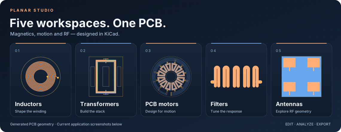
Five workspaces: inductors, transformers, PCB motors, filters and antennas

Explore the workspaces

Current application captures. Click a view to open the full-size image.

Inductors

Two parallel inductor layers with inductance, resistance and frequency-response readouts

Shape windings, connect layers and route around obstacles.
Winding guide →

Transformers

Ferrite transformer copper, winding connections and core cross-section

Build ferrite stacks, compare candidates and verify operating limits.
Transformer guide →

PCB motors

Twelve-coil rotary stator with phase phasors and motor estimates

Explore rotary, stepper, linear, dual-rotor and planar machines.
See all five motor families →

Filters

Hairpin filter geometry with calculated transmission and reflection

Turn LC and microstrip networks into copper and response plots.
Filter models →

Antennas

Patch array with element dimensions and ideal array-factor plot

Design patches, arrays, directional radiators and NFC loops.
Explore antenna layouts →

Design tools

Calculated magnetic-field map in the Design tools workspace

Inspect fields, optimize geometry and compare measurements.
Design tools guide →

Open the full 15-image gallery → — obstacle routing, transformer search, motor families, antenna variants and both interface themes.

Save editable designs, compare calculated responses, and export KiCad boards or footprints, SVG, DXF, JSON and specification sheets. The Design tools panel adds constrained searches, measurement overlays, tolerance studies and board checks; see the tools guide.

Install

The 1.6.0 development release supports KiCad 9.0.1 or newer on Windows, macOS and Linux. Release notes.

  1. Download planar-studio-1.6.0.zip and leave it zipped.
  2. In KiCad's main Project Manager, open Plugin and Content Manager.
  3. Choose Install from File, select the ZIP and apply pending changes.
  4. Restart KiCad, open the PCB Editor, and launch Planar Studio after its Python environment finishes setting up.
Upgrading or getting a metadata error?

To upgrade, close Planar Studio and the PCB Editor. In Plugin and Content Manager → Installed, uninstall the old version and apply pending changes before installing the new ZIP. Saved designs are stored separately; preserve the settings folder.

Use the installer linked above. GitHub's Code → Download ZIP and Source code archives contain the repository, not a PCM installer.

5 W planar flyback example

A10 retains the winding-short repair, increases measured turn gaps to about 0.289 mm, enlarges T1 annular rings and removes tangent secondary-via contacts. Independent geometry, connection-width and full copper/mask Gerber checks protect these changes. Use the A10 package and the common PCB issues reference when reviewing or editing the design.
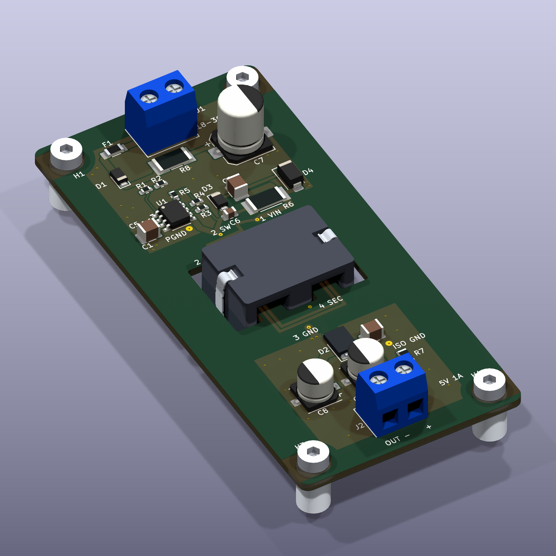
KiCad render of the assembled planar flyback converter

An 18–36 V DC to isolated 5 V / 1 A converter with an LT8302 controller and transformer windings built into a six-layer PCB. The example includes a KiCad 10 project, schematic, BOM, calculations and single-board manufacturing files for JLCPCB-managed panelization.

Unbuilt engineering prototype. Factory acceptance and electrical, thermal and magnetic qualification remain open.

Explore the board and schematic · Review package · Validation record

60 W GaN planar LLC example
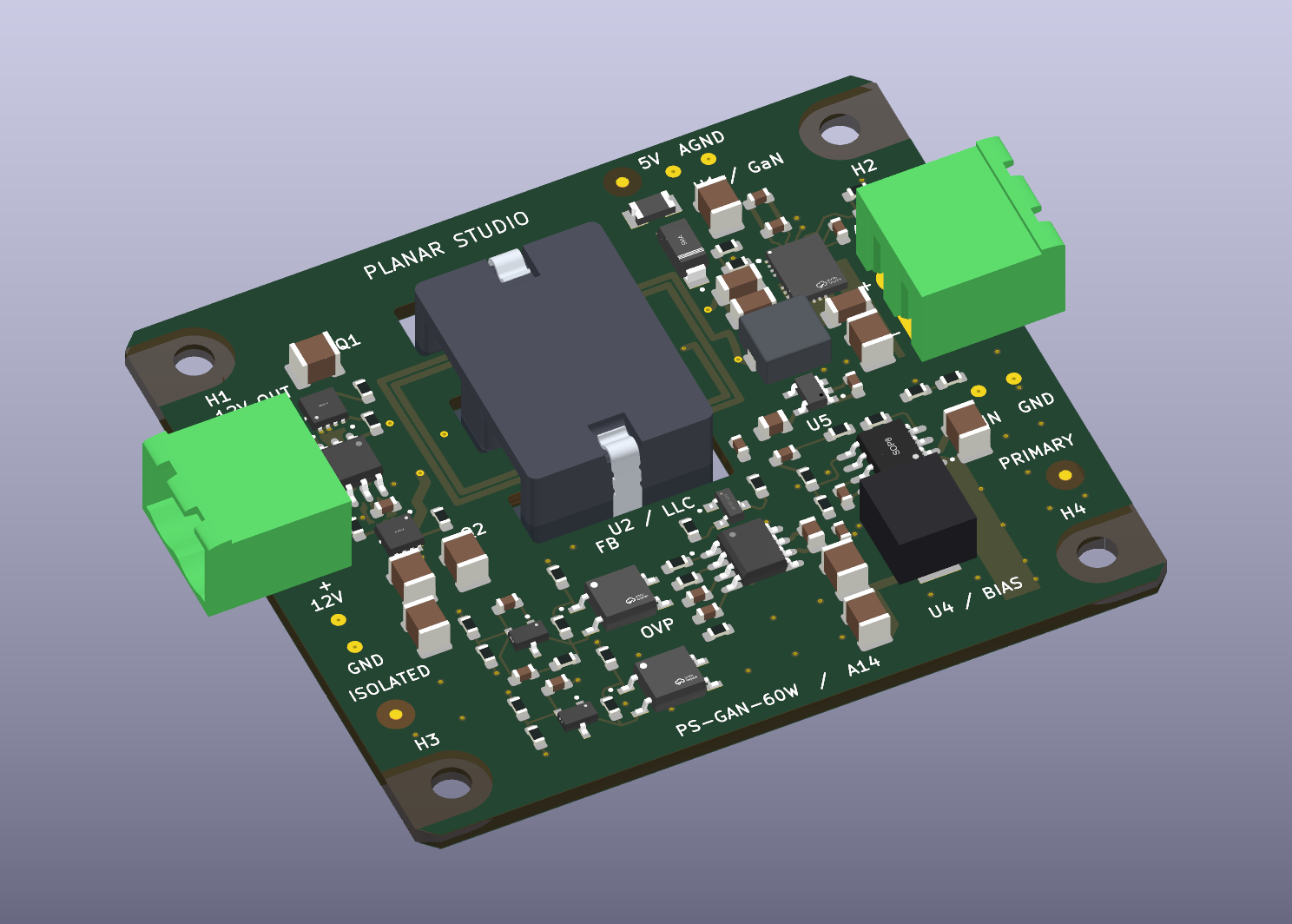
KiCad render of PS-GAN-60W with planar magnetics, removable screw-terminal ports and M3 mounting holes

A 48 V nominal to isolated 12 V / 5 A target using an integrated GaN half bridge, silicon synchronous rectifiers and an eight-layer PCB transformer. The 64 × 56 mm chamfered board has all electronics on top, removable screw-terminal ports, and the flyback example's exposed-substrate M3 hole geometry on a 55 × 47 mm pattern. The A10 schematic uses visible local wiring and has no four-way connections. The accompanying MIT PER and video studies explain the layout decisions. An 82-reference ratings audit records the corrected parts and outstanding electrical limits.

Unbuilt engineering prototype. ERC, DRC, connectivity, assembly-file agreement and a portable rebuild pass. Factory DFM, ferrite installation and electrical, magnetic and thermal qualification remain open. 60 W is not a measured result.

Manufacturing audit: do not order the current revision. The five-board review found overlapping same-net component lands, incomplete courtyards, GaN stencil/mask and placement-origin issues, and a factory stack mismatch. The audit and cost breakdown record required corrections and unconfirmed turnkey operations.

Explore the native KiCad example · KiCad package · Layout resource review · PER design study · Validation record

CoilTile USB inductive sensing example
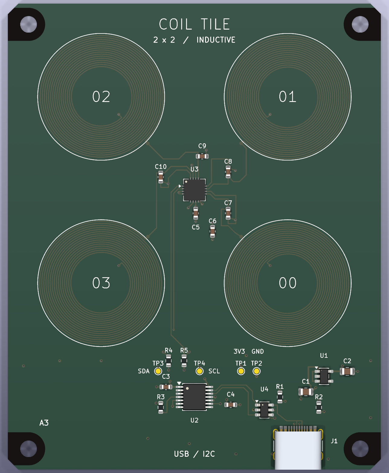
CoilTile assembled PCB layout

A 2 × 2 near-field metal-sensing array using four printed coils generated by Planar Studio, an LDC1614 converter and an MCP2221A USB bridge. The A3 schematic shows one continuous USB → I²C → sensor → LC-tank signal path. The 72 × 90 mm four-layer PCB reuses the flyback/GaN examples' exposed-substrate M3 edge holes.

Includes editable KiCad 9 files, a Python heatmap and CSV logger, an exact-code JLCPCB BOM/CPL, Gerbers, and bring-up instructions. No firmware flashing is needed. Unbuilt prototype: native ERC/DRC and connectivity checks pass; physical sensing range, crosstalk and supplier assembly acceptance remain unverified.

Explore CoilTile · Schematic PDF · A3 review · Assembly handoff

Guides

Calculated performance depends on the selected model. Review its assumptions and validate the resulting hardware with appropriate simulation, KiCad DRC and measurements. Transformer loss or thermal results that cannot be calculated are reported as unknown.

Built on planar-coil-studio. Released under the MIT license.

Parts

32
QtyValueFootprintReferences
4220pF / C0GCoilTile:C_0603_1608MetricC7, C8, C9, C10
45.51uH nominalCoilTile:Planar_24mm_16TL1, L2, L3, L4
4M3 / NPTH 3.2mmCoilTile:MountingHole_3.2mm_M3_ExposedSubstrate_EdgeH1, H2, H3, H4
2100nF / 50VCoilTile:C_0603_1608MetricC3, C5
24.7kRCoilTile:R_0603_1608MetricR4, R5
24.7uF / 25VCoilTile:C_0805_2012MetricC1, C2
2470nF / 25VCoilTile:C_0603_1608MetricC4, C6
25.1kRCoilTile:R_0603_1608MetricR1, R2
1+3V3CoilTile:TestPoint_Pad_D1.0mmTP1
110kRCoilTile:R_0603_1608MetricR3
1AP2112K-3.3TRG1CoilTile:SOT-23-5U1
1GNDCoilTile:TestPoint_Pad_D1.0mmTP2
1LDC1614RGHRCoilTile:WQFN-16-1EP_4x4mm_P0.5mm_EP2.6x2.6mmU3
1MCP2221A-I/STCoilTile:TSSOP-14_4.4x5mm_P0.65mmU2
1SCLCoilTile:TestPoint_Pad_D1.0mmTP4
1SDACoilTile:TestPoint_Pad_D1.0mmTP3
1USB-C / USB 2.0CoilTile:USB_C_Receptacle_HRO_TYPE-C-31-M-12J1
1USBLC6-2SC6CoilTile:SOT-23-6U4

More from jonahsaunders/planar-studio

2
  • 8 layers64 × 56 mmPS GAN-60W, the printed circuit board in 3D

    PS GAN-60W

    jonahsaunders/planar-studio

    KiCad extension for the copper you can't buy as a part — design planar inductors, transformers, PCB motor stators, filters, and antennas, with electrical modeling and direct write-back to your board.

    89 parts4MIT
  • 6 layers44 × 94 mmPS FLYBACK-5W, the printed circuit board in 3D

    PS FLYBACK-5W

    jonahsaunders/planar-studio

    KiCad extension for the copper you can't buy as a part — design planar inductors, transformers, PCB motor stators, filters, and antennas, with electrical modeling and direct write-back to your board.

    29 parts4MIT

Similar boards

  • 4 layers59 × 101 mmEnku mainboard r0.1, the printed circuit board in 3D

    Enku mainboard r0.1

    aliaksei-lameyka/ENKU-Base-reader

    Open enku-mainboard-r0.1.kicadpro with KiCad10.0.7. Matching PCB/root schematic and power.kicadsch, mcuio.kicadsch, epdhv.kicadsch, connectors.kicadsch are canonical.

    127 parts1CERN-OHL-W-2.0
  • 4 layers150 × 115 mmUsb controlled debug hub 2a, the printed circuit board in 3D

    Usb controlled debug hub 2a

    misko/prompt2device

    The separate vNext PCB skill and orchestrator package is available alongside the reference workflow below; existing projects keep their accepted toolchain until an explicit migration.

    190 parts3MIT
  • 2 layers40 × 110 mmFv1 module, the printed circuit board in 3D

    Fv1 module

    niektb/sluisbrinkie-eurorack-published

    Published Modules of the Sluisbrinkie project

    81 parts34
  • 4 layers119 × 63.2 mmOpenChordM1, the printed circuit board in 3D

    OpenChordM1

    FugLong/OpenChord

    An open-source music device for portable, expressive, and extensible audio creation.

    75 parts3MIT
  • 4 layers160 × 145 mmCarrier, the printed circuit board in 3D

    Carrier

    OrbitalCommons/gumstick

    Gumstick: ESP32 + iCE40UP5K FPGA module (v1 DF40 board-to-board, v2 M.2 gold-finger draft) and its programming carrier. KiCad 10.

    222 parts1MIT
  • 4 layers58 × 70 mmProbelab, the printed circuit board in 3D

    Probelab

    enkhbold470/kicad-projects

    Five KiCad 10 boards (4- and 6-layer): ESP32-S3 industrial gateway, USB-C PD bench supply, RP2040 logic analyzer, FOC motor controller, iCE40 FPGA board.

    88 partsCERN-OHL-S-2.0
  • 4 layers30 × 48 mmEsp32 mpr121, the printed circuit board in 3D

    Esp32 mpr121

    HeyPCB/esp32-sensors-2

    ESP32-S3 boards, one sensor each: KiCad 10, JLCPCB-ready, CERN-OHL-S-2.0

    27 partsCERN-OHL-S-2.0
  • 4 layers64 × 80 mmIris brainstem, the printed circuit board in 3D

    Iris brainstem

    HeyPCB/iris-brainstem

    Iris Brainstem: power and servo hub of the Iris robot head. 9 V USB-C PD in, 6 V / 5 A servo rail in stitched copper zones (measured), 5 V rail, half-duplex servo bus with ten ports, speaker amp.

    97 partsCERN-OHL-S-2.0

Questions

How big is the CoilTile PCB?

It measures 72 × 90 mm and has 4 copper layers, 1.6 mm thick.

What parts does the CoilTile use?

32 parts, built around the LDC1614RGHR, MCP2221A-I/ST, AP2112K-3.3TRG1 and USBLC6-2SC6. The full list of its parts is on this page, with links to each part's symbol and footprint where PCBKit's library has them.

Where can I download the CoilTile KiCad files?

From the jonahsaunders/planar-studio repository on GitHub, at the commit this page was made from: the board is examples/coil-tile/kicad/CoilTile.kicad_pcb and its schematic examples/coil-tile/kicad/CoilTile.kicad_sch. PCBKit opens the board in the browser, with nothing to install.

Can I use the CoilTile design in my own project?

Its repository publishes it under the MIT licence: you may reuse it on that licence's terms (keep the author's notice, and for a copyleft licence share your changes alike).