6 layers142.5 × 94.5 mm

 jmh8231-Dev/ancp
Solid Propellant Motor Document
Solid Rocket Motor Test Station ver 2.0 is an open-source printed circuit board by jmh8231-Dev, from the jmh8231-Dev/ancp repository on GitHub. It is a 6-layer board of 155 × 100 mm with 286 parts on 267 nets, routed with 1,774 tracks and 486 vias.
It is built around the AS6221-EK, CC6-1212DR-E and MCP6022-I/P, with the ADS1262IPW, FT232RL and LM2596S-3.3 among its other parts. Its parts include 114 capacitors, 92 resistors, 12 ICs, 9 diodes and 6 connectors. It belongs with the robots and motor control boards of this library.


고정추진제 로켓 모터(ANCP) 지상시험을 위한 정밀 계측·점화 제어 스테이션
고정밀 아날로그 체인(로드셀/압력/열전대), 안전 중심 점화 시퀀스, 2″ LCD(LVGL9 + SPI DMA) GUI, PC 텔레메트리 지원
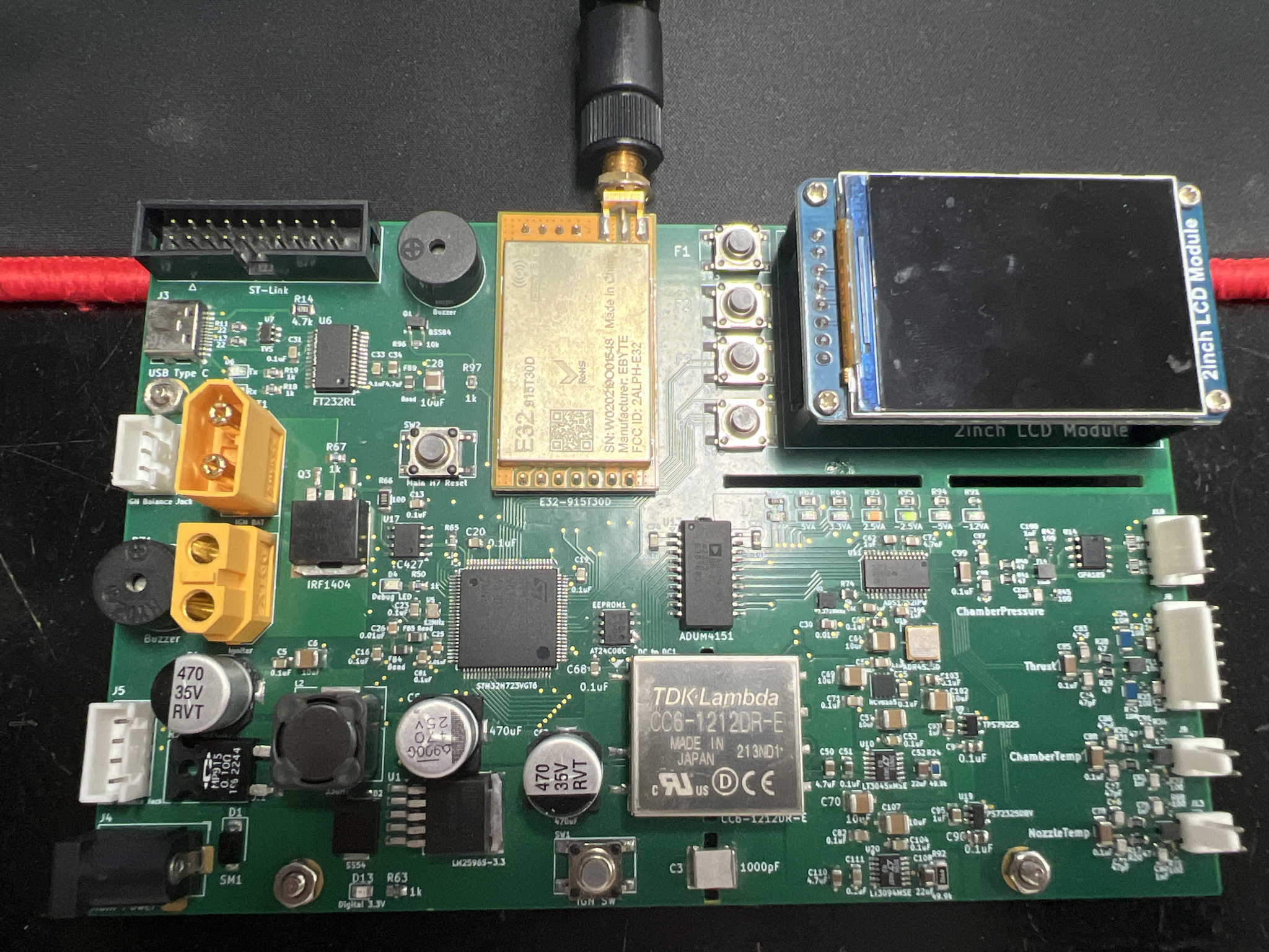
| 항목 | 부품 |
|---|---|
| MCU | STM32H723VGT6 (H7, 12 MHz TCXO) |
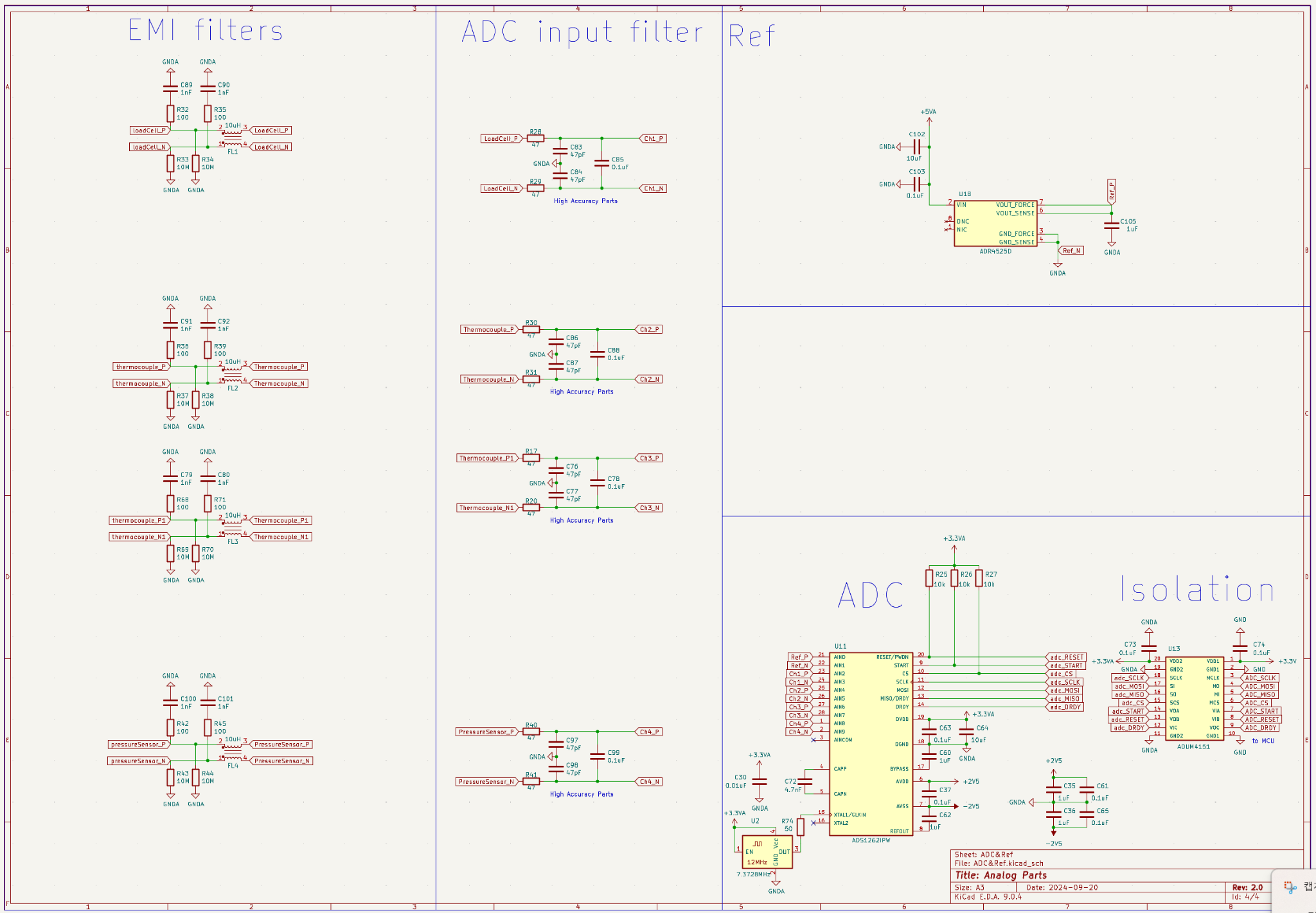
| 정밀 ADC | ADS1262IPW (ΔΣ, 24-bit) |
| SPI 절연 | ADuM4151 (MCU–ADC) |
| 기준전압 | ADR4525D |
| Op-Amp | OPA189, MCP6022, TLV9351 |
| 전류 센서 | INA219 (메인 배터리) |
| IMU | BNO085 (I²C) |
| 온도 센서 | AS6221 (MOSFET 온도) |
| EEPROM | AT24C08C (I²C) |
| 전원 | LM2596S-3.3, CC6-1212DR-E(±12 V) → LT3045(+5 V) / LT3094(−5 V) / TPS79225(+2.5 V) / TPS72325(−2.5 V) |
| 점화 경로 | TC427 게이트 드라이버 + IRF1404 파워 MOSFET, 물리 IGN SW |
| I/O | 2″ LCD, F1–F4 버튼, 부저, USB-UART(FT232RL), RF 모듈, ST-Link, 밸런스 잭 |
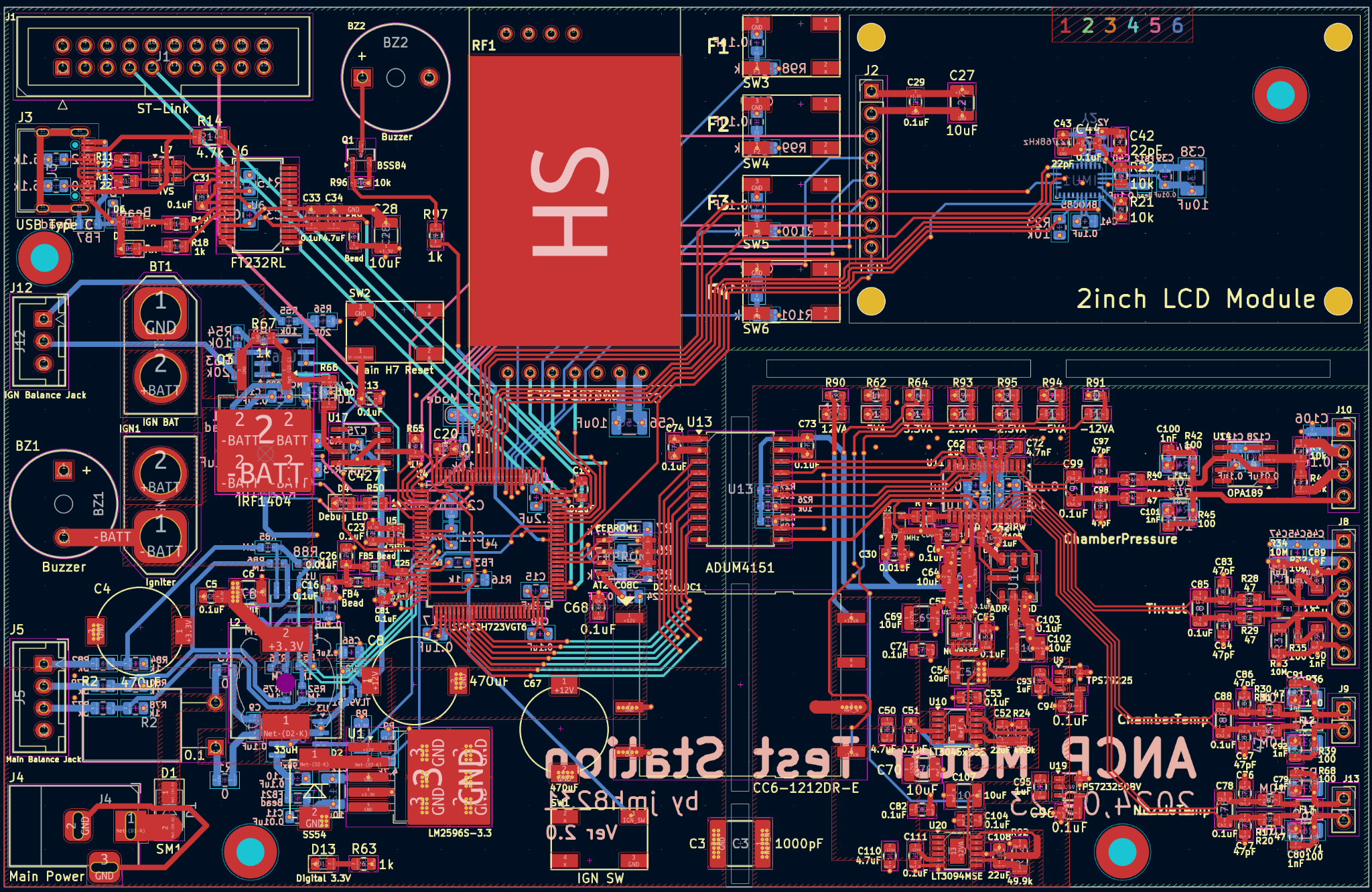
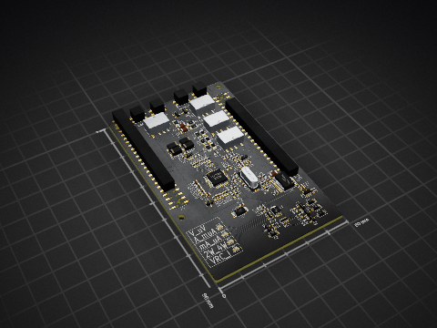
3D 렌더 (Top)
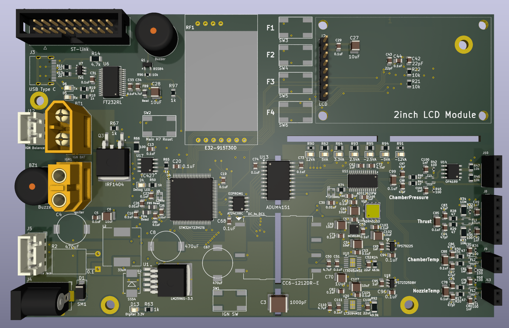
PCB 레이아웃(Top Routed)
fw/Drivers/lcd/LCD_2inch_st7789_v9_dma.c — ST7789 초기화 + DMA 라인 스트리머fw/Drivers/lcd/LVGL9_ST7789_Port_ULP.c — LVGL9 디스플레이 포트(플러시/세마포어)fw/Drivers/board/DEV_Config_h7.c — SPI4 DMA, D-Cache clean, TIM3 PWM 백라이트, OS-aware delaytask_gui, task_sense_fast, task_comms, task_control, task_logging// main.c
extern void lv_port_disp_init_st7789_v9_ulp(void);
void app_gui_init(void) {
lv_init();
lv_port_disp_init_st7789_v9_ulp(); // DMA flush, flush_wait 포함
// SquareLine 생성 코드 호출 ...
}D-Cache ON 환경에서는 DMA 전 송신 버퍼에 대해 SCB_CleanDCache_by_Addr() 처리 필수. 위 파일들에 구현 포함.
ADC Zero-Offset CAL: (ch, gain, sps) 조합별로 오프셋 저장. 부팅 시 전 페이지 스캔 → 이중 체크섬 검증 → RAM LUT 로드.
[32B Page Format]  (1 페이지 = 4개의 Offset)
0-1   : "EP" (헤더)
2     : CH/Gain 상위 3비트(6..3)
3     : SPS
4-7   : OFFSET[ch][gain][sps] (int32/Q-format)
8-13  : 다음 CH/Gain/SPS + OFFSET
14-15 : CHECKSUM #1 (0..13)

16-17 : "EP"
18-19 : CH/Gain/SPS
20-25 : OFFSET
26-29 : 다음 CH/Gain/SPS + OFFSET
30-31 : CHECKSUM #2 (16..29)if (mosfet_temp < T_th && thrust < F_th) hotwire_on();
else if (mosfet_temp > T_th && thrust < F_th) { hotwire_off(); show_overheat(); }
else hotwire_off(); // ignition success전송 패킷(예시): 0x48 0x53 | type | len | payload | CRC16
Main Power
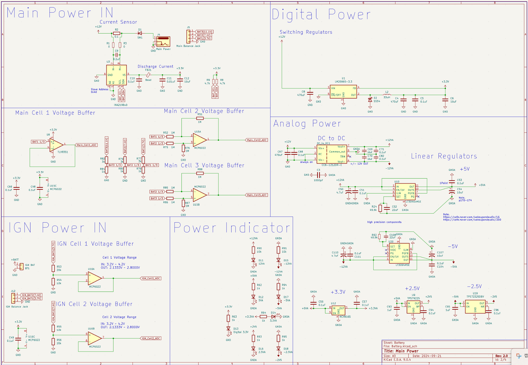
MCU
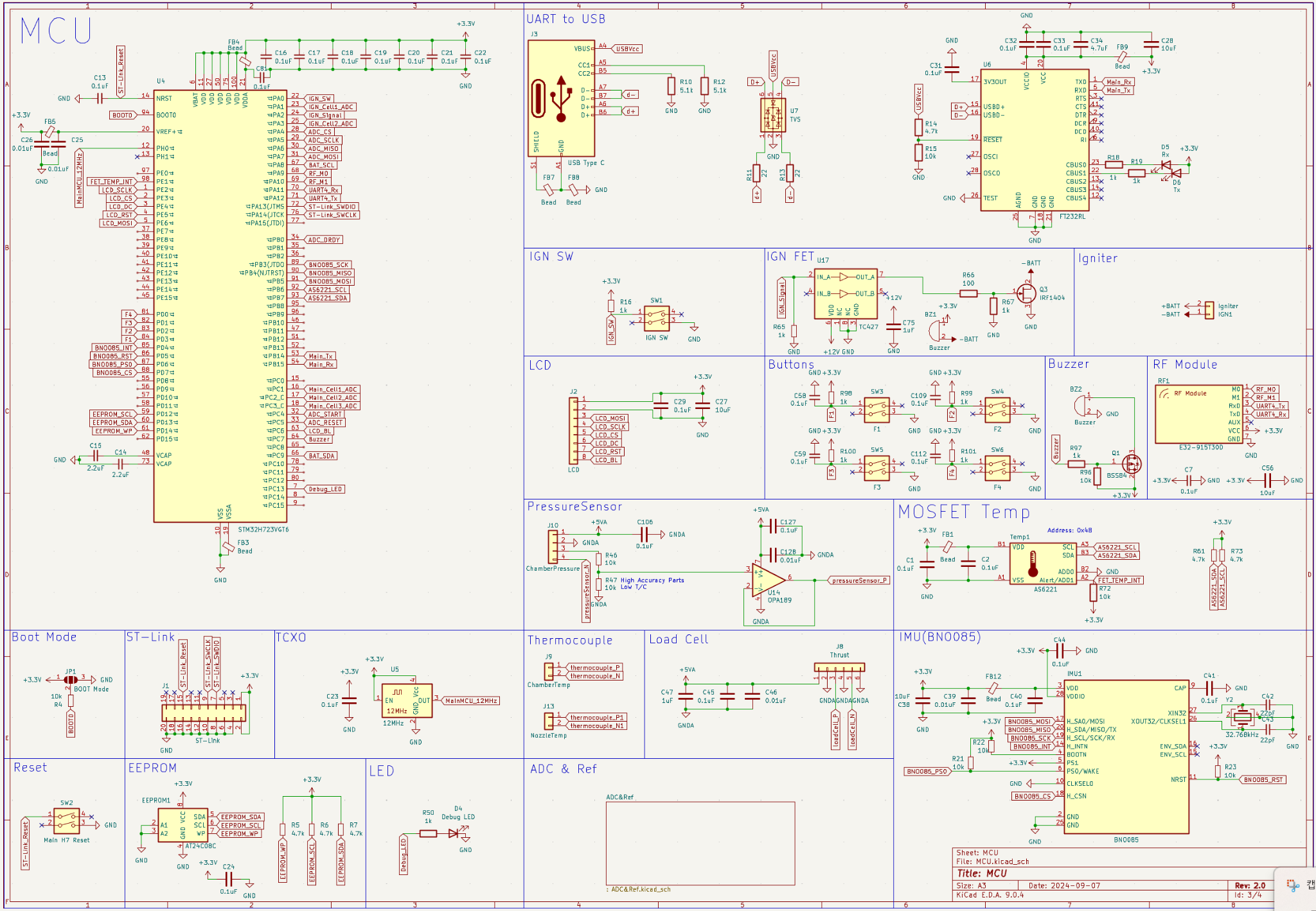
Analog/ADC/Isolation
lv_tick_inc()git clone https://github.com/jmh8231-Dev/ancp
# STM32CubeIDE에서 .ioc 열기 → 빌드 → ST-Link로 플래시ancp/
├─ fw/
│ ├─ Core/ # CubeMX 생성 코드
│ ├─ Drivers/
│ │ ├─ lvgl/ # LVGL v9
│ │ ├─ lcd/ # LCD_2inch_st7789_v9_dma.c, LVGL9_ST7789_Port_ULP.c
│ │ └─ board/ # DEV_Config_h7.c 등
│ ├─ app/ # tasks, ads1262, eeprom, telemetry, state machine
│ └─ middleware/ # FreeRTOS(선택)
├─ hw/ # 회로/PCB/거버
├─ docs/
│ └─ images/ # 사진/스크린샷
└─ README.md| Qty | Value | Footprint | References |
|---|---|---|---|
| 52 | 0.1uF | Capacitor_SMD:C_0805_2012Metric | C1, C2, C10, C13, C16, C17, C18, C19, C20, C103, C104, C106, C109, C111, C112, C127 +36 |
| 20 | 1k | Resistor_SMD:R_0805_2012Metric | R16, R18, R19, R50, R62, R63, R64, R65, R67, R78, R80, R84, R93, R94, R100, R101 +4 |
| 12 | 10uF | Capacitor_SMD:C_1210_3225Metric | C6, C12, C27, C28, C38, C54, C56, C64, C69, C70, C102, C107 |
| 10 | 10k | Resistor_SMD:R_0603_1608Metric | R4, R25, R26, R27, R54, R55, R72, R90, R91, R96 |
| 9 | 1uF | Capacitor_SMD:C_0805_2012Metric | C35, C36, C47, C60, C62, C75, C93, C95, C105 |
| 9 | Bead | Inductor_SMD:L_0805_2012Metric | FB1, FB3, FB4, FB5, FB7, FB8, FB9, FB12, FB21 |
| 8 | 100 | Resistor_SMD:R_0402_1005Metric | R32, R35, R36, R39, R42, R45, R68, R71 |
| 8 | 10M | Resistor_SMD:R_1206_3216Metric | R33, R34, R37, R38, R43, R44, R69, R70 |
| 8 | 1M | Resistor_SMD:R_0603_1608Metric | R51, R52, R75, R76, R85, R86, R87, R88 |
| 8 | 1nF | Capacitor_SMD:C_0805_2012Metric | C79, C80, C89, C90, C91, C92, C100, C101 |
| 8 | 4.7k | Resistor_SMD:R_1206_3216Metric | R5, R6, R7, R8, R9, R14, R61, R73 |
| 8 | 47 | Resistor_SMD:R_0805_2012Metric | R17, R20, R28, R29, R30, R31, R40, R41 |
| 8 | 47pF | Capacitor_SMD:C_0805_2012Metric | C76, C77, C83, C84, C86, C87, C97, C98 |
| 7 | 0.01uF | Capacitor_SMD:C_0805_2012Metric | C11, C25, C26, C30, C39, C46, C128 |
| 6 | 10k | Resistor_SMD:R_0805_2012Metric | R15, R21, R22, R23, R46, R47 |
| 4 | 0.1uF | Capacitor_SMD:C_1206_3216Metric | C78, C85, C88, C99 |
| 4 | 10uH | Inductor_SMD:L_CommonModeChoke_TDK_ACM2520-2P | FL1, FL2, FL3, FL4 |
| 3 | , , | ||
| 3 | 3k | Resistor_SMD:R_0805_2012Metric | R77, R79, R82 |
| 3 | 4.7uF | Capacitor_SMD:C_0805_2012Metric | C34, C50, C110 |
| 3 | 470uF | PCB:MVG25WV470M | C4, C8, C67 |
| 2 | 0 | Resistor_SMD:R_0805_2012Metric | R1, R3 |
| 2 | 2.2uF | Capacitor_SMD:C_0805_2012Metric | C14, C15 |
| 2 | 20k | Resistor_SMD:R_0805_2012Metric | R53, R56 |
| 2 | 22 | Resistor_SMD:R_0805_2012Metric | R11, R13 |
| 2 | 22pF | Capacitor_SMD:C_0805_2012Metric | C42, C43 |
| 2 | 22uF | Capacitor_SMD:C_0805_2012Metric | C52, C108 |
| 2 | 5.1k | Resistor_SMD:R_0805_2012Metric | R10, R12 |
| 2 | Buzzer | Buzzer_Beeper:Buzzer_12x9.5RM7.6 | BZ1, BZ2 |
| 2 | MCP6022 | Package_SO:SOIC-8_3.9x4.9mm_P1.27mm | U15, U16 |
| 1 | -12VA | LED_SMD:LED_0805_2012Metric | D15 |
| 1 | -2.5VA | LED_SMD:LED_0805_2012Metric | D18 |
| 1 | -5VA | LED_SMD:LED_0805_2012Metric | D17 |
| 1 | 0.1 | Package_TO_SOT_THT:TO-126-2_Horizontal_TabDown | R2 |
| 1 | 100 | Resistor_SMD:R_1206_3216Metric | R66 |
| 1 | 1000pF | Capacitor_SMD:C_2220_5750Metric | C3 |
| 1 | 12MHz | PCB:ECS-TXO-2016 | U5 |
| 1 | 12VA | LED_SMD:LED_0805_2012Metric | D11 |
| 1 | 2.5VA | LED_SMD:LED_0805_2012Metric | D16 |
| 1 | 3.3VA | LED_SMD:LED_0805_2012Metric | D14 |
| 1 | 32.768kHz | PCB:XC32M4 | Y2 |
| 1 | 33uH | Inductor_SMD:L_12x12mm_H8mm | L2 |
| 1 | 4.7nF | Capacitor_SMD:C_0805_2012Metric | C72 |
| 1 | 49.9k | Resistor_SMD:R_0805_2012Metric | R24 |
| 1 | 49.9k | Resistor_SMD:R_1206_3216Metric | R92 |
| 1 | 50 | Resistor_SMD:R_0805_2012Metric | R74 |
| 1 | 5VA | LED_SMD:LED_0805_2012Metric | D12 |
| 1 | 7.3728MHz | PCB:ASDMB-OSC | U2 |
| 1 | ADR4525D | Package_LCC:Analog_LCC-8_5x5mm_P1.27mm | U18 |
| 1 | ADS1262IPW | Package_SO:TSSOP-28_4.4x9.7mm_P0.65mm | U11 |
| 1 | ADUM4151 | Package_SO:SOIC-20W_7.5x12.8mm_P1.27mm | U13 |
| 1 | AS6221 | Package_CSP:WLCSP-6_1.4x1.0mm_P0.4mm | Temp1 |
| 1 | AT24C08C | Package_SO:SOIC-8_3.9x4.9mm_P1.27mm | EEPROM1 |
| 1 | BNO085 | Package_LGA:LGA-28_5.2x3.8mm_P0.5mm | IMU1 |
| 1 | BOOT Mode | Jumper:SolderJumper-3_P1.3mm_Open_RoundedPad1.0x1.5mm | JP1 |
| 1 | BSS84 | Package_TO_SOT_SMD:SOT-23 | Q1 |
| 1 | CC6-1212DR-E | PCB:CONV_CC6-1212SR-E | DC_to_DC1 |
| 1 | ChamberPressure | Connector_PinSocket_2.54mm:PinSocket_1x04_P2.54mm_Vertical | J10 |
| 1 | ChamberTemp | Connector_PinSocket_2.54mm:PinSocket_1x02_P2.54mm_Vertical | J9 |
| 1 | Debug LED | LED_SMD:LED_0805_2012Metric | D4 |
| 1 | Digital 3.3V | LED_SMD:LED_0805_2012Metric | D13 |
| 1 | E32-915T30D | PCB:E32-xxxTxxD | RF1 |
| 1 | F1 | PCB:SW_SMD_IT-1107 | SW3 |
| 1 | F2 | PCB:SW_SMD_IT-1107 | SW4 |
| 1 | F3 | PCB:SW_SMD_IT-1107 | SW5 |
| 1 | F4 | PCB:SW_SMD_IT-1107 | SW6 |
| 1 | FT232RL | Package_SO:SSOP-28_5.3x10.2mm_P0.65mm | U6 |
| 1 | IGN BAT | Connector_AMASS:AMASS_XT60-M_1x02_P7.20mm_Vertical | BT1 |
| 1 | IGN Balance Jack | Connector_JST:JST_XH_B3B-XH-A_1x03_P2.50mm_Vertical | J12 |
| 1 | IGN SW | PCB:SW_SMD_IT-1107 | SW1 |
| 1 | INA219BxD | Package_SO:SOIC-8_3.9x4.9mm_P1.27mm | U3 |
| 1 | IRF1404 | Package_TO_SOT_SMD:TO-263-2 | Q3 |
| 1 | Igniter | Connector_AMASS:AMASS_XT60-F_1x02_P7.20mm_Vertical | IGN1 |
| 1 | LCD | Connector_PinHeader_2.54mm:PinHeader_1x08_P2.54mm_Vertical | J2 |
| 1 | LM2596S-3.3 | Package_TO_SOT_SMD:TO-263-5_TabPin3 | U1 |
| 1 | LT3045xMSE | Package_SO:MSOP-12-1EP_3x4mm_P0.65mm_EP1.65x2.85mm | U10 |
| 1 | LT3094MSE | Package_SO:MSOP-12-1EP_3x4mm_P0.65mm_EP1.65x2.85mm | U20 |
| 1 | Main Balance Jack | Connector_JST:JST_XH_B4B-XH-A_1x04_P2.50mm_Vertical | J5 |
| 1 | Main H7 Reset | PCB:SW_SMD_IT-1107 | SW2 |
| 1 | Main Power | Connector_BarrelJack:BarrelJack_Horizontal | J4 |
The 269 most common of 286 parts.

charlesbaynham/DigitalTemperatureController
Schematic, PCB and source code for a high-precision digital temperature controller

camhan22/Motor-Controller
12-48VDC 65A Continuous 150A Peak brushed DC motor driver

sini6a/spotwelder
An easy-to-assemble, through-hole spot welder capable of switching high currents for welding nickel strip to lithium-ion cells. Controlled by an ATtiny13 microcontroller.


fgallud/tiva_c_connected
Is a very simple tcp modbus example for the tiva c connected board. It is written in C for the Energia IDE

It measures 155 × 100 mm and has 6 copper layers, 1.6 mm thick.
286 parts, built around the AS6221-EK, CC6-1212DR-E, MCP6022-I/P and ADS1262IPW. The full list of its parts is on this page, with links to each part's symbol and footprint where PCBKit's library has them.
From the jmh8231-Dev/ancp repository on GitHub, at the commit this page was made from: the board is Solid Rocket Motor Test Station - HW/ver 2.0/Solid Rocket Motor Test Station ver 2.0.kicad_pcb and its schematic Solid Rocket Motor Test Station - HW/ver 1.0/ADC&Ref.kicad_sch. PCBKit opens the board in the browser, with nothing to install.
Its repository states no licence, so its author keeps all rights: ask jmh8231-Dev before reusing the design.