2 layers99.1 × 62 mm
Nebulizer
OfficeChromatography/Nebulizer20x10
Stand-alone device for derivatizations and bioassays in planar chromatography
32 parts

 sini6a/spotwelder3
An easy-to-assemble, through-hole spot welder capable of switching high currents for welding nickel strip to lithium-ion cells. Controlled by an ATtiny13 microcontroller.
Dk spot welder is an open-source printed circuit board by sini6a, from the sini6a/spotwelder repository on GitHub. It is a 4-layer board of 112 × 72 mm with 51 parts on 25 nets, routed with 122 tracks and 458 vias.
It is built around the ATTINY13-20PU, MCP1407-E/P and L7805, with the IRF1404 and 5.0SMDJ14A among its other parts. Its parts include 16 resistors, 8 capacitors, 8 transistors, 6 diodes and 4 ICs. It belongs with the AVR (ATmega, ATtiny) boards of this library.


An easy-to-assemble, through-hole spot welder capable of switching high currents for welding nickel strip to lithium-ion cells. Controlled by an ATtiny13 microcontroller.
The welder is powered by a 12 V car battery or another suitable high-current battery source. The PCB, schematic, firmware, enclosure, and fabrication files are included in this repository.
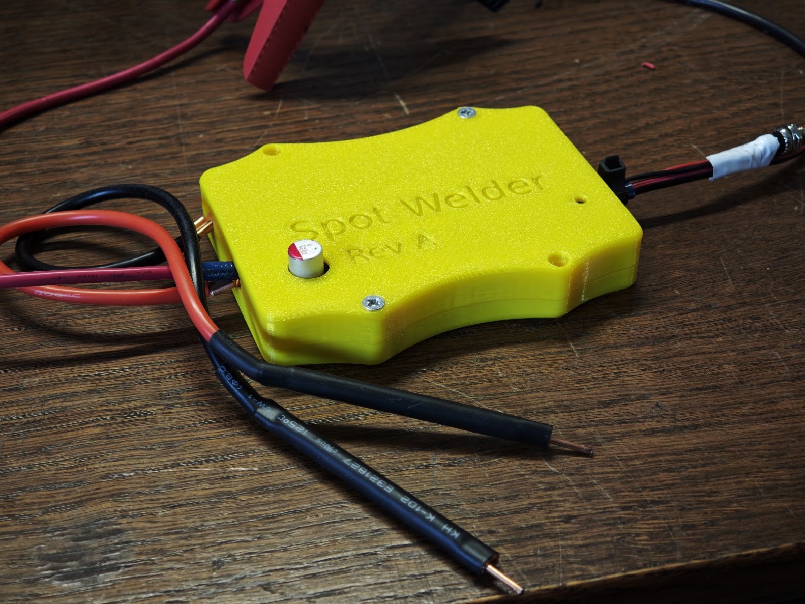
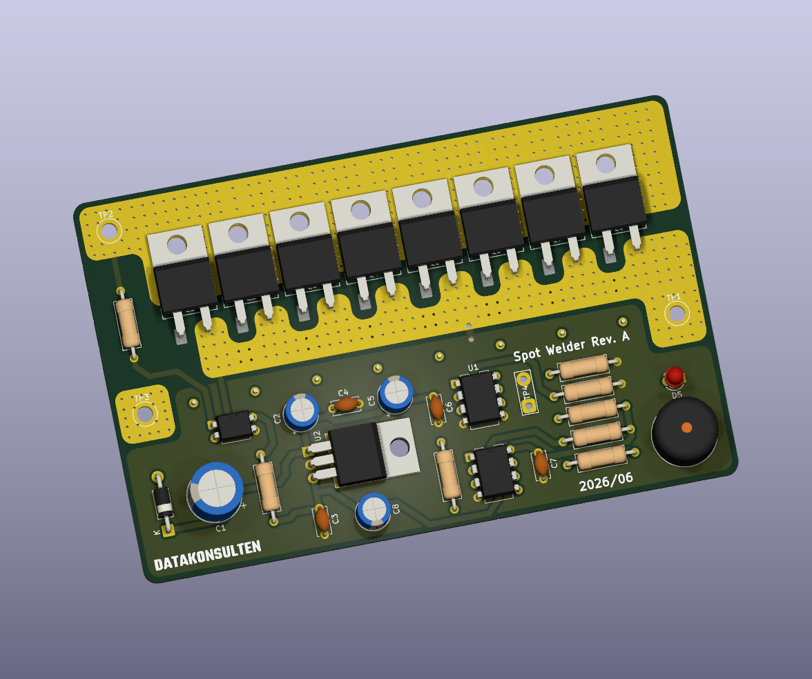
[!WARNING] This project switches extremely high current from a battery. Incorrect wiring, insufficient conductors, short circuits, or excessive pulse duration can cause fire, burns, damaged cells, destroyed MOSFETs, or battery failure.
PCB fabrication for this project was sponsored by PCBWay.
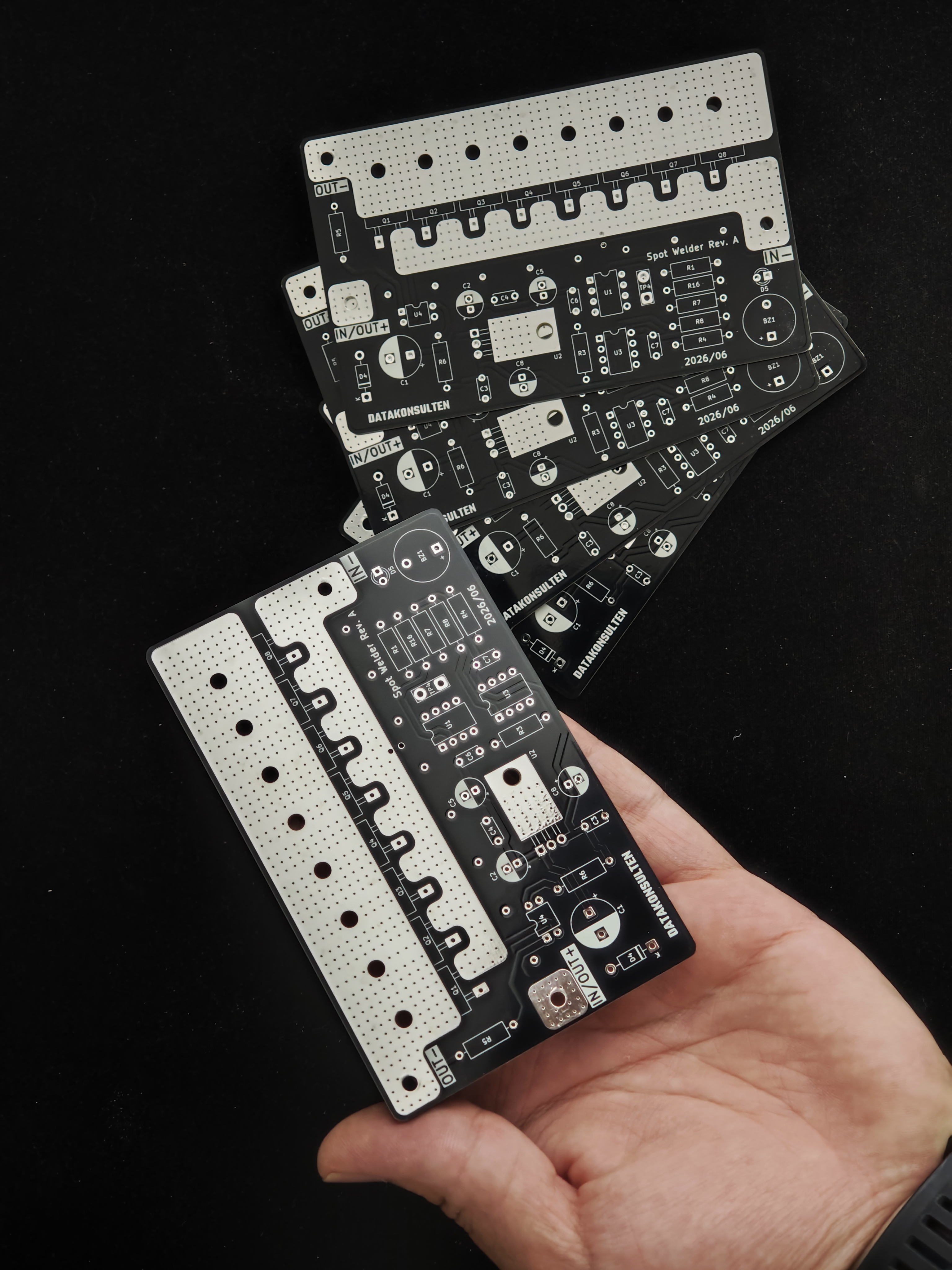
Eight-MOSFET switching bank Eight IRF1404 N-channel MOSFETs are connected in parallel to switch the welding current. Each MOSFET has an individual 10 Ω gate resistor to help control switching and reduce gate ringing.
Dedicated MOSFET gate driver An MCP1407 drives all eight MOSFET gates simultaneously. A hardware pull-down resistor on the driver input keeps the MOSFET bank off while the microcontroller is starting, resetting, or unpowered.
Automatic touch-to-weld triggering A PC817 optocoupler-based sensing circuit detects when both welding probes are in contact with a conductive workpiece. The isolated output signals the ATtiny13 to begin the welding sequence.
Adjustable 1–10 ms main pulse A pushbutton connected to TP4 cycles the main weld-pulse duration from 1 to 10 ms.
EEPROM setting storage The selected weld duration is saved in the ATtiny13 EEPROM and restored after the welder is disconnected from power.
LED and buzzer feedback The onboard LED and passive piezo buzzer provide startup, welding, and setting-change feedback. When the duration is changed, the LED flashes and the buzzer beeps once for each selected millisecond.
Optional double-pulse welding The firmware can produce a short pre-pulse followed by the adjustable main pulse. The pre-pulse can help settle the probe contact before the main weld.
Separated control and power grounds
The high-current welding ground (GND) and logic ground (CTRL_GND) are routed separately and joined at a single net-tie point to reduce switching noise at the microcontroller.
Reverse-polarity protection A 1N5819 Schottky diode protects the 5 V control supply if the battery input is accidentally connected with reversed polarity.
Transient suppression Four 5.0SMDJ14A TVS diodes help clamp voltage transients generated by the welding cables and other parasitic inductance when the MOSFET bank switches off.
Large high-current connection pads The battery and welding connections use large exposed copper pads intended for soldered or mechanically secured high-current conductors.
Four-layer PCB Copper zones on F.Cu, In1.Cu, In2.Cu, and B.Cu help distribute the short welding-current pulses through the MOSFET bank.
[!IMPORTANT] PCB copper alone should not be treated as a complete high-current busbar. Thick copper cable, copper braid, copper strip, or another suitable reinforcement is recommended for the main battery and electrode current paths.
Power input
A 12 V car battery or another suitable high-current battery source is connected to the IN/OUT+ and IN- pads.
Probe contact detection When both welding probes contact the conductive workpiece, the PC817 sensing circuit produces an isolated trigger signal for the ATtiny13.
Trigger validation The firmware verifies that the contact signal remains active for the configured debounce period.
Pre-pulse When double-pulse mode is enabled, the ATtiny13 briefly activates the MCP1407 and MOSFET bank for the configured pre-pulse duration.
Pulse gap The MOSFETs switch off for a short interval before the main pulse.
Main weld pulse The MOSFET bank switches on for the selected duration between 1 and 10 ms, passing a short burst of high current through the nickel strip and cell connection.
Feedback and cooldown The buzzer and LED confirm that the weld sequence completed. The firmware then enforces a cooldown period and waits for the probes to be lifted before another weld can begin.
TP4 is used to change the main weld-pulse duration.
Each complete button press advances the setting by 1 ms:
1 → 2 → 3 → 4 → 5 → 6 → 7 → 8 → 9 → 10 → 1 msAfter the value changes:
For example, a 6 ms setting produces six LED flashes and six beeps.
The displayed value represents the main pulse only. When double-pulse mode is enabled, the fixed pre-pulse is added separately.
The firmware is located at:
Firmware/main.cIt directly controls:
The firmware forces the MOSFET-driver control pin low during startup. This works together with the hardware pull-down resistor on the MCP1407 input to reduce the risk of an unintended weld pulse during reset or power-up.
| Definition | Default | Description |
|---|---|---|
WELD_PULSE_MIN_MS | 1 ms | Lowest selectable main-pulse duration |
WELD_PULSE_MAX_MS | 10 ms | Highest selectable main-pulse duration |
WELD_PULSE_DEFAULT_MS | 6 ms | Used when EEPROM does not contain a valid setting |
USE_DOUBLE_PULSE | 1 | Enables the pre-pulse and main-pulse sequence |
PRE_PULSE_MS | 3 ms | Fixed pre-pulse duration |
PULSE_GAP_MS | 80 ms | Delay between the pre-pulse and main pulse |
WELD_COOLDOWN_MS | 800 ms | Minimum delay after a weld before re-arming |
TRIGGER_DEBOUNCE_MS | 15 ms | Probe-contact validation time |
REQUIRE_TRIGGER_RELEASE | 1 | Requires the probes to be lifted before another weld |
BEEP_ON_WELD_MS | 60 ms | Weld-confirmation tone duration |
BUZZER_ACTIVE_TYPE | 0 | Configures BZ1 as an externally driven passive piezo |
BUZZER_TONE_HZ | 4000 Hz | Normal feedback-tone frequency |
Review the values in Firmware/main.c before flashing, as development versions may use different pre-pulse and timing defaults.
The firmware is built with AVR-GCC and optimized for the ATtiny13's limited 1 KB program memory.
cd Firmware

make
make flash
make fuses
The default Makefile targets are:
| Command | Action |
|---|---|
make | Build the firmware and generate the HEX file |
make flash | Flash the firmware over ISP |
make fuses | Configure the 9.6 MHz internal oscillator with the divide-by-8 fuse, resulting in a 1.2 MHz CPU clock |
The default programmer configuration may need to be changed in the Makefile when using an Arduino as ISP instead of a USBasp.
A two-piece enclosure is included and was designed in FreeCAD. 3xM4 Nuts should be installed while printing the enclosure.
| Assembled | Top and bottom |
|---|---|
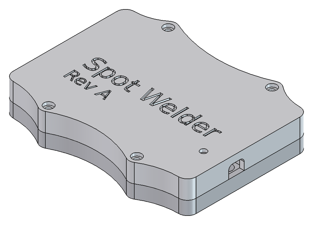 | 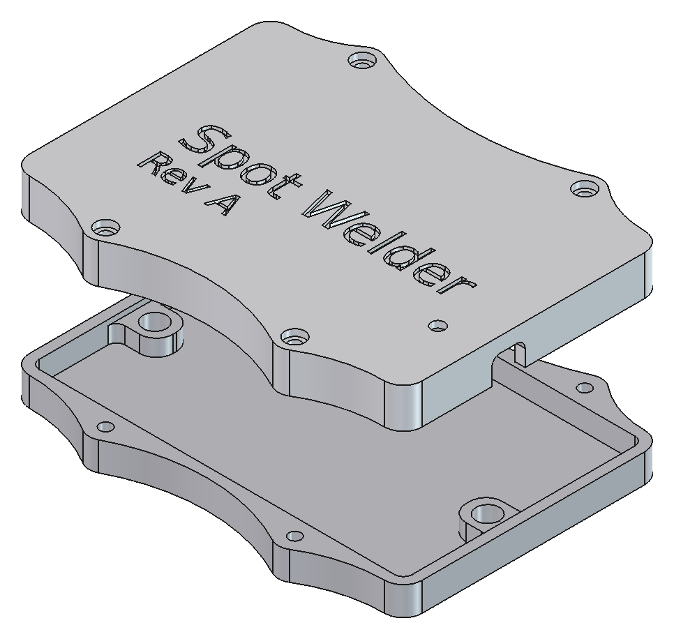 |
The enclosure includes:
Included files:
Enclosure/SpotWelder.FCStd
Enclosure/Top Body.step
Enclosure/Bottom Body.stepThe Rev A hardware has been assembled, powered, and successfully used for spot welding.
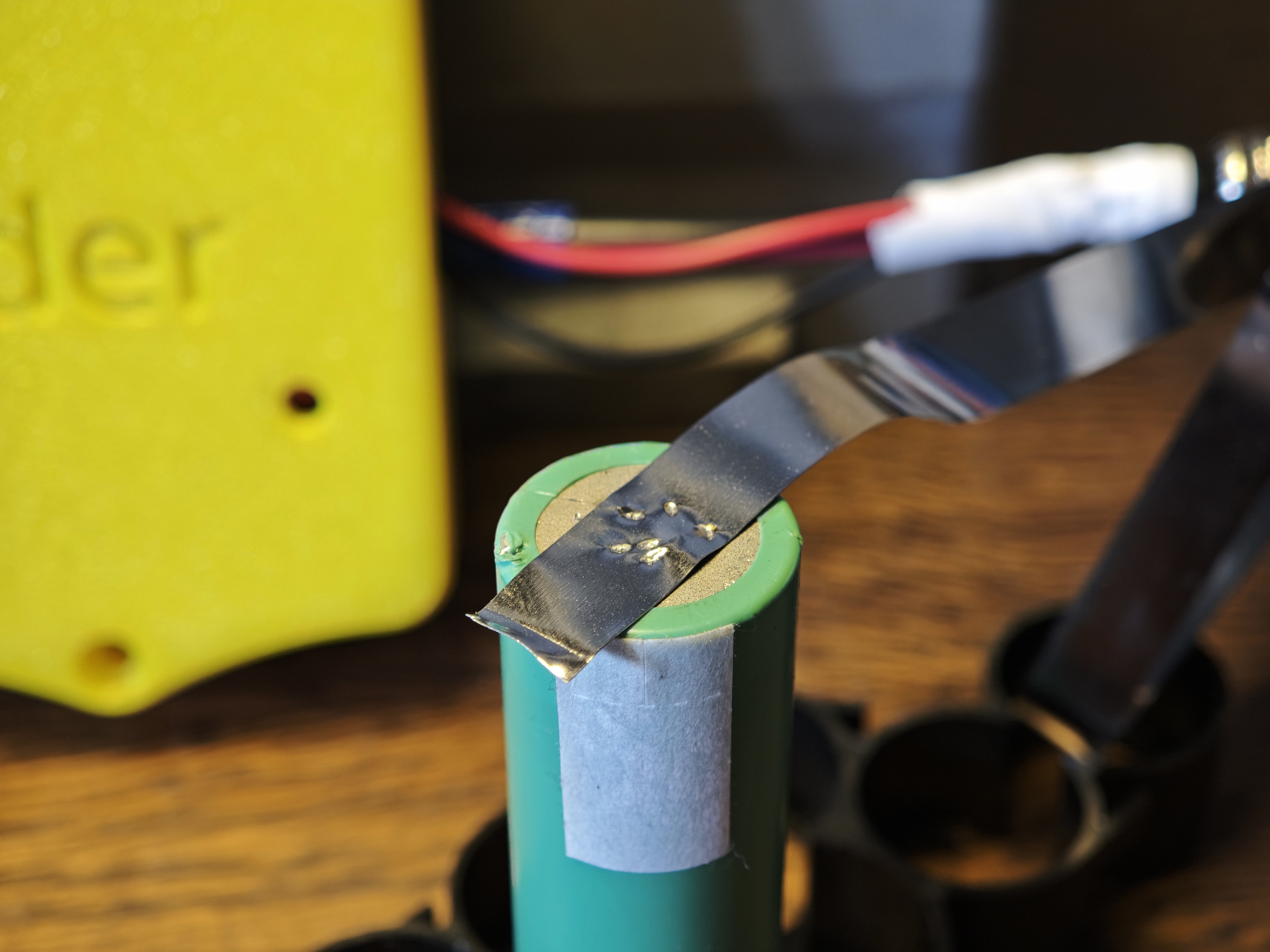
The following core functions have been tested:
This project is licensed under the Creative Commons Attribution-NonCommercial-ShareAlike 4.0 International license.
See LICENCE.md for the complete terms.
You may build, modify, and share the design for personal and non-commercial use, provided that attribution is retained and derivative works use the same license.
Commercial production or resale of boards based on this design requires permission from Datakonsulten Sverige AB.
| Qty | Value | Footprint | References |
|---|---|---|---|
| 8 | 10R | Resistor_THT:R_Axial_DIN0309_L9.0mm_D3.2mm_P12.70mm_Horizontal | R2, R9, R10, R11, R12, R13, R14, R15 |
| 8 | IRF1404 | SpotWelderFootprints:TO-220-2_Horizontal_TabDown | Q1, Q2, Q3, Q4, Q5, Q6, Q7, Q8 |
| 4 | 100n | Capacitor_THT:C_Disc_D5.0mm_W2.5mm_P5.00mm | C3, C4, C6, C7 |
| 4 | 10k | Resistor_THT:R_Axial_DIN0309_L9.0mm_D3.2mm_P12.70mm_Horizontal | R6, R7, R8, R16 |
| 4 | 5.0SMDJ14A | SpotWelderFootprints:D_SMC_Handsoldering | D1, D2, D3, D6 |
| 3 | 10u | Capacitor_THT:CP_Radial_D6.3mm_P2.50mm | C2, C5, C8 |
| 2 | 2k | Resistor_THT:R_Axial_DIN0309_L9.0mm_D3.2mm_P12.70mm_Horizontal | R1, R5 |
| 2 | 470R | Resistor_THT:R_Axial_DIN0309_L9.0mm_D3.2mm_P12.70mm_Horizontal | R3, R4 |
| 2 | LOGO | LOGO | G***, G*** |
| 1 | 1N5819 | Diode_THT:D_DO-41_SOD81_P10.16mm_Horizontal | D4 |
| 1 | 470u | Capacitor_THT:CP_Radial_D10.0mm_P5.00mm | C1 |
| 1 | ATtiny13-20P | Package_DIP:DIP-8_W7.62mm | U3 |
| 1 | Buzzer | Buzzer_Beeper:Buzzer_12x9.5RM7.6 | BZ1 |
| 1 | IN- | MountingHole:MountingHole_4mm_Pad_Via | TP1 |
| 1 | IN/OUT+ | MountingHole:MountingHole_4mm_Pad_Via | TP3 |
| 1 | L7805 | Package_TO_SOT_THT:TO-220-3_Horizontal_TabDown | U2 |
| 1 | LED_Small | LED_THT:LED_D3.0mm | D5 |
| 1 | MCP1407 | Package_DIP:DIP-8_W7.62mm | U1 |
| 1 | NetTie_2 | NetTie:NetTie-2_THT_Pad1.0mm | NT1 |
| 1 | OUT- | MountingHole:MountingHole_4mm_Pad_Via | TP2 |
| 1 | PC817 | Package_DIP:DIP-4_W7.62mm | U4 |
| 1 | WELD_BTN | TestPoint:TestPoint_2Pads_Pitch5.08mm_Drill1.3mm | TP5 |
| 1 | WELD_DURATION | TestPoint:TestPoint_2Pads_Pitch5.08mm_Drill1.3mm | TP4 |
OfficeChromatography/Nebulizer20x10
Stand-alone device for derivatizations and bioassays in planar chromatography

camhan22/Motor-Controller
12-48VDC 65A Continuous 150A Peak brushed DC motor driver


KaeptnBalu/Arduino_Spot_Welder_V3
This is the Kicad project for V3.1 The Arduino Board was not changed, only the Mosfet Board got a updgrade.

KaeptnBalu/Arduino_Spot_Welder_V4
This is V4 of the Arduino Spot Welder. An Arduino based Spot Welder for battery welding

KaeptnBalu/Arduino_Spot_Welder_V2
Arduino controlled Spot Welder for battery welding

nekonaute/pogobot
Pogobot is an open-source open-hardware robotic platform for swarm robotics
It measures 112 × 72 mm and has 4 copper layers, 1.6 mm thick.
51 parts, built around the ATTINY13-20PU, MCP1407-E/P, L7805 and IRF1404. The full list of its parts is on this page, with links to each part's symbol and footprint where PCBKit's library has them.
From the sini6a/spotwelder repository on GitHub, at the commit this page was made from: the board is KiCad/dk-spot-welder.kicad_pcb and its schematic KiCad/dk-spot-welder.kicad_sch. PCBKit opens the board in the browser, with nothing to install.
Its repository states no licence, so its author keeps all rights: ask sini6a before reusing the design.