2 layers100 × 100 mm
Heatplate v1.1
DerSpatz/PCB-reflow-solder-heat-plate
hardware design for a PCB reflow solder heat plate
57 parts179MIT
 Jgriffiths92/OpenRGB_Pico_Controller
This project is an open-source RGB controller designed to interface with 12v RGB devices using a Raspberry Pi Pico microcontroller.
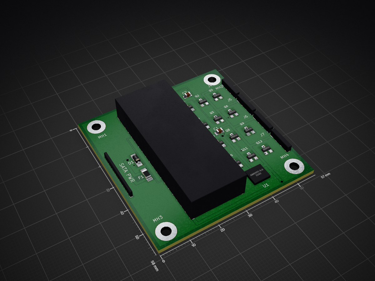
RGB PICO SATA CONTROLLER is an open-source printed circuit board by Jgriffiths92, from the Jgriffiths92/OpenRGB_Pico_Controller repository on GitHub. It is a 4-layer board of 57 × 58 mm with 27 parts on 28 nets, routed with 190 tracks and 48 vias.
It is built around the AMS1117-5.0 and 1.5KE12A. Its parts include 12 transistors, 6 connectors, 2 capacitors, 1 IC and 1 diode. It belongs with the lEDs and displays boards and the RP2040 boards of this library.


This project is an open-source RGB controller designed to interface with 12v RGB devices using a Raspberry Pi Pico microcontroller. It features custom firmware and hardware, supporting the OpenRGB protocol for seamless integration with popular RGB control software.
RGB Pico SATA Controller is an open-source hardware and firmware project that enables control of standard (dumb) 12V RGB devices (such as common 12V RGB LED strips and PC lighting) using a Raspberry Pi Pico microcontroller. The controller connects via a SATA power connector for easy integration into PC builds and communicates with the OpenRGB desktop application using the OpenRGB protocol. This allows users to synchronize and customize their RGB lighting through a unified software interface.
The project includes:
Firmware/ — Source code for the Pico firmware (C, CMake)Gerber/ — PCB manufacturing files for the controllerRGB_PICO_SATA_CONTROLLER.kicad_* — KiCad schematic and PCB design filesThe hardware consists of a custom PCB designed in KiCad, featuring:
All design files are provided in the repository (.kicad_sch, .kicad_pcb, and Gerber files).
RGB_PICO_SATA_CONTROLLER.kicad_sch, .kicad_pcb) to view or modify the schematic and PCB layout.Gerber/ directory to order PCBs from your preferred manufacturer.Firmware/ directory.mkdir build
cd build
cmake ..
make.uf2 file to the Pico's USB drive.The firmware implements the OpenRGB protocol, allowing the controller to be recognized and managed by the OpenRGB desktop application. For protocol details, see Firmware/openrgb_protocol.c and Firmware/openrgb_protocol.h.
Contributions are welcome! Please open issues or pull requests for bug fixes, new features, or suggestions.
This project is licensed under the GNU General Public License v3.0 (GPLv3).
Copyright (C) [2026] [Your Name or Organization]
This program is free software: you can redistribute it and/or modify it under the terms of the GNU General Public License as published by the Free Software Foundation, either version 3 of the License, or (at your option) any later version.
This program is distributed in the hope that it will be useful, but WITHOUT ANY WARRANTY; without even the implied warranty of MERCHANTABILITY or FITNESS FOR A PARTICULAR PURPOSE. See the GNU General Public License for more details.
You should have received a copy of the GNU General Public License along with this program. If not, see https://www.gnu.org/licenses/.
Feel free to contribute or open issues for suggestions and improvements.
| Qty | Value | Footprint | References |
|---|---|---|---|
| 12 | NMOS | Package_TO_SOT_SMD:SOT-23 | Q1, Q2, Q3, Q4, Q5, Q6, Q7, Q8, Q9, Q10, Q11, Q12 |
| 4 | MountingHole:MountingHole_3.2mm_M3 | MH1, MH2, MH3, MH4 | |
| 2 | 10uF | Capacitor_SMD:C_0805_2012Metric | C1, C2 |
| 1 | 1.5KE12A | Diode_SMD:D_SMB | D1 |
| 1 | 1A | Fuse:Fuse_1206_3216Metric | F1 |
| 1 | AMS1117-5.0 | Package_TO_SOT_SMD:SOT-223-3_TabPin2 | U1 |
| 1 | PICO_HEADER | Connector_PinHeader_2.54mm:PinHeader_2x20_P2.54mm_Vertical | J2 |
| 1 | RGB1 | Connector_PinHeader_2.54mm:PinHeader_1x04_P2.54mm_Vertical | J4 |
| 1 | RGB2 | Connector_PinHeader_2.54mm:PinHeader_1x04_P2.54mm_Vertical | J5 |
| 1 | RGB3 | Connector_PinHeader_2.54mm:PinHeader_1x04_P2.54mm_Vertical | J6 |
| 1 | RGB4 | Connector_PinHeader_2.54mm:PinHeader_1x04_P2.54mm_Vertical | J7 |
| 1 | SATA_POWER | Connector_PinHeader_2.54mm:PinHeader_1x15_P2.54mm_Vertical | J1 |
DerSpatz/PCB-reflow-solder-heat-plate
hardware design for a PCB reflow solder heat plate

rheslip/2HPico-Eurorack-Module-Hardware
2HP Eurorack module based on Raspberry Pi Pico 2

victorhook/asac-fc
asac fc is an rp2040 based flight controller made for FPV drone flying


johannesstrueber/dots
DOTS eurorack module pcb schematics and code ATMega328 based


It measures 57 × 58 mm and has 4 copper layers, 1.6 mm thick.
27 parts, built around the AMS1117-5.0 and 1.5KE12A. The full list of its parts is on this page, with links to each part's symbol and footprint where PCBKit's library has them.
From the Jgriffiths92/OpenRGB_Pico_Controller repository on GitHub, at the commit this page was made from: the board is RGB_PICO_SATA_CONTROLLER.kicad_pcb and its schematic RGB_PICO_SATA_CONTROLLER.kicad_sch. PCBKit opens the board in the browser, with nothing to install.
Its repository states no licence, so its author keeps all rights: ask Jgriffiths92 before reusing the design.