Skip to the content
PCBKitNew board
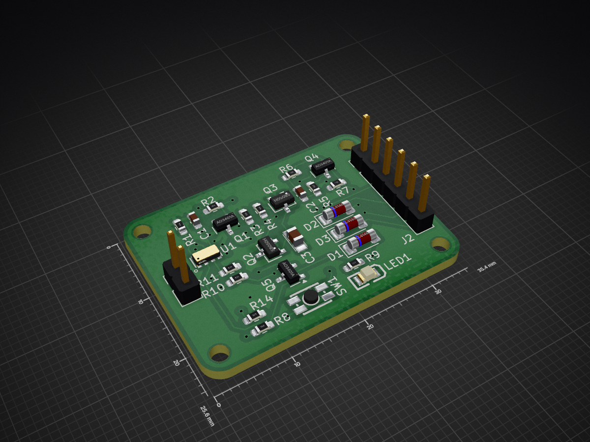
2 layers35.4 × 25.6 mmPowerTimer, the printed circuit board in 3D

Module to jump from miliAmperes to nanoAmperes on Idle mode.

Size
35.4 × 25.6 mm
Copper layers
2
Thickness
1.6 mm
Parts
33
Nets
19
Pads
77
Tracks, vias
173, 33
Pours
3
Routed
Yes
KiCad
KiCad 8.0 (file 20240108)
Created
28 Jun 2025
Updated
11 Apr 2026

Overview

PowerTimer is an open-source printed circuit board by jfm92, from the jfm92/powerTimer repository on GitHub. It is a 2-layer board of 35.4 × 25.6 mm with 33 parts on 19 nets, routed with 173 tracks and 33 vias.

It is built around the AO3401A, LL4148 and S8050H, with the TAJA475K016RNJ and TS-1185EC-C-D-B among its other parts. Its parts include 12 resistors, 5 transistors, 4 diodes, 3 capacitors and 2 connectors.

Main components

5

README

README.md

Power Timer

Project Description

The Power Timer is an ultra-low power module that allows you to control the output power by software. It is mainly based on a Real-Time Clock (RTC) and an RS circuit. Thanks to the RTC, you can control the exact wake-up date or the periodicity. It also allows for external interruptions, which gives you the benefits of ultra-low power consumption while being able to connect other types of sensors. The module is based on the RV3028-C7 chip. It is also compatible with Arduino, thanks to its custom library.

The sleep current of the module is around 50nA at 3.3V, making it ideal for battery-powered applications.
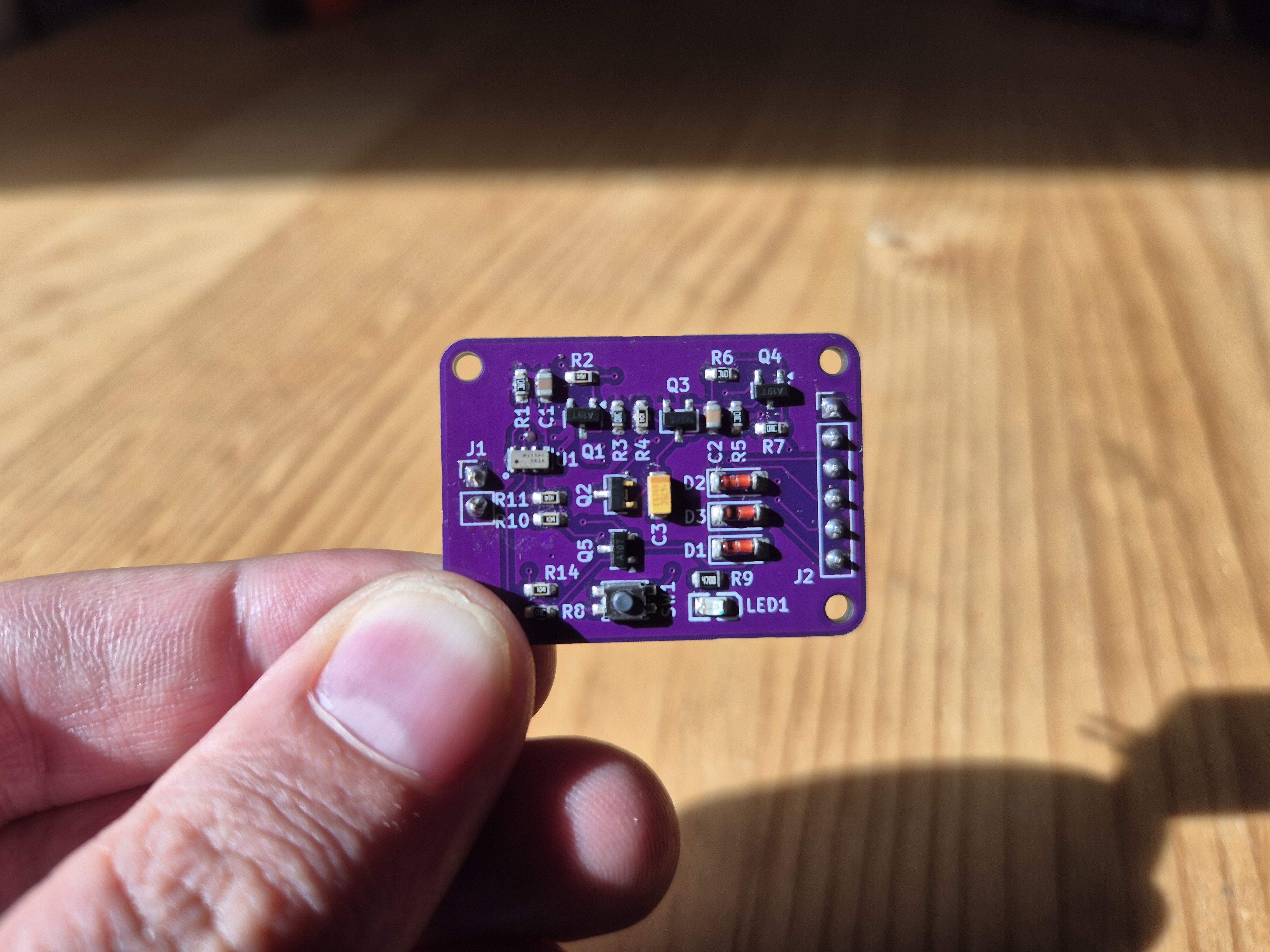
Consumption comparison:

Demo with software sleep modes:
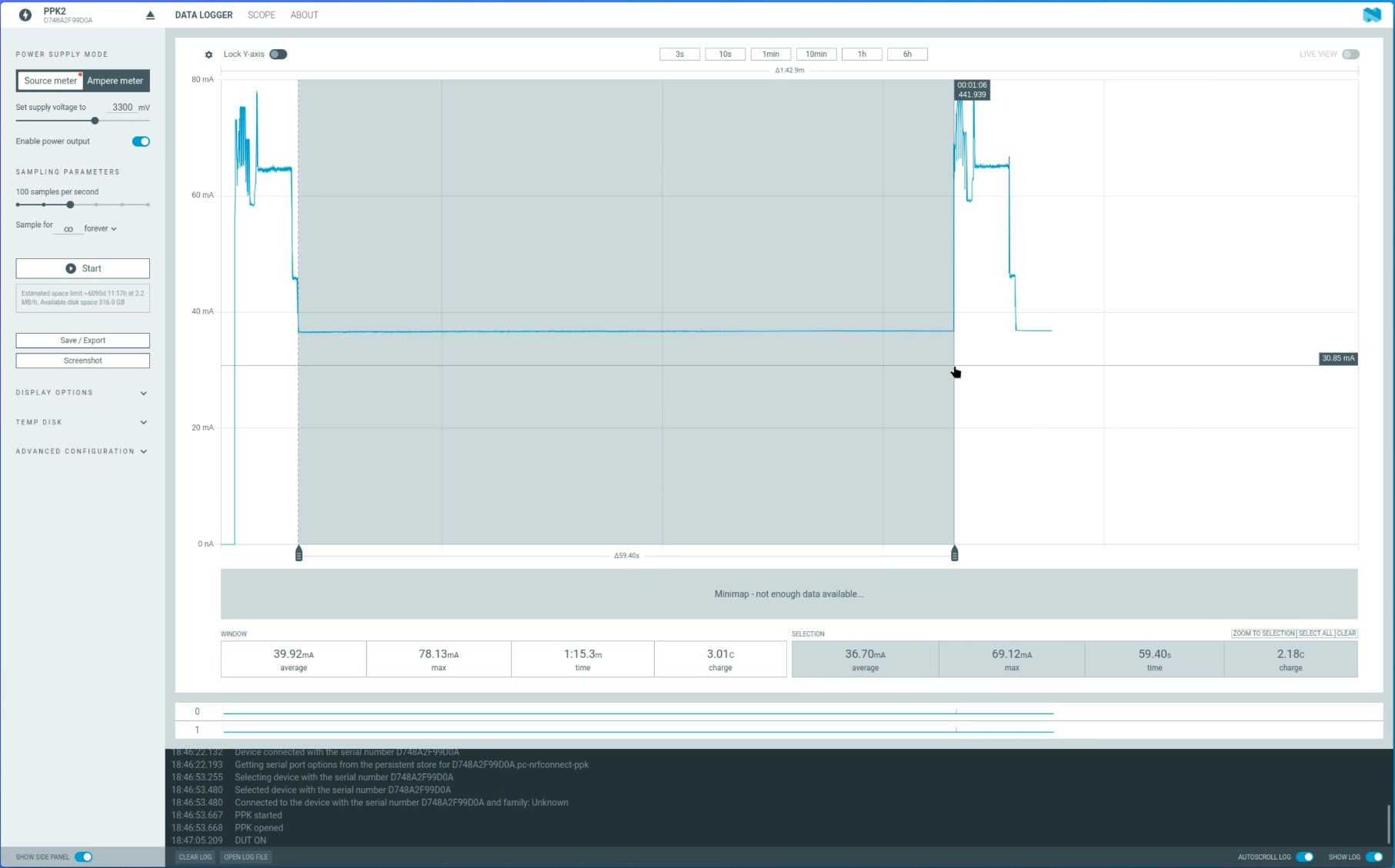
Same demo with powerTimer:
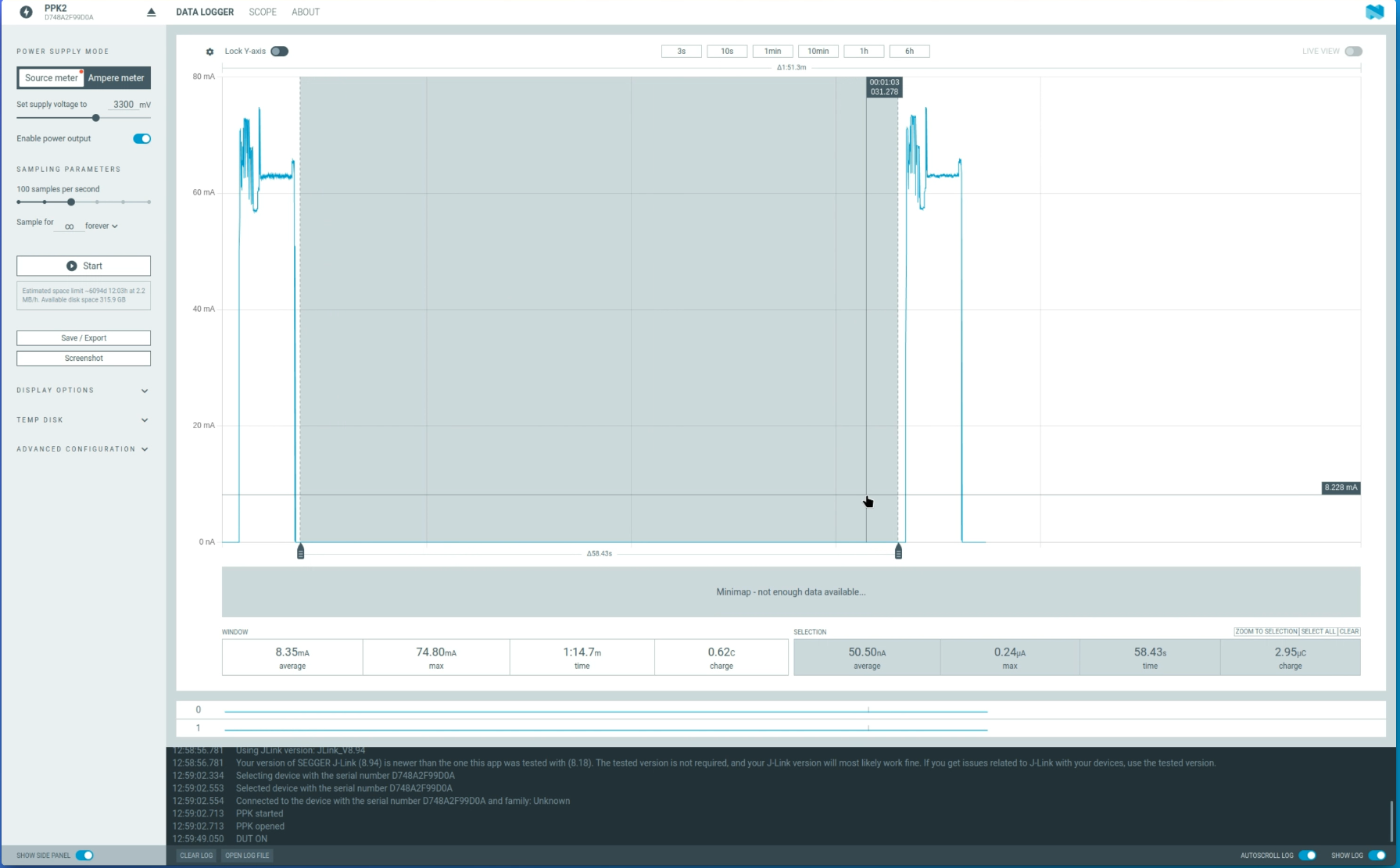
734.000 times less idle consumption!

How it works

The module is designed to be a versatile power control unit for your projects. It can be used as a simple timer to power on a device at a specific time or periodically, or it can be used as a power management unit that can be woken up by external events.
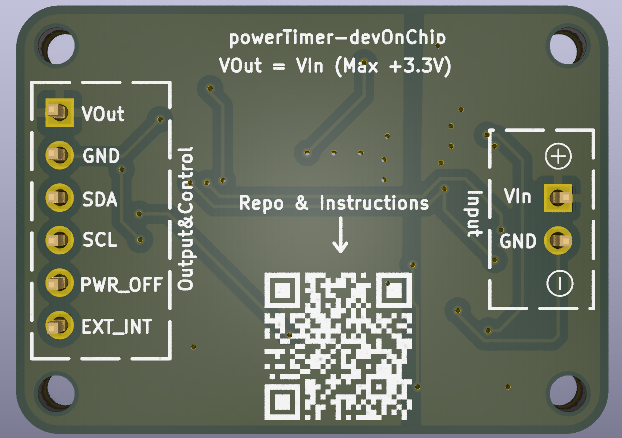
Power Timer Diagram

The PCB is divided into two parts:

  • Input: The input voltage (VINput) can be from 1.1V to 5.5V. This wide input range makes it compatible with a variety of power sources, from a single-cell Li-Po battery to a 5V power supply.

  • Output:

    • I2C: The I2C pins (SDA and SCL) are used to program the RV3028-C7 RTC. You can set the time, date, and alarms using any microcontroller with I2C capabilities.
    • VOutput: This pin will provide the same voltage as the input. When the module is in the "ON" state, the VOutput pin is connected to the VINput pin, providing power to your external device.
    • PWR_OFF: This input allows you to externally cut off the power of the module. By pulling this pin high, you can force the module into the "OFF" state, even if the RTC alarm is active.
    • EXT_INT: This input allows you to wake up the module externally using another sensor. This is useful for applications where you want to wake up the main device based on an external event, such as a button press or a sensor reading.
    • On-board button: A push button is available on the board for manual wake-up. This allows you to turn on the module without relying on the RTC alarm or an external interrupt.

The logic levels of the I2C bus and the external interrupt input depend on the selected input voltage.

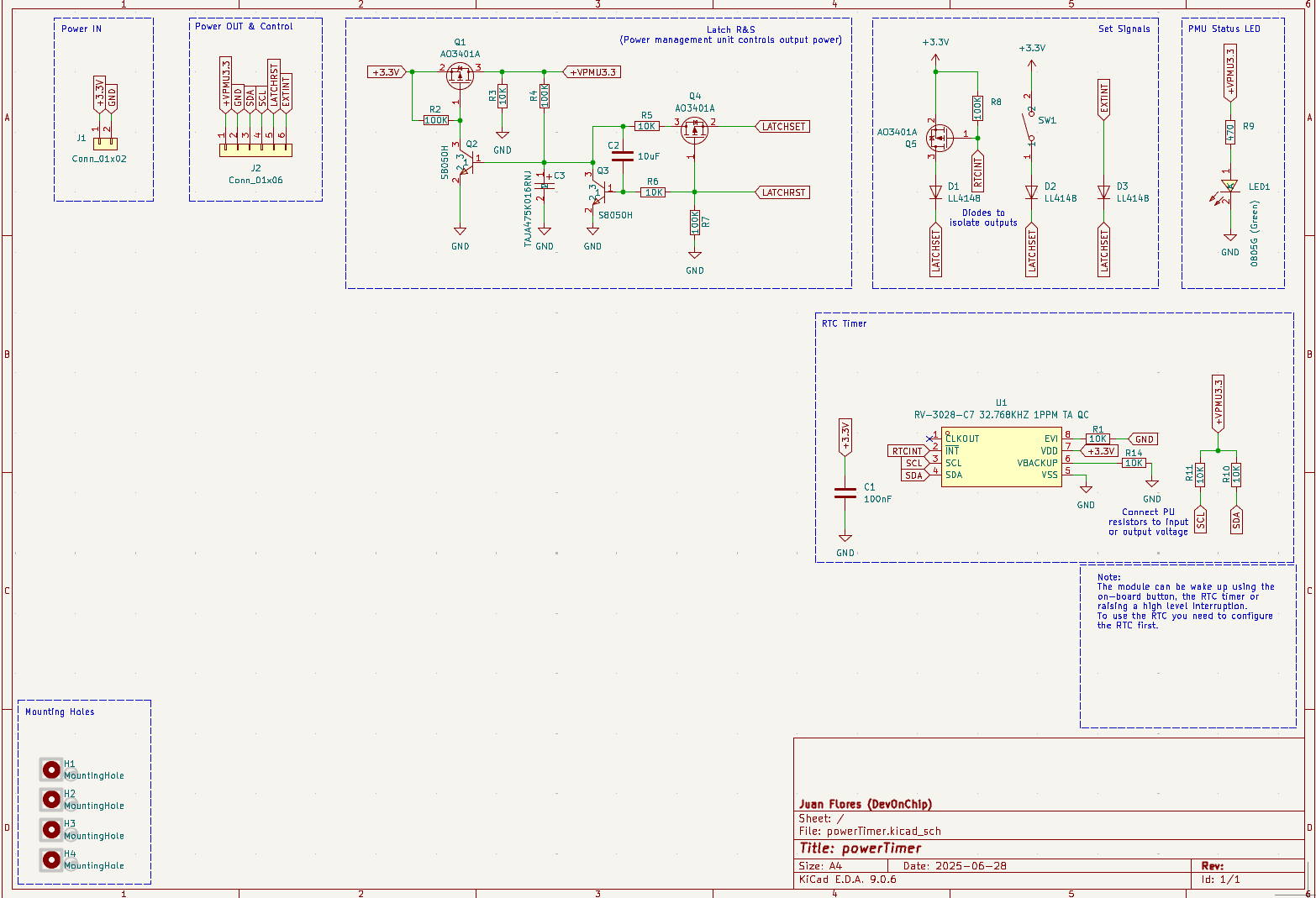
Schematic
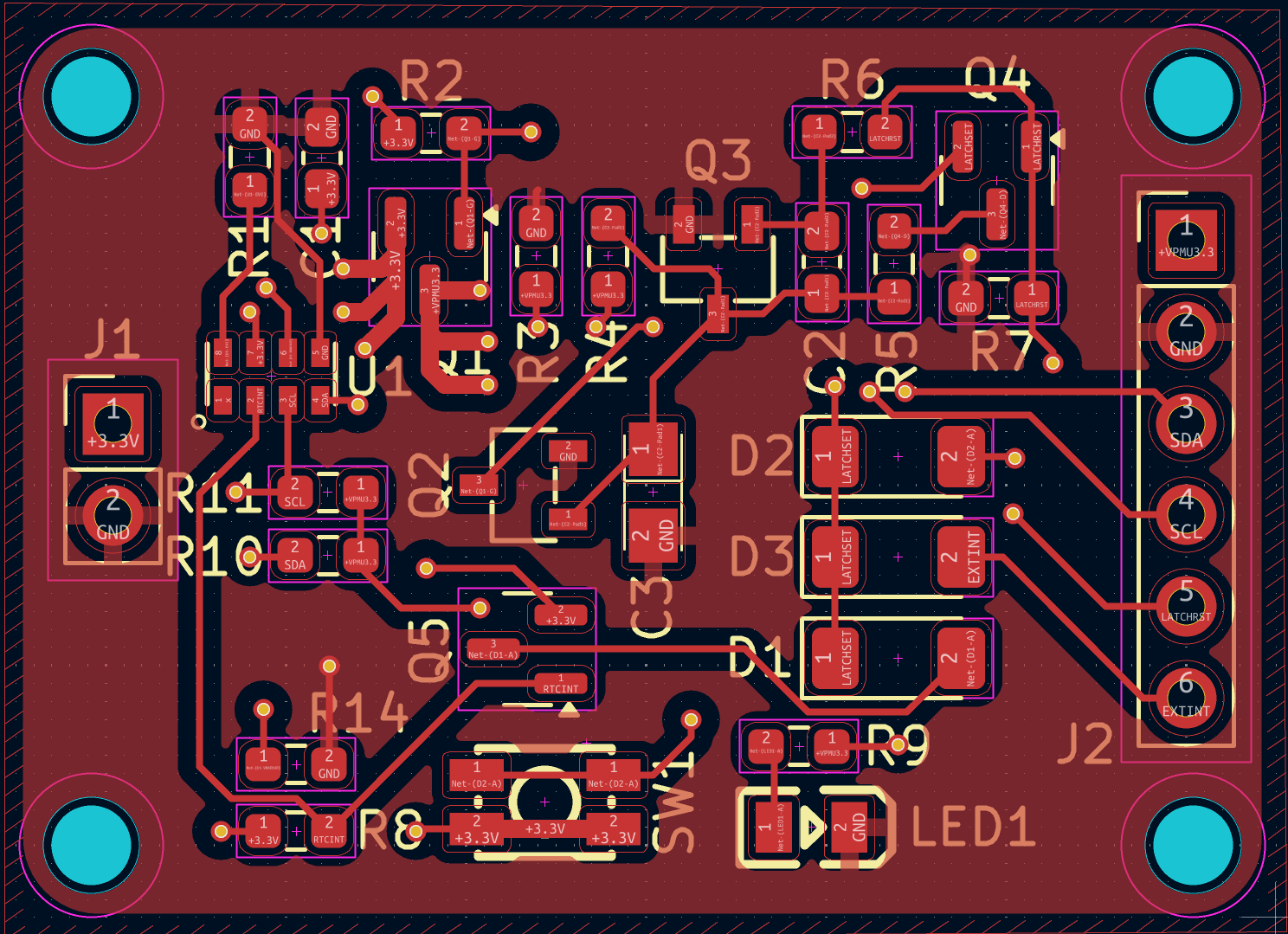
PCB Layout
Parts

33
QtyValueFootprintReferences
710KResistor_SMD:R_0603_1608Metric_Pad0.98x0.95mm_HandSolderR1, R3, R5, R6, R10, R11, R14
4100KResistor_SMD:R_0603_1608Metric_Pad0.98x0.95mm_HandSolderR2, R4, R7, R8
4MountingHoleMountingHole:MountingHole_2.2mm_M2_ISO7380H1, H2, H3, H4
3AO3401APackage_TO_SOT_SMD:SOT-23Q1, Q4, Q5
3LL4148Diode_SMD:D_MiniMELFD1, D2, D3
2S8050HRTCSwitch:SOT-23-3_L2.9-W1.6-P1.90-LS2.8-BRQ2, Q3
10805G (Green)RTCSwitch:LED0805-R-RDLED1
1100nFCapacitor_SMD:C_0603_1608Metric_Pad1.08x0.95mm_HandSolderC1
110uFCapacitor_SMD:C_0603_1608Metric_Pad1.08x0.95mm_HandSolderC2
1470Resistor_SMD:R_0603_1608Metric_Pad0.98x0.95mm_HandSolderR9
1Conn_01x02Connector_PinHeader_2.54mm:PinHeader_1x02_P2.54mm_VerticalJ1
1Conn_01x06Connector_PinHeader_2.54mm:PinHeader_1x06_P2.54mm_VerticalJ2
1LOGOLOGOG***
1RV-3028-C7 32.768KHZ 1PPM TA QCRTCSwitch:OSC-SMD_8P-L3.2-W1.5-P0.90-BLU1
1TAJA475K016RNJRTCSwitch:CASE-A_3216C3
1TS-1185EC-C-D-BRTCSwitch:SW-SMD_4P-L3.7-W3.0-P1.50-LS4.7SW1

Questions

How big is the PowerTimer PCB?

It measures 35.4 × 25.6 mm and has 2 copper layers, 1.6 mm thick.

What parts does the PowerTimer use?

33 parts, built around the AO3401A, LL4148, S8050H and TAJA475K016RNJ. The full list of its parts is on this page, with links to each part's symbol and footprint where PCBKit's library has them.

Where can I download the PowerTimer KiCad files?

From the jfm92/powerTimer repository on GitHub, at the commit this page was made from: the board is powerTimerPCB/powerTimer.kicad_pcb and its schematic powerTimerPCB/powerTimer.kicad_sch. PCBKit opens the board in the browser, with nothing to install.

Can I use the PowerTimer design in my own project?

Its repository states no licence, so its author keeps all rights: ask jfm92 before reusing the design.

Similar boards

  • 2 layers52 × 90 mmPlaced unrouted, the printed circuit board in 3D

    Placed unrouted

    nahhao74/QUIZ_Remote

    Every student holds a small pad with 16 keys and two 7-segment digits. The teacher opens a session on a laptop, students type the 6-digit room code, and answers arrive on the projector within a fraction of a second.

    127 partsMIT
  • 4 layers58.5 × 120.9 mmMainPCB, the printed circuit board in 3D

    MainPCB

    LEDs-by-glowingkitty/GlowTower

    A beautiful looking LED lamp for lighting up your home or setting the right mood at house parties - with animations that can react to music.

    155 parts9GPL-3.0
  • 2 layers34 × 96 mmGem solder, the printed circuit board in 3D

    Gem solder

    arlenko/gem-solder

    💎 DIY soldering iron controller

    114 parts12CERN-OHL-S-2.0
  • 2 layers27.9 × 34.3 mmGlowBand PCB, the printed circuit board in 3D

    GlowBand PCB

    LEDs-by-glowingkitty/GlowBand

    GlowBand is an exciting LED wristband. For dancing at parties and festivals, for long-time exposure photography, and for everyday situations that need some light.

    76 parts4MIT
  • 2 layers169.5 × 83.5 mmGlowSignMainPCB, the printed circuit board in 3D

    GlowSignMainPCB

    LEDs-by-glowingkitty/GlowSign

    A battery powered LED sign for your laptop, or where ever else you want to use it!

    130 parts1GPL-3.0
  • 2 layersDiodeplate, the printed circuit board in 3D

    Diodeplate

    janekc/diodeplate

    Plateshaped example PCB design for a portable partylamp

    85 partsGPL-3.0
  • 4 layers52 × 27 mmEcp5-mini, the printed circuit board in 3D

    Ecp5-mini

    kitspace-test-repos/kicad6-file-collection

    111 partsMIT
  • 2 layers40 × 40 mmEsp32Drone, the printed circuit board in 3D

    Esp32Drone

    HexaBitsEdu/ESP32-MiniDrone

    this project is a drone based on esp32 microcontroller and coreless DC motor

    83 parts2