
4 layers230 × 84.9 mm

 arlenko/gem-solder12
💎 DIY soldering iron controller
Gem solder is an open-source printed circuit board by arlenko, from the arlenko/gem-solder repository on GitHub, published under the CERN-OHL-S-2.0 licence. It is a 2-layer board of 34 × 96 mm with 114 parts on 96 nets, routed with 416 tracks and 99 vias.
It is built around the STM32F103C8T6, AD8629ARZ-REEL7 and MIC5219-3.3YM5-TR, with the HS91L02W2C01, FRC0603F5101TS and FRC0603F1501TS among its other parts. Its parts include 37 resistors, 26 capacitors, 12 diodes, 7 ICs and 6 connectors. It belongs with the STM32 boards of this library.


Gem Solder is an STM32-powered soldering iron controller for general-purpose C245 tips. It runs from a PD-compatible USB-C power source or from a DC power source of up to 24V, including 3S–6S battery packs. USB-C power delivery negotiates up to 20V.
The user interface features a 128×32 OLED display and two buttons. An RGB status LED gives visual feedback on the current operating mode.
The firmware is a fork of IronOS. It ships with the IronOS feature set including a UI available in 35 languages.
The firmware measures the heater resistance of the fitted tip to compute how much power it can handle — up to 140W from DC and up to 100W over USB-C. The delivered power therefore stays accurate across tips from different manufacturers.
Handle connector built into the 3D-printed housing. The housing carries the connector body, and a matching PCB piece drops into it, so the pins and wires are soldered to that piece instead of a special-purpose handle connector having to be sourced.
Check out the releases page!
Firmware and hardware are released separately, with tags prefixed fw- and hw-.
A firmware release ships every compiled firmware language plus the
bootloader. A hardware release ships the PCB fabrication
files, the bill of materials for sourcing components and cost
estimation, the interactive BOM for convenient PCB assembly by hand, and the STL
files for 3D printing the enclosure.
Get help and share your ideas on the discussions page!
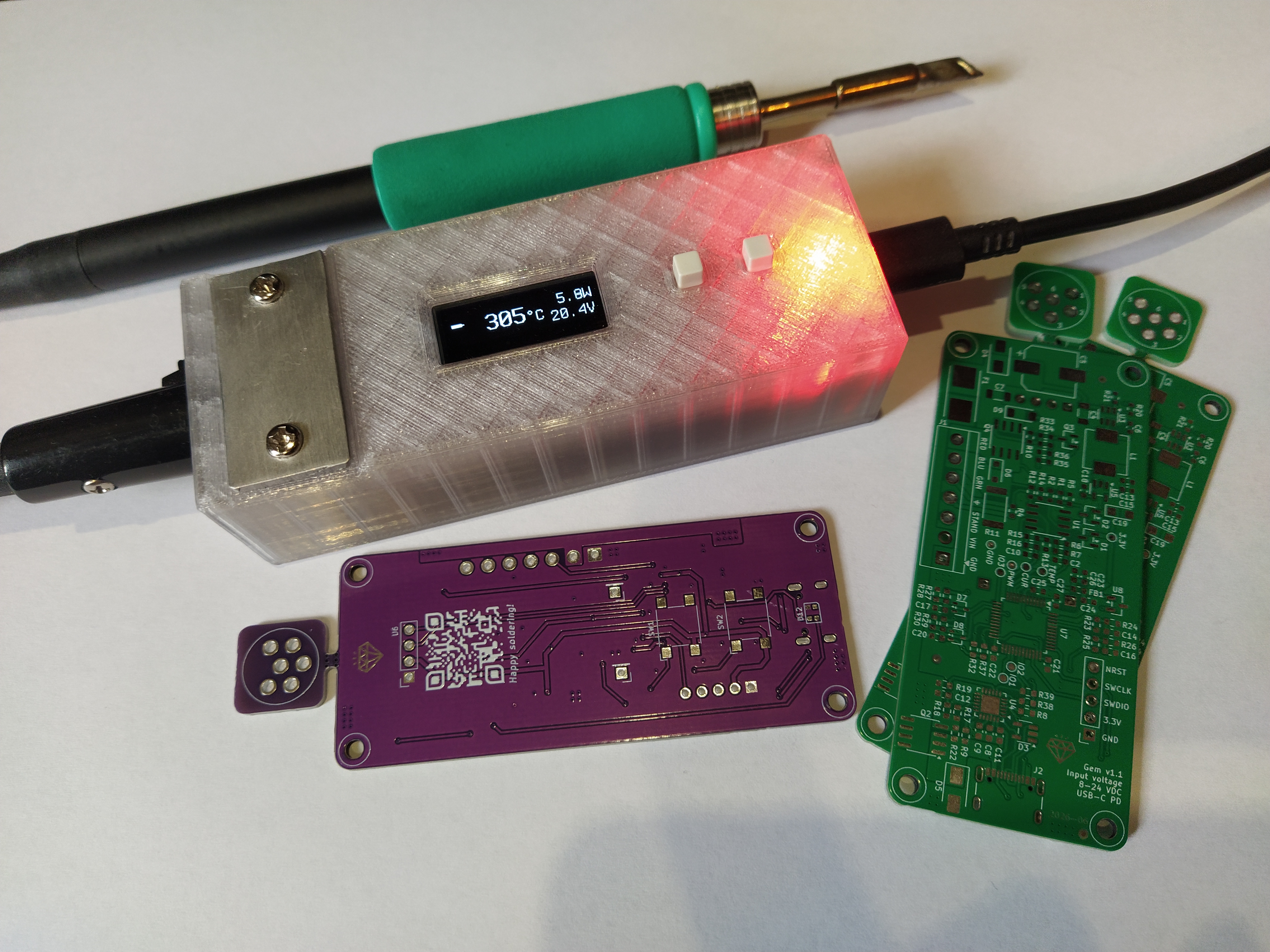
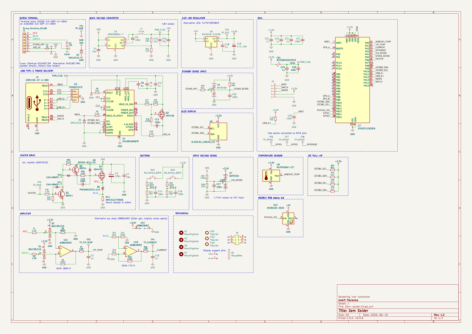
Gem Solder PCB was designed in KiCad. It's a two-layer board with a breakaway panel for a handle connector.
The heart of the device is the STM32F103C8T6 — an ARM Cortex-M3 MCU with 20 KB RAM and 64 KB flash. The STUSB4500QTR is a standalone PD sink controller, responsible for PD negotiation and VBUS management. It communicates with the MCU via I²C.
The AD8629ARZ is a high-precision, zero-drift operational amplifier that amplifies the microvolt-level signal from the tip thermocouple.
The tip heater power stage consists of a P-channel MOSFET and a discrete push-pull driver with a zener diode for maintaining the gate voltage at a safe operating level.
The AP63300WU-7 buck converter provides 4.6 V for biasing the WS2812 RGB LED, then a 3.3 V LDO regulator steps that down to supply the MCU, the OLED, the op-amp, and the ambient temperature sensor.
A 5 mΩ current sense resistor enables current measurement for accurate PWM duty calculation and tip presence detection.
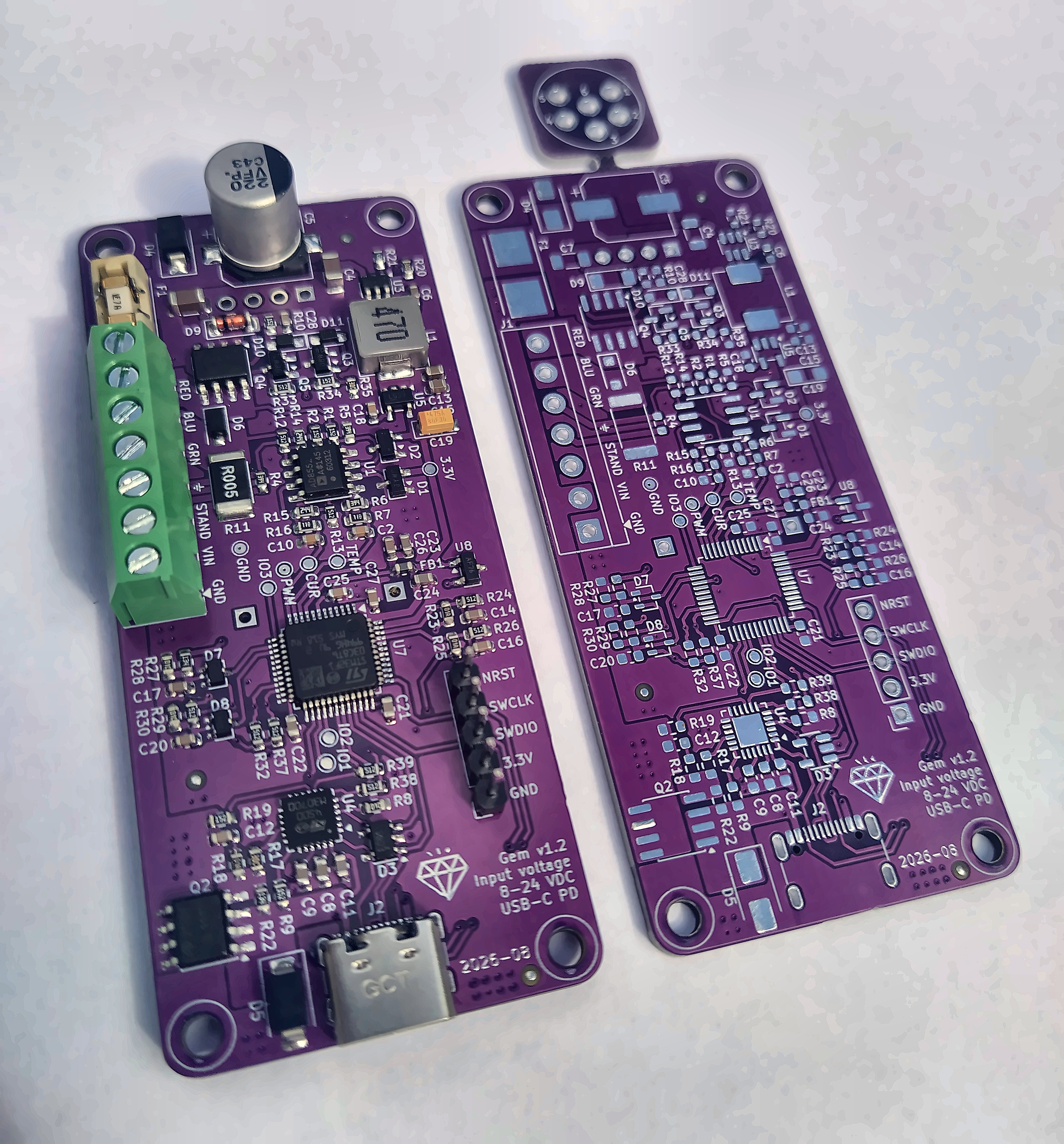
Here's a photo of the assembled and bare PCBs:
Print the enclosure in a semi-transparent material to keep the status LED visible.
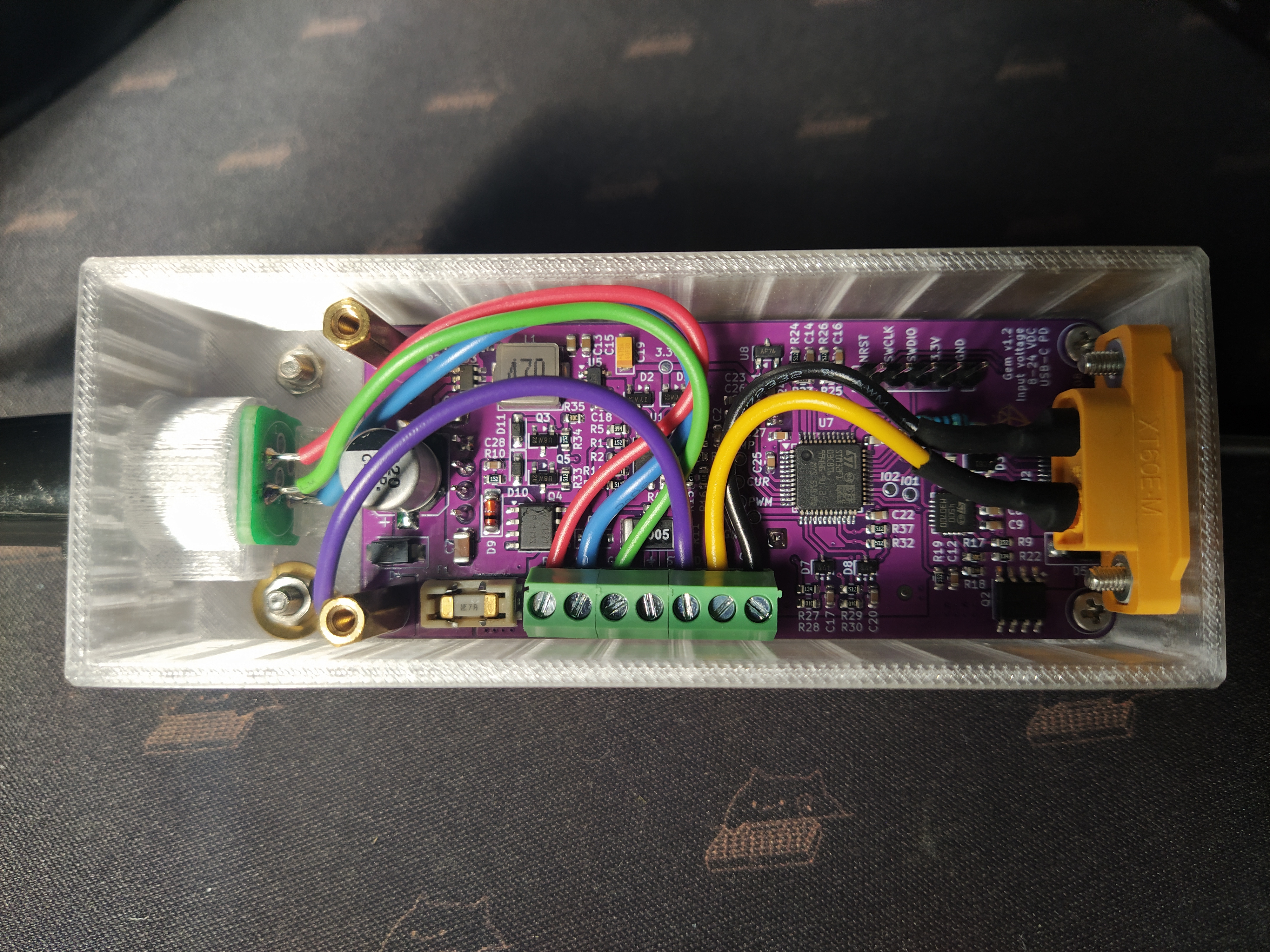
The 3D-printed enclosure has a built-in handle connector. Insert the connector PCB piece and plug in the handle before soldering the pins and wires.
The image below shows how the connector needs to be wired to the screw terminal:
The STM32F103 has no built-in USB bootloader, so the first flash needs an SWD programmer such as ST-LINK or DAPLink, wired to the 5-pin SWD header on the board.
Once the DFU bootloader has been flashed, all later updates run over a USB data cable using dfu-util.
The flashing instructions depend on the tool and software being used. A genuine ST-LINK can be used with STM32CubeIDE. DAPLink can be used with the OpenOCD CLI utility:
sudo openocd -f interface/cmsis-dap.cfg -c "adapter usb vid_pid 0x1a86 0x8012" \
          -f target/stm32f1x.cfg \
-c "program Firmware/Gem_EN.hex verify reset exit"Once the DFU bootloader has been flashed to the device using SWD, firmware can be flashed over a USB cable. To enter the DFU bootloader, click and hold button A and connect the USB cable. The IronOS splash logo should appear on the display, followed by a message reading "DFU bootloader". Then use dfu-util to upload the firmware:
sudo dfu-util -a 0 -D Firmware/Gem_EN.dfu -RTwo buttons control the device:
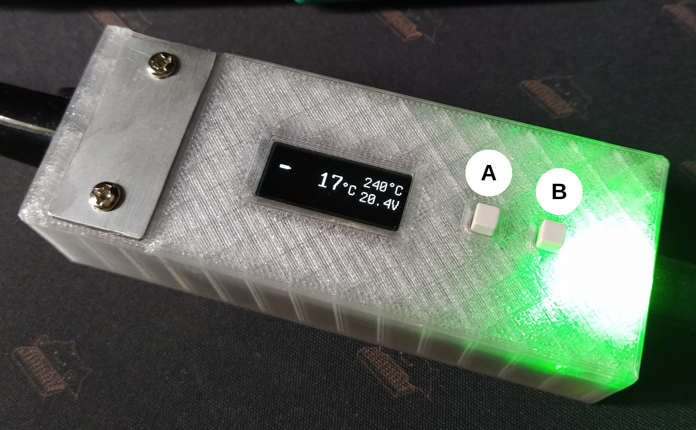
Their functions are as follows:
If an SMPS DC power supply is chosen as a power source, a SELV power supply with a floating output is required. Do not use power supply units whose DC output is connected to mains earth. Due to how the C245 tips are internally constructed, they provide a low-impedance path between the RED terminal, to which positive voltage is applied, and the GREEN terminal, which is connected to mains earth. While the Gem Solder's high-impedance path between the tip body and the earth terminal should not cause a short circuit, PELV power supplies are not recommended anyway.
⚠️ Do not connect USB-C and DC power sources simultaneously! USB and DC power paths are internally joined on the board, so one power source ends up connected straight to another.
Gem Solder PCB and enclosure designs are licensed under CERN Open Hardware Licence Version 2. Firmware code is covered by the GNU General Public License v3.0 license unless noted elsewhere.
| Qty | Value | Footprint | References |
|---|---|---|---|
| 10 | 100n | Capacitor_SMD:C_0603_1608Metric | C6, C12, C14, C16, C17, C20, C25, C26, C27, C28 |
| 9 | 5k1 | Resistor_SMD:R_0603_1608Metric | R12, R13, R24, R26, R29, R32, R37, R38, R39 |
| 7 | 1.5k | Resistor_SMD:R_0603_1608Metric | R1, R2, R9, R10, R19, R31, R34 |
| 7 | 1u | Capacitor_SMD:C_0603_1608Metric | C8, C9, C11, C21, C22, C23, C24 |
| 4 | MountingHole | MountingHole:MountingHole_2.7mm_M2.5_DIN965 | H1, H2, H3, H4 |
| 3 | 100R | Resistor_SMD:R_0603_1608Metric | R18, R23, R25 |
| 3 | 10k | Resistor_SMD:R_0603_1608Metric | R8, R28, R30 |
| 3 | 1n | Capacitor_SMD:C_0603_1608Metric | C2, C10, C18 |
| 3 | 20k | Resistor_SMD:R_0603_1608Metric | R17, R20, R35 |
| 3 | Fiducial | Fiducial:Fiducial_0.75mm_Mask1.5mm | FID1, FID2, FID3 |
| 2 | 10R | Resistor_SMD:R_0603_1608Metric | R7, R16 |
| 2 | 10u | Capacitor_SMD:C_1206_3216Metric | C4, C7 |
| 2 | 130k | Resistor_SMD:R_0603_1608Metric | R22, R27 |
| 2 | 1N4148WSF-7 | Diode_SMD:D_SOD-323_HandSoldering | D10, D11 |
| 2 | 22u | Capacitor_SMD:C_0603_1608Metric | C13, C15 |
| 2 | 240k | Resistor_SMD:R_0603_1608Metric | R14, R15 |
| 2 | 390k | Resistor_SMD:R_0603_1608Metric | R5, R6 |
| 2 | AO4435 | Package_SO:SOIC-8_3.9x4.9mm_P1.27mm | Q2, Q4 |
| 2 | BAT54SW | Package_TO_SOT_SMD:SOT-323_SC-70 | D7, D8 |
| 2 | BAV199.215 | Package_TO_SOT_SMD:SOT-23 | D1, D2 |
| 2 | BSR14 | Package_TO_SOT_SMD:SOT-23 | Q3, Q5 |
| 2 | Conn_01x01_Pin | Connector_PinHeader_2.54mm:PinHeader_1x01_P2.54mm_Vertical | J3, J4 |
| 2 | SMAJ24CA | Diode_SMD:D_SMA | D4, D5 |
| 2 | SW_Omron_B3FS | Button_Switch_SMD:SW_SPST_Omron_B3FS-100xP | SW1, SW2 |
| 1 | 1M | Resistor_SMD:R_0603_1608Metric | R4 |
| 1 | 220u | Capacitor_SMD:CP_Elec_8x10.5 | C5 |
| 1 | 4.7u 10V | Capacitor_Tantalum_SMD:CP_EIA-3216-18_Kemet-A | C19 |
| 1 | 47uH | Inductor_SMD:L_APV_APH0630 | L1 |
| 1 | 4k3 | Resistor_SMD:R_0603_1608Metric | R21 |
| 1 | 5.1k | Resistor_SMD:R_0603_1608Metric | R33 |
| 1 | 7A | Footprints:0154100DR | F1 |
| 1 | AD8629ARZ | Package_SO:SOIC-8_3.9x4.9mm_P1.27mm | U1 |
| 1 | AP63300WU-7 | Package_TO_SOT_SMD:TSOT-23-6 | U3 |
| 1 | BLM18AG331SN1D | Inductor_SMD:L_0603_1608Metric | FB1 |
| 1 | BZV55-B12.115 | Diode_SMD:D_MiniMELF | D9 |
| 1 | Conn_01x05_Socket | Connector_PinSocket_2.54mm:PinSocket_1x05_P2.54mm_Vertical | J5 |
| 1 | ESDA6V1SC5 | Package_TO_SOT_SMD:SOT-23-5 | D3 |
| 1 | LOGO | LOGO | G*** |
| 1 | MCP9700AT-ETT | Package_TO_SOT_SMD:SOT-23 | U8 |
| 1 | MIC5219-3.3YM5 | Package_TO_SOT_SMD:SOT-23-5 | U5 |
| 1 | MouseBite | Panelization:MouseBite-Slot_2.0x2.0mm_outset_D0.5mm_P0.85mm_3h | B1 |
| 1 | OLED0.91_128x32_I2C | Footprints:OLED_128x32_0.91 | U6 |
| 1 | PMEG6010CEH.115 | Diode_SMD:D_SOD-123F | D6 |
| 1 | RMF2512FTR005 | Resistor_SMD:R_2512_6332Metric | R11 |
| 1 | STM32F103C8T6 | Package_QFP:LQFP-48_7x7mm_P0.5mm | U7 |
| 1 | STUSB4500QTR | Footprints:QFN-24-1EP_4x4mm_P0.5mm_EP2.65x2.65mm | U4 |
| 1 | Screw_Terminal_01x06 | Footprints:TerminalBlock_DG350-3.5-07P-14-00AH_1x07_P3.50mm | J1 |
| 1 | TP_3V3 | TestPoint:TestPoint_Pad_D1.0mm | TP5 |
| 1 | TP_CURRENT | TestPoint:TestPoint_Pad_D1.0mm | TP4 |
| 1 | TP_GND | TestPoint:TestPoint_Pad_D1.0mm | TP1 |
| 1 | TP_GPIO1 | TestPoint:TestPoint_Pad_D1.0mm | TP6 |
| 1 | TP_GPIO2 | TestPoint:TestPoint_Pad_D1.0mm | TP7 |
| 1 | TP_GPIO3 | TestPoint:TestPoint_Pad_D1.0mm | TP8 |
| 1 | TP_PWM | TestPoint:TestPoint_Pad_D1.0mm | TP2 |
| 1 | TP_TIP_TEMP | TestPoint:TestPoint_Pad_D1.0mm | TP3 |
| 1 | USB4105-GF-A-060 | Connector_USB:USB_C_Receptacle_GCT_USB4105-xx-A_16P_TopMnt_Horizontal | J2 |
| 1 | WS2812B-2020 | Footprints:RGB_LED_WS2812B-2020_2.0x2.0mm | D12 |
| 1 | ~ | Footprints:Connector_Hirose_RPC1-12RB-6P(72) | J6 |
It measures 34 × 96 mm and has 2 copper layers, 1.6 mm thick.
114 parts, built around the STM32F103C8T6, AD8629ARZ-REEL7, MIC5219-3.3YM5-TR and HS91L02W2C01. The full list of its parts is on this page, with links to each part's symbol and footprint where PCBKit's library has them.
From the arlenko/gem-solder repository on GitHub, at the commit this page was made from: the board is hardware/Gem-solder.kicad_pcb and its schematic hardware/Gem-solder.kicad_sch. PCBKit opens the board in the browser, with nothing to install.
Its repository publishes it under the CERN-OHL-S-2.0 licence: you may reuse it on that licence's terms (keep the author's notice, and for a copyleft licence share your changes alike).

Polprzewodnikowy/SummerCart64
SummerCart64 - a fully open source N64 flashcart


Epicjoy/SC64
This project's hardware and casing are modified based on the SummerCart64 project.


holoindustry/AxxSolder_modded
Interested in purchasing an AxxSolder 3.2? On my website 5Dimensions you can purchase assembled and tested AxxSolder 3.2 boards with connectors and hardware.

lapalmaelettronica/Progetti
Una lista dei progetti che ho pubblicato su instagram, potete trovarci pcb, codici, schemo elettrici e stampe 3d!

nahhao74/QUIZ_Remote
Every student holds a small pad with 16 keys and two 7-segment digits. The teacher opens a session on a laptop, students type the 6-digit room code, and answers arrive on the projector within a fraction of a second.