2 layers63.8 × 95.8 mm

 JeyRunner/actonator10
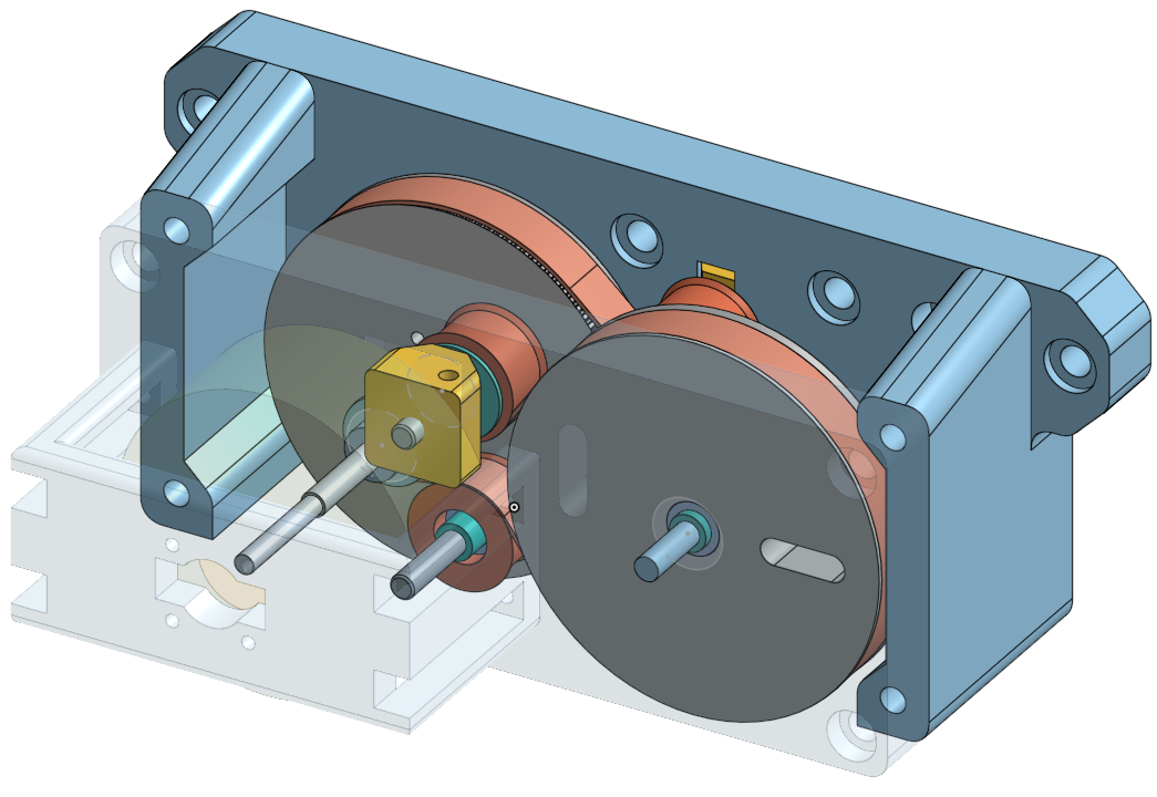
3D printable robot actuator with belt-driven gearbox and custom FOC driver board.
MotorDriver is an open-source printed circuit board by JeyRunner, from the JeyRunner/actonator repository on GitHub, published under the MIT licence. It is a 2-layer board of 100 × 70 mm with 177 parts on 110 nets, routed with 1,638 tracks and 242 vias.
It is built around the TJA1050T/CM, INA180A2IDBVR(LX) and L7805, with the UF4007, LNG03R031 and MUR460 among its other parts. Its parts include 51 resistors, 38 capacitors, 34 diodes, 13 ICs and 13 connectors. It belongs with the robots and motor control boards and the STM32 boards of this library.


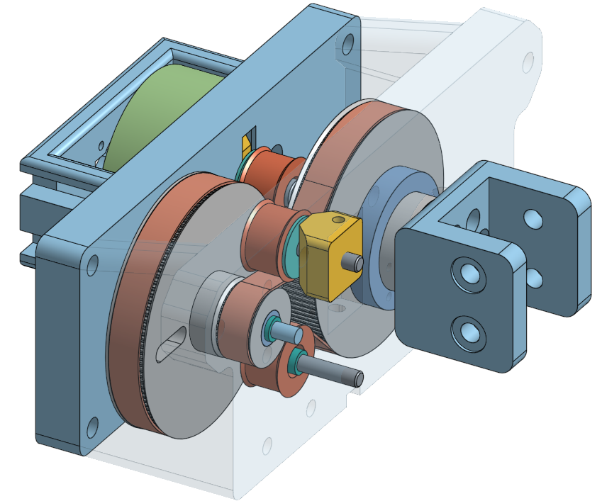
3D printable robot actuator with belt-driven gearbox and custom FOC driver board for the used BLDC motor. It uses the CAN SOT Protocol for the communication, which allows to not only send commands and receive state changes but also to set configuration parameters dynamically during runtime.
motor_driver/firmware: C++ firmware code for the stm32 microcontrollermotor_driver/can_client_lib: Contains the can bus communication protocol definition and host applications to configure and interface with the motor driver.
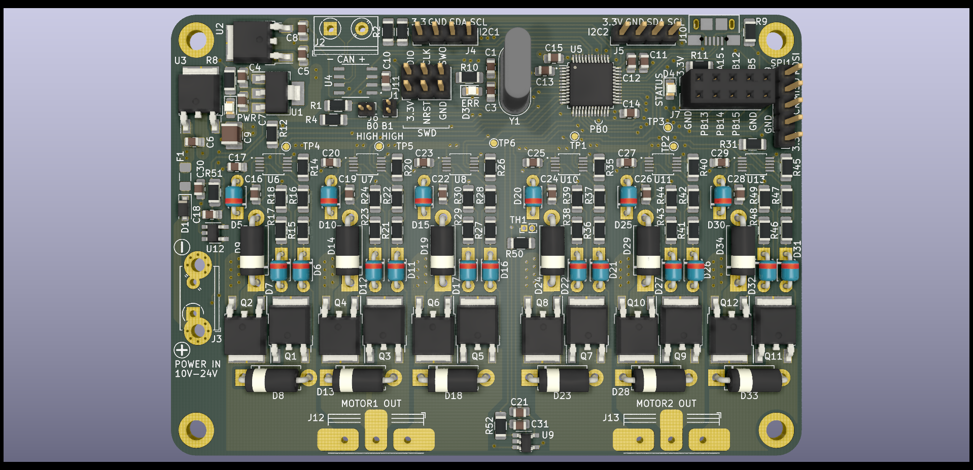
motorControllerCanProtocol.def.yaml: Contains the protocol definition.motor_driver/hardware: Kicad files with schematics for the board and PCB.motor_driver/hardware/output: Schematics, board layout and manufacturing files.gearbox: 3D printing stl files for the gearbox.This board is a dual channel brushless motor driver.
The design of the board can be found in the hardware subfolder.
In hardware/output are all generated files for all versions.
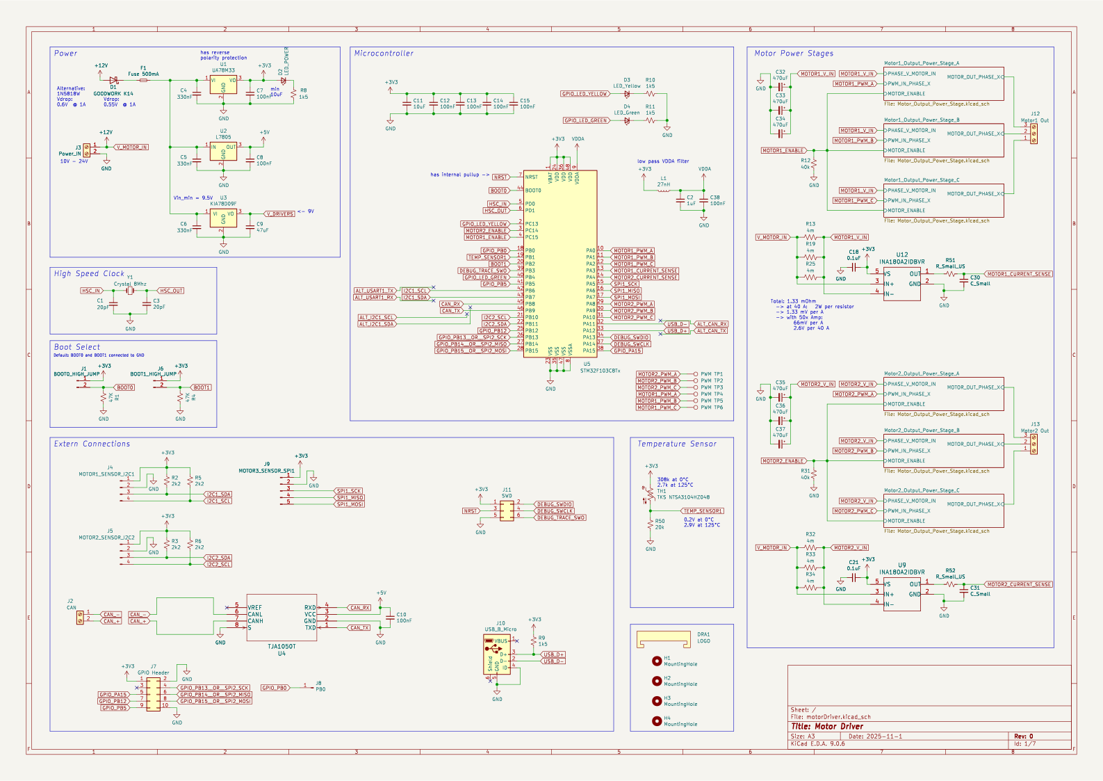
For the full schematic, see hardware/motorDriver/output/v0.0.1/schematic.pdf.
First look at motor_driver/can_client_lib/README.md to compile the communication lib and host control application. Then compile and flash the microcontroller firmware, see motor_driver/firmware/README.md.
| Qty | Value | Footprint | References |
|---|---|---|---|
| 18 | UF4007 | Diode_THT:D_T-1_P5.08mm_Horizontal | D5, D10, D11, D12, D15, D16, D17, D20, D21, D22, D25, D26, D27, D30, D31, D32 +2 |
| 12 | LNG03R031 | Package_TO_SOT_SMD:TO-252-2 | Q1, Q2, Q3, Q4, Q5, Q6, Q7, Q8, Q9, Q10, Q11, Q12 |
| 12 | MUR460 | added:D_DO-15_P10.16mm__H1.4mm_Horizontal | D8, D9, D13, D14, D18, D19, D23, D24, D28, D29, D33, D34 |
| 8 | 100nF | Capacitor_SMD:C_0805_2012Metric_Pad1.15x1.40mm_HandSolder | C7, C8, C10, C12, C13, C14, C15, C38 |
| 7 | 10uF | Capacitor_SMD:C_0805_2012Metric_Pad1.15x1.40mm_HandSolder | C11, C17, C20, C23, C25, C27, C29 |
| 6 | 10R | Resistor_SMD:R_1206_3216Metric_Pad1.42x1.75mm_HandSolder | R17, R23, R29, R38, R43, R48 |
| 6 | 22R | Resistor_SMD:R_1206_3216Metric_Pad1.42x1.75mm_HandSolder | R18, R24, R30, R39, R44, R49 |
| 6 | 3.3R | Resistor_SMD:R_1206_3216Metric_Pad1.42x1.75mm_HandSolder | R16, R22, R28, R37, R42, R47 |
| 6 | 470nF | Capacitor_SMD:C_0805_2012Metric_Pad1.15x1.40mm_HandSolder | C16, C19, C22, C24, C26, C28 |
| 6 | 470uF | Capacitor_SMD:CP_Elec_10x10.5 | C32, C33, C34, C35, C36, C37 |
| 6 | 47R | Resistor_SMD:R_1206_3216Metric_Pad1.42x1.75mm_HandSolder | R14, R20, R26, R35, R40, R45 |
| 6 | 4m | Resistor_SMD:R_2512_6332Metric_Pad1.52x3.35mm_HandSolder | R13, R19, R25, R32, R33, R34 |
| 6 | 5R | Resistor_SMD:R_1206_3216Metric_Pad1.42x1.75mm_HandSolder | R15, R21, R27, R36, R41, R46 |
| 6 | LM5106MM_NOPB | lm5106:LM5106MM_slash_NOPB | U6, U7, U8, U10, U11, U13 |
| 6 | PWM | TestPoint:TestPoint_Pad_D1.0mm | TP1, TP2, TP3, TP4, TP5, TP6 |
| 4 | 1k5 | Resistor_SMD:R_1206_3216Metric_Pad1.42x1.75mm_HandSolder | R8, R9, R10, R11 |
| 4 | 2k2 | Resistor_SMD:R_1206_3216Metric_Pad1.42x1.75mm_HandSolder | R2, R3, R5, R6 |
| 4 | MountingHole | MountingHole:MountingHole_3.2mm_M3_DIN965_Pad | H1, H2, H3, H4 |
| 3 | 330nF | Capacitor_SMD:C_0805_2012Metric_Pad1.15x1.40mm_HandSolder | C4, C5, C6 |
| 2 | 0.1uF | Capacitor_SMD:C_0805_2012Metric_Pad1.15x1.40mm_HandSolder | C18, C21 |
| 2 | 20pF | Capacitor_SMD:C_0805_2012Metric_Pad1.15x1.40mm_HandSolder | C1, C3 |
| 2 | 40k | Resistor_SMD:R_1206_3216Metric_Pad1.42x1.75mm_HandSolder | R12, R31 |
| 2 | 47K | Resistor_SMD:R_1206_3216Metric_Pad1.42x1.75mm_HandSolder | R1, R4 |
| 2 | C_Small | Capacitor_SMD:C_0805_2012Metric_Pad1.15x1.40mm_HandSolder | C30, C31 |
| 2 | INA180A2IDBVR | Package_TO_SOT_SMD:SOT-23-5_HandSoldering | U9, U12 |
| 2 | R_Small_US | Resistor_SMD:R_1206_3216Metric_Pad1.42x1.75mm_HandSolder | R51, R52 |
| 1 | 1uF | Capacitor_SMD:C_0805_2012Metric_Pad1.15x1.40mm_HandSolder | C2 |
| 1 | 20k | Resistor_SMD:R_1206_3216Metric_Pad1.42x1.75mm_HandSolder | R50 |
| 1 | 27nH | Inductor_SMD:L_0603_1608Metric_Pad1.05x0.95mm_HandSolder | L1 |
| 1 | 47uF | Capacitor_SMD:C_1210_3225Metric_Pad1.42x2.65mm_HandSolder | C9 |
| 1 | BOOT0_HIGH_JUMP | added:PinHeader_1x02_P1.27mm_Vertical__smallerOutline | J1 |
| 1 | BOOT1_HIGH_JUMP | added:PinHeader_1x02_P1.27mm_Vertical__smallerOutline | J6 |
| 1 | CAN | added:TerminalBlock_RND_205-00045_1x02_P5.00mm_Horizontal | J2 |
| 1 | Crystal 8Mhz | Crystal:Crystal_HC50_Vertical | Y1 |
| 1 | Fuse 500mA | Fuse:Fuse_1206_3216Metric_Pad1.42x1.75mm_HandSolder | F1 |
| 1 | G*** | kibuzzard-642D7167 | kibuzzard-642D7167 |
| 1 | GOODWORK K14 | Diode_SMD:D_SOD-123F | D1 |
| 1 | GPIO Header | Connector_PinSocket_2.54mm:PinSocket_2x05_P2.54mm_Vertical | J7 |
| 1 | KIA78D09F | Package_TO_SOT_SMD:TO-252-2 | U3 |
| 1 | L7805 | Package_TO_SOT_SMD:TO-252-2 | U2 |
| 1 | LED_Green | LED_SMD:LED_0805_2012Metric_Pad1.15x1.40mm_HandSolder | D4 |
| 1 | LED_POWER | LED_SMD:LED_0805_2012Metric_Pad1.15x1.40mm_HandSolder | D2 |
| 1 | LED_Yellow | LED_SMD:LED_0805_2012Metric_Pad1.15x1.40mm_HandSolder | D3 |
| 1 | LOGO | logo:logo | DRA1 |
| 1 | MOTOR1_SENSOR_I2C1 | Connector_PinHeader_2.54mm:PinHeader_1x04_P2.54mm_Vertical | J4 |
| 1 | MOTOR2_SENSOR_I2C2 | Connector_PinHeader_2.54mm:PinHeader_1x04_P2.54mm_Vertical | J5 |
| 1 | MOTOR3_SENSOR_SPI1 | Connector_PinHeader_2.54mm:PinHeader_1x05_P2.54mm_Vertical | J9 |
| 1 | Motor1 Out | added:TerminalBlock_RND_205-00046_1x03_P5.00mm_Horizontal__extended_pads | J12 |
| 1 | Motor2 Out | added:TerminalBlock_RND_205-00046_1x03_P5.00mm_Horizontal__extended_pads | J13 |
| 1 | PB0 | TestPoint:TestPoint_Pad_D1.5mm | J8 |
| 1 | Power_IN | added:TerminalBlock_RND_205-00045_1x02_P5.00mm_Horizontal___with_holes | J3 |
| 1 | STM32F103C8Tx | Package_QFP:LQFP-48_7x7mm_P0.5mm | U5 |
| 1 | SWD | Connector_PinHeader_2.54mm:PinHeader_2x03_P2.54mm_Vertical | J11 |
| 1 | TJA1050T | tja1050t:TJA1050T | U4 |
| 1 | TKS NTSA3104HZ048 | added:TH_2PIN_1.27mm | TH1 |
| 1 | UA78M33 | Package_TO_SOT_SMD:SOT-223-3_TabPin2 | U1 |
| 1 | USB_B_Micro | micro_usb:XKB_U254-051T-4BH83-F1S | J10 |
It measures 100 × 70 mm and has 2 copper layers, 1.6 mm thick.
177 parts, built around the TJA1050T/CM, INA180A2IDBVR(LX), L7805 and UF4007. The full list of its parts is on this page, with links to each part's symbol and footprint where PCBKit's library has them.
From the JeyRunner/actonator repository on GitHub, at the commit this page was made from: the board is motor_driver/hardware/motorDriver.kicad_pcb and its schematic motor_driver/hardware/Motor_Output_Power_Stage.kicad_sch. PCBKit opens the board in the browser, with nothing to install.
Its repository publishes it under the MIT licence: you may reuse it on that licence's terms (keep the author's notice, and for a copyleft licence share your changes alike).


BreathOfHope/Respirator-2
Respirator-2 takes the knowledge we gained in building the RespiratorApparatus to build a production ready version, that can be manufactured in an industrial setting.

hoffmannpablorodrigo/electroporator-esope
Electroporator hardware with esope protocol


UAA-F14/PCBs-Design
Power electronics PCB coursework — SCR controller, buck converter, Class D amplifier, DC-AC inverter, and a protected power supply Resources
