
2 layers59 × 22 mm

Tiny breadboard compatible development board based on either ATTiny414, ATTiny814 or ATTiny1614
X14 dev is an open-source printed circuit board by jenschr, from the jenschr/ATTinyX14-development-board repository on GitHub, published under the MIT licence. It is a 2-layer board of 39.4 × 16.2 mm with 23 parts on 32 nets, routed with 228 tracks and 19 vias.
It is built around the CH340E, AP2112K-3.3TRG1 and TS-1088-AR02016, with the TYPE-C-31-M-14 among its other parts. Its parts include 6 resistors, 4 connectors, 3 capacitors, 3 ICs and 2 inductors. It belongs with the AVR (ATmega, ATtiny) boards of this library.


Tiny breadboard compatible development board that can contain either an ATTiny414, ATTiny814 or ATTiny1614 - depending on your need for Flash memory. This repo contains the complete Kicad design files under an MIT license as well as documentation, pinout & images of the verified design. I'm a consultant based in Oslo/Norway, so get in touch if you need custom hardware based on ATTiny or other MCUs.
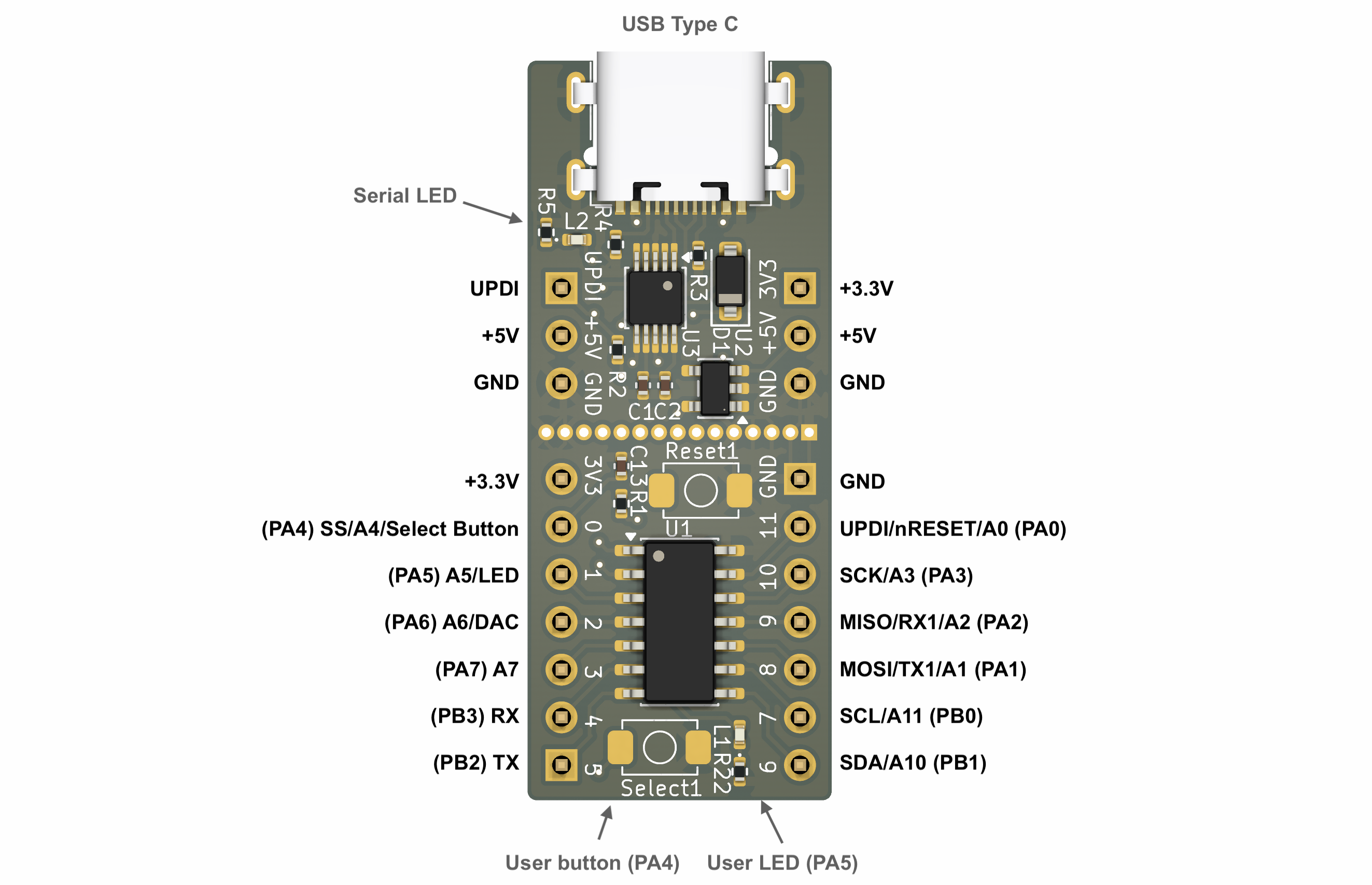
This nifty little microcontroller paired with the CH340 serial chip, makes for a very compact development board. Due to it's tiny size, you have 3 rows on each side of the breadboard to connect jumper wires to. When used with Spence Konde's brilliant megaTinyCore, this is very smooth to use for prototyping.
The board has a builtin LED on (PA5) and a button (PA4) for testing. The Serial chip has a LED on the TX line, so you can visually inspect when programming is done and finished. My primary reason for looking at this chip series was the 8-bit DAC output on PA6. Very few MCU's in this price range has a builtin DAC, so it is very handy for many types projects such as controlling devices based on voltage. One such example is controlling 0-10V motors/fans by just adding a small OpAmp circuit.
Some things to note:
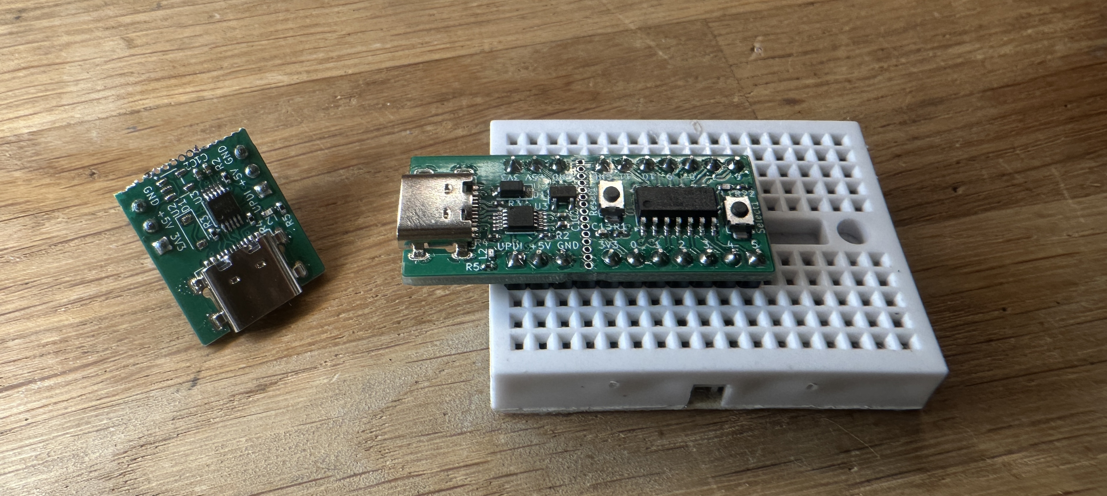
The UPDI programmer can be cut away, so you can use the MCU and programmer separately. In that case, the MCU must be powered separately, since the 3.3V regulator sits on the UPDI Programmer.
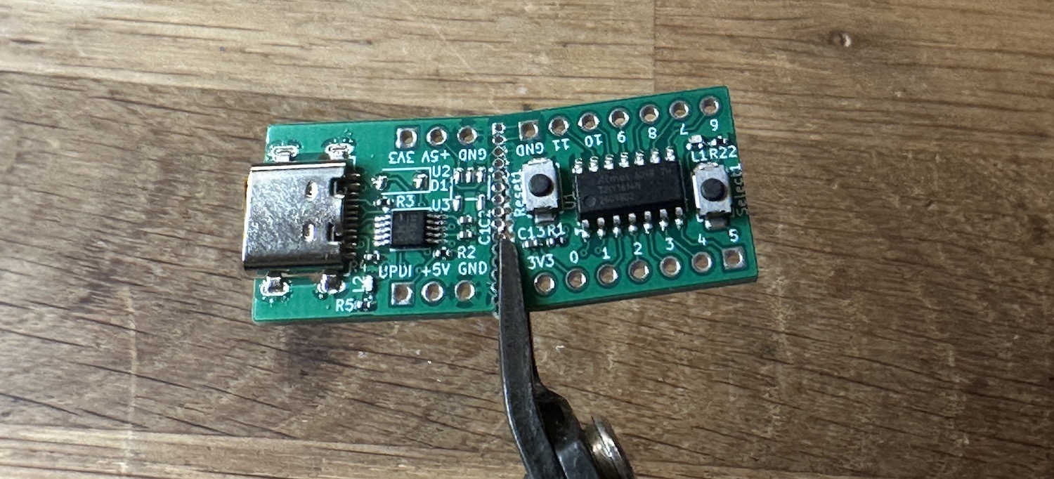
One drawback is that the setup does not allow for direct Serial debugging. You have to connect a separate Serial Converter/Adapter (like this one or anything similar) to use Arduino's Serial.
| Qty | Value | Footprint | References |
|---|---|---|---|
| 3 | 0.1uF | Capacitor_SMD:C_0402_1005Metric | C1, C2, C13 |
| 3 | 1k | Resistor_SMD:R_0402_1005Metric | R2, R5, R22 |
| 2 | 5.1k | Resistor_SMD:R_0402_1005Metric | R3, R4 |
| 2 | Butt | LCSC-button:TS-1088-AR02016 | Reset1, Select1 |
| 2 | Conn_01x07_Pin | Connector_PinHeader_2.54mm:PinHeader_1x07_P2.54mm_Vertical | J2, J3 |
| 1 | 180R | Resistor_SMD:R_0402_1005Metric | R1 |
| 1 | AP2112K-3.3 | Package_TO_SOT_SMD:SOT-23-5 | U2 |
| 1 | ATTINY1614-SSNR | Package_SO:SOIC-14_3.9x8.7mm_P1.27mm | U1 |
| 1 | CH340E | Package_SO:MSOP-10_3x3mm_P0.5mm | U3 |
| 1 | Conn_01x15_Pin | ToyTronics:PinHeader_1x16_P1.00mm_Vertical | J4 |
| 1 | D | Diode_SMD:D_SOD-123 | D1 |
| 1 | LED | LED_SMD:LED_0402_1005Metric | L1 |
| 1 | Prog | Connector_PinHeader_2.54mm:PinHeader_1x03_P2.54mm_Vertical | PROG2 |
| 1 | RED | LED_SMD:LED_0402_1005Metric | L2 |
| 1 | USB_C_Receptacle_USB2.0 | LCSC-button:TYPE-C-31-M-14 | J1 |
| 1 | Volt | Connector_PinHeader_2.54mm:PinHeader_1x03_P2.54mm_Vertical | VOLT1 |

Envious-Data/Env-KB
A custom mechanical keyboard inspired by the CFTKB Mysterium utilizing the Raspberry Pi Pico

plinkysynth/plinky_public
a public release of the plinky sw and hw

stanleyondrus/ILDAWaveX16
ILDAWaveX16 is an open-source, high-resolution, wireless laser DAC with SD-card playback, network control, and ILDA output.


eggsworks/le-oeuf-v2
An ultra-low profile (Kailh PG1316S) keyboard inspired by Le Chiffre.


Envious-Data/Env-ChocV2TKL
A Compact TKL layout utilizing Choc V2s and a Elite-C
It measures 39.4 × 16.2 mm and has 2 copper layers, 1.6 mm thick.
23 parts, built around the CH340E, AP2112K-3.3TRG1, TS-1088-AR02016 and TYPE-C-31-M-14. The full list of its parts is on this page, with links to each part's symbol and footprint where PCBKit's library has them.
From the jenschr/ATTinyX14-development-board repository on GitHub, at the commit this page was made from: the board is pcb/X14_dev.kicad_pcb and its schematic pcb/X14_dev.kicad_sch. PCBKit opens the board in the browser, with nothing to install.
Its repository publishes it under the MIT licence: you may reuse it on that licence's terms (keep the author's notice, and for a copyleft licence share your changes alike).