2 layers40 × 18.5 mm
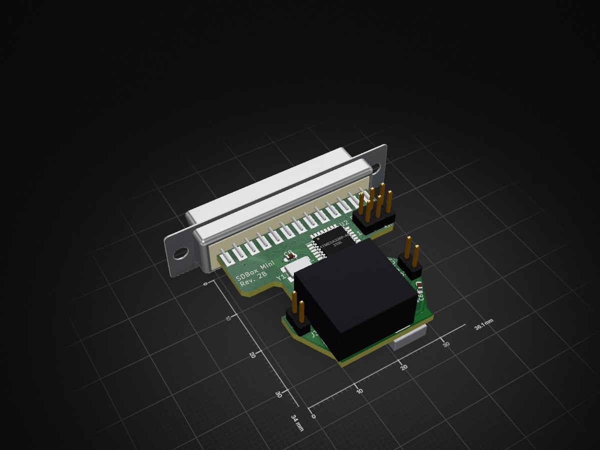
 jbilander/SDBox-Mini28
SDBox Mini for Amiga, compatible with the new updated card-detect firmware
SDBox Mini is an open-source printed circuit board by jbilander, from the jbilander/SDBox-Mini repository on GitHub, published under the GPL-3.0 licence. It is a 2-layer board of 36.1 × 34 mm with 29 parts on 48 nets, routed with 322 tracks and 39 vias.
It is built around the ATMEGA328P-AU, 74AHCT1G126GV and 74LVC3G17DP, with the LM1117-3.3 among its other parts. Its parts include 9 capacitors, 6 resistors, 4 ICs, 4 connectors and 2 diodes. It belongs with the AVR (ATmega, ATtiny) boards of this library.


SDBox in a standard DB25 plastic shell
This version is superseded by the new SDBox-v3 here: https://github.com/jbilander/SDBox-v3
Rev. 2B


Video:
https://drive.google.com/file/d/1fLwmIyUeHZX4sln5bpJfz5QkDGD-QTOf/view?usp=sharing
+5V taken from floppy port with this USB-C dongle
https://github.com/jbilander/Amiga_DB23_to_USB_C_power_only_adapter
Rev. 2A


This hardware uses the firmware written by Niklas Ekström, available here...
https://github.com/niklasekstrom/amiga-par-to-spi-adapter
...or use my fork if you also want the Activity LED to blink (it also includes a batch-script flashSDBoxMini.bat for flashing the Mini)
https://github.com/jbilander/amiga-par-to-spi-adapter
Connecting the Arduino to program the SDBox Mini
(Programmer)
Arduino as ISP - SDBox Mini
------------------------------------
D13 (SPI) SCK  - Pin 3 (ICSP) SCK
D12 (SPI) MISO - Pin 1 (ICSP) MISO
D11 (SPI) MOSI - Pin 4 (ICSP) MOSI
D10 (SPI) SS   - Pin 5 (ICSP) /RESET
          5V   - Pin 2 VCC
          GND  - Pin 6 GND
On the Nano V3 the pins on the ICSP-header can be utilized connected like below. There is no need to solder an ICSP-header on the mini, you can just hold the connector against the footprint while programming.


To use the Arduino Nano as ISP it first has to be flashed with the ArduinoISP-sketch which is available under File->Examples in the Arduino IDE, or you can use the attached batch-script flash_Arduino_as_ISP.bat and binary hex ArduinoISP.ino.arduino_standard.hex I have put them in a zip-file under Releases ArduinoISP.zip. Alter the com port in the script file to suit your machine and execute it from a command-prompt. Now you are ready to flash the SDBox-Mini via the Arduino.
This requires that you already have built the main.hex file in the avr-folder, then execute flashSDBoxMini.bat from a command prompt:
C:\Users\Jorgen\Projects\amiga-par-to-spi-adapter\avr>flashSDBoxMini.batC:\Users\Jorgen\Projects\amiga-par-to-spi-adapter\avr>"C:\Program Files (x86)\Arduino\hardware\tools\avr/bin/avrdude" -C "C:\Program Files (x86)\Arduino\hardware\tools\avr/etc/avrdude.conf" -v -pm328p -cstk500v1 -PCOM4 -b19200 -Uflash:w:main.hex:i -Ulfuse:w:0xe6:m -Uhfuse:w:0xdf:m -Uefuse:w:0xfc:m
avrdude: Version 6.3-20190619
Copyright (c) 2000-2005 Brian Dean, http://www.bdmicro.com/
Copyright (c) 2007-2014 Joerg Wunsch
System wide configuration file is "C:\Program Files (x86)\Arduino\hardware\tools\avr/etc/avrdude.conf"
Using Port : COM4
Using Programmer : stk500v1
Overriding Baud Rate : 19200
AVR Part : ATmega328P
Chip Erase delay : 9000 us
PAGEL : PD7
BS2 : PC2
RESET disposition : dedicated
RETRY pulse : SCK
serial program mode : yes
parallel program mode : yes
Timeout : 200
StabDelay : 100
CmdexeDelay : 25
SyncLoops : 32
ByteDelay : 0

sudo apt install avrdudeNow copy the default config file to a new file under /home/pi
cp /etc/avrdude.conf ~/avrdude_gpio.confAdd this entry last in the file using your editor (vim or nano) and save the file:
#------------------------------------------------------------
# Linux GPIO configuration for avrdude
# Change the lines below to the GPIO pins connected to the AVR
#------------------------------------------------------------
programmer
    id        = "pi_1";
    desc      = "Use the Linux sysfs interface to bitbang GPIO lines";
    type      = "linuxgpio";
    reset     = 12;
    sck       = 24;
    mosi      = 23;
    miso      = 18;
;
Now cd into /home/pi and make the script-file executable:
chmod 755 ./flashSDBoxMini.shWith all jumper-wires connected and main.hex built, run the script flashSDBoxMini.sh (OR type the line below and hit enter)
sudo avrdude -C ~/avrdude_gpio.conf -c pi_1 -v -p m328p -Uflash:w:main.hex:i -Ulfuse:w:0xe6:m -Uhfuse:w:0xdf:m -Uefuse:w:0xfc:mpi@raspberrypi:~ $ ./flashSDBoxMini.shavrdude: Version 6.3-20171130
Copyright (c) 2000-2005 Brian Dean, http://www.bdmicro.com/
Copyright (c) 2007-2014 Joerg Wunsch
System wide configuration file is "/home/pi/avrdude_gpio.conf"
User configuration file is "/root/.avrduderc"
User configuration file does not exist or is not a regular file, skipping
Using Port : unknown
Using Programmer : pi_1
AVR Part : ATmega328P
Chip Erase delay : 9000 us
PAGEL : PD7
BS2 : PC2
RESET disposition : dedicated
RETRY pulse : SCK
serial program mode : yes
parallel program mode : yes
Timeout : 200
StabDelay : 100
CmdexeDelay : 25
SyncLoops : 32
ByteDelay : 0
PollIndex : 3One caveat to keep in mind when building and programming Rev.2A (the first revision of the Mini) is the flashing of the fw can't be done with U4 chip in place as it drives/conflicts with MISO on ICSP (In-Circuit Serial Programming). For Rev. 2B PCB use 74AHCT1G126 instead of 74LVC1G17, same package/footprint. This solves the flashing conflict problem. You put a Jumper-shunt on JP1 (on Rev 2B PCB) while flashing and remove it afterwards.
Start with the 16 MHz Crystal, C8, C9 and the ATMega328P.


At this point you should be able to flash the Firmware to the ATMega using either an Arduino as ISP or a Raspberry Pi.
Continue with the rest of the components on the front side, and then the back side. I usually pre-tin the C1 pads and use hot air to put the C1-Capacitor in place.


Verify the Micro USB-jack and the voltage levels...


Now it's time to drill the holes for the LEDs, begin with a 1 mm drill and then step up to 2 mm and finally 3 mm. Be very careful when drilling to get a nice clean 3mm hole, it's very easy to slip and the hole gets oval or offset.


Short video showing copying a 8 MB file from the HD to the SD-card on my A1200. +5V to power the SDBox I nicked from the floppy port DB23->microUSB (Howto make such a cable here ).
Video:
https://i.imgur.com/mF9Bp4C.mp4


Download Amiga.zip from Releases.
fat95 into L: (download from Aminet)SD0 and SD0.info into Devs: (from Amiga.zip)spisd.device into Devs: (from Amiga.zip)Mount_SDCARD and Mount_SDCARD.info anywhere on your HD or floppy disk.Mount_SDCARD icon.Disk icon should now appear on the Workbench screen.
Happy Hackin´
| Position | Name/Value | Package | Notes |
|---|---|---|---|
| U4 | 74AHCT1G126 | 5-TSSOP, SC-70-5, SOT-353 (2.0 mm × 1.25mm) | Single non-inverting buffer 74AHCT1G126 (instead of 74LVC1G17) https://www.mouser.com/ProductDetail/Nexperia/74AHCT1G126GW125?qs=P62ublwmbi%252BsCpFPoi5fgw%3D%3D |
| JP1 | 2.0mm two-pin header + jumper-shunt | ||
| R6 | 10k Ohm Resistor | 0603 SMD | Pull-up resistor for OE pin 1 of 74AHCT1G126 |
| Position | Name/Value | Package | Notes |
|---|---|---|---|
| U1 | LM1117-3.3 | SOT-223 | Low-Dropout Linear Regulator 3.3 Volt |
| U2 | ATMega328P-AU | TQFP-32_7x7mm_P0.8mm | 8-bit AVR Microcontroller with 32K Bytes In-System Programmable Flash |
| U3 | 74LVC3G17 | TSSOP-8_3x3mm_P0.65mm | Triple non-inverting Schmitt trigger with 5V tolerant input https://www.digikey.se/product-detail/en/nexperia-usa-inc/74LVC3G17DP-125/1727-5998-1-ND/2753830 |
| U4 | 74LVC1G17 | 5-TSSOP, SC-70-5, SOT-353 (2.0 mm × 1.25mm) | Single non-inverting Schmitt trigger https://www.digikey.se/product-detail/en/nexperia-usa-inc/74LVC1G17GW-125/1727-4117-1-ND/1965408 For Rev. 2B PCB use 74AHCT1G126 instead of 74LVC1G17, same package/footprint: https://www.mouser.com/ProductDetail/Nexperia/74AHCT1G126GW125?qs=P62ublwmbi%252BsCpFPoi5fgw%3D%3D |
| J1 | D-Sub DB25 | DB25 Male connector with solder lugs | DB25 for Amiga parallel port |
| J2 | ICSP | PinHeader_2x03_P2.54mm_Vertical | Pin header (MISO,VCC,SCK,MOSI,/RESET,GND) for flashing AVR via In-Circuit Serial Programming |
| J3 | Micro SD Card Holder | 9-pin Micro SD card slot connector | https://www.aliexpress.com/item/32802051702.html |
| J4 | Micro USB connector | USB Micro B SMT | For +5V Power only https://www.aliexpress.com/item/32991869539.html |
| Y1 | Ceramic SMD quartz 16.0 MHz, LC 12 pF | 3 x 5 x 1 mm | For use with XTAL1, XTAL2 on AVR, e.g. https://www.reichelt.com/se/en/ceramic-smd-quartz-3-x-5-x-1-mm-16-0-mhz-16-000000-mj-p85005.html or https://www.mouser.se/ProductDetail/520-160-12-30B-AGMT |
| D1 (Optional) | LED 3mm | PinHeader_1x02_P2.54mm_Vertical, pin pitch 2.54 mm | SD Activity LED indicator, Diffused Orange / Amber, 1.8V-2.3V, 20-30 mA, 605-610nm |
| D2 (Optional) | LED 3mm | PinHeader_1x02_P2.54mm_Vertical, pin pitch 2.54 mm | Power LED indicator, Green Diffused T-1, 25 mcd, 565 nm, 2.2 V, 25 mA |
| R1 (Optional) | 150 Ohm Resistor | 0603 SMD, 200 mW | (Mandatory if D1 populated) Series resistor for D1 LED, adjust R-value to your type of LED and preferred brightness |
| R2 (Optional) | 150 Ohm Resistor | 0603 SMD, 200 mW | (Mandatory if D2 populated) Series resistor for D2 LED, adjust R-value to your type of LED and preferred brightness |
| R3 | 10k Ohm Resistor | 0603 SMD | Pull-up (to VCC) resistor for /SS |
| R4 (Optional) | 10k Ohm Resistor | 0603 SMD | Pull-up (to VCC) resistor for MOSI |
| R5 (Optional) | 10k Ohm Resistor | 0603 SMD | Pull-up (to VCC) resistor for /RESET |
| RN1 | CAY16-103J4LF RES ARRAY 4 Resistors 10k | 1206 SMD | https://www.digikey.se/product-detail/sv/bourns-inc/CAY16-103J4LF/CAY16-103J4LFCT-ND/ |
| RN1 | Pull-up (to 3V3) for MISO_3V3 | ||
| RN1 | Pull-up (to 3V3) for DAT1 pin 8 on MicroSD-holder | ||
| RN1 | Pull-up (to 3V3) for DAT2 pin 1 on MicroSD-holder | ||
| C1 | 220uF Capacitor | SMD-Tantalum, 4.3 x 7.3 x 2.8 mm | Capacitor for VIN +5V Power via USB https://www.reichelt.com/se/en/smd-tantalum-220-f-10v-125-c-t491d-220u-10-p206492.html |
| C2 | 10uF Capacitor | 1206 SMD | Capacitor (VCC) for Voltage regulator U1 |
| C3 | 10uF Capacitor | 1206 SMD | Capacitor (3V3) for Voltage regulator U1 |
| C4 | 0.1uF = 100nF Capacitor | 0603 SMD | Capacitor (3V3) for Voltage regulator U1 |
| C5 | 0.1uF = 100nF Capacitor | 0603 SMD | Decoupling capacitor for U2 |
| C6 | 0.1uF = 100nF Capacitor | 0603 SMD | Decoupling capacitor for U3 |
| C7 | 0.1uF = 100nF Capacitor | 0603 SMD | Decoupling capacitor for U4 |
| C8 | 16pF Capacitor | 0603 SMD | Capacitor for XTAL1 (Y1) |
| C9 | 16pF Capacitor | 0603 SMD | Capacitor for XTAL2 (Y1) |
| X | D-Sub DB25 | Two DB25 plastic shells with screws and nuts | Plastic hood cover x 2 |
| Qty | Value | Footprint | References |
|---|---|---|---|
| 4 | 0.1uF | Capacitor_SMD:C_0603_1608Metric_Pad1.05x0.95mm_HandSolder | C4, C5, C6, C7 |
| 4 | 10k | Resistor_SMD:R_0603_1608Metric_Pad1.05x0.95mm_HandSolder | R3, R4, R5, R6 |
| 2 | 10uF | Capacitor_SMD:C_1206_3216Metric_Pad1.42x1.75mm_HandSolder | C2, C3 |
| 2 | 150 | Resistor_SMD:R_0603_1608Metric_Pad1.05x0.95mm_HandSolder | R1, R2 |
| 2 | 16pF | Capacitor_SMD:C_0603_1608Metric_Pad1.05x0.95mm_HandSolder | C8, C9 |
| 1 | 10k | SDBox-mini:RESCAF80P320X160X60-8N | RN1 |
| 1 | 220uF (T491D227K010AT) | SDBox-mini:CAPMP7343X430N | C1 |
| 1 | 74AHCT1G126 | SDBox-mini:SOT-353_SC-70-5_Custom_Handsoldering | U4 |
| 1 | 74LVC3G17 | SDBox-mini:TSSOP-8_3x3mm_P0.65mm_Custom_Handsoldering | U3 |
| 1 | ATmega328P-AU | Package_QFP:TQFP-32_7x7mm_P0.8mm | U2 |
| 1 | Activity LED | Connector_PinHeader_2.54mm:PinHeader_1x02_P2.54mm_Vertical | D1 |
| 1 | Conn_01x02 | Connector_PinHeader_2.00mm:PinHeader_1x02_P2.00mm_Vertical | JP1 |
| 1 | Conn_02x03_Odd_Even | Connector_PinHeader_2.54mm:PinHeader_2x03_P2.54mm_Vertical | J2 |
| 1 | Crystal_GND24_Small | SDBox-mini:Crystal_EuroQuartz_SMD_4Pin_5.0x3.2mm | Y1 |
| 1 | DB25_Male | Connector_Dsub:DSUB-25_Male_EdgeMount_P2.77mm | J1 |
| 1 | LM1117-3.3 | Package_TO_SOT_SMD:SOT-223 | U1 |
| 1 | Micro_SD_Card_Socket | SDBox-mini:GCT-MEM2055-00-190-01-A | J3 |
| 1 | Power LED | Connector_PinHeader_2.54mm:PinHeader_1x02_P2.54mm_Vertical | D2 |
| 1 | USB_B_Micro | SDBox-mini:USB_Micro-B_Unknown_5s_SMT | J4 |
The 28 most common of 29 parts.
It measures 36.1 × 34 mm and has 2 copper layers, 1.6 mm thick.
29 parts, built around the ATMEGA328P-AU, 74AHCT1G126GV, 74LVC3G17DP and LM1117-3.3. The full list of its parts is on this page, with links to each part's symbol and footprint where PCBKit's library has them.
From the jbilander/SDBox-Mini repository on GitHub, at the commit this page was made from: the board is KiCad/SDBox-mini.kicad_pcb. PCBKit opens the board in the browser, with nothing to install.
Its repository publishes it under the GPL-3.0 licence: you may reuse it on that licence's terms (keep the author's notice, and for a copyleft licence share your changes alike).


tioluwanimofe/neocera-test-junior-project-2024_2025
report for junior design project class

trsh-mn/smart-home-iot
라즈베리파이 5 + ESP32 기반 스마트홈 IoT: AI 음성대화봇 · 음악 스피커 · 스마트 전등 (펌웨어, 서버, KiCad PCB)

MouseBiteLabs/Game-Boy-Cartridges
A collection of my Game Boy cartridge circuit board designs

ademuri/colordance-circle
An art project that uses arrays of colored lights around a circle to create kaleidoscopic colored shadows.

andrewinsidelazarev/VDAC4
Графический сопроцессор + HDMI конвертер для ZX Evolution / TS-Config + сетевая карта + звуковой модуль