4 layers50 × 30 mm
Picothermal hardware
icamaster/picothermal
Thermal camera based on Flir Lepton with RP2040 and USB-C
121 parts72MIT
 icamaster/Pintry26
Two bay NAS based on the Raspberry Pi Compute Module 4
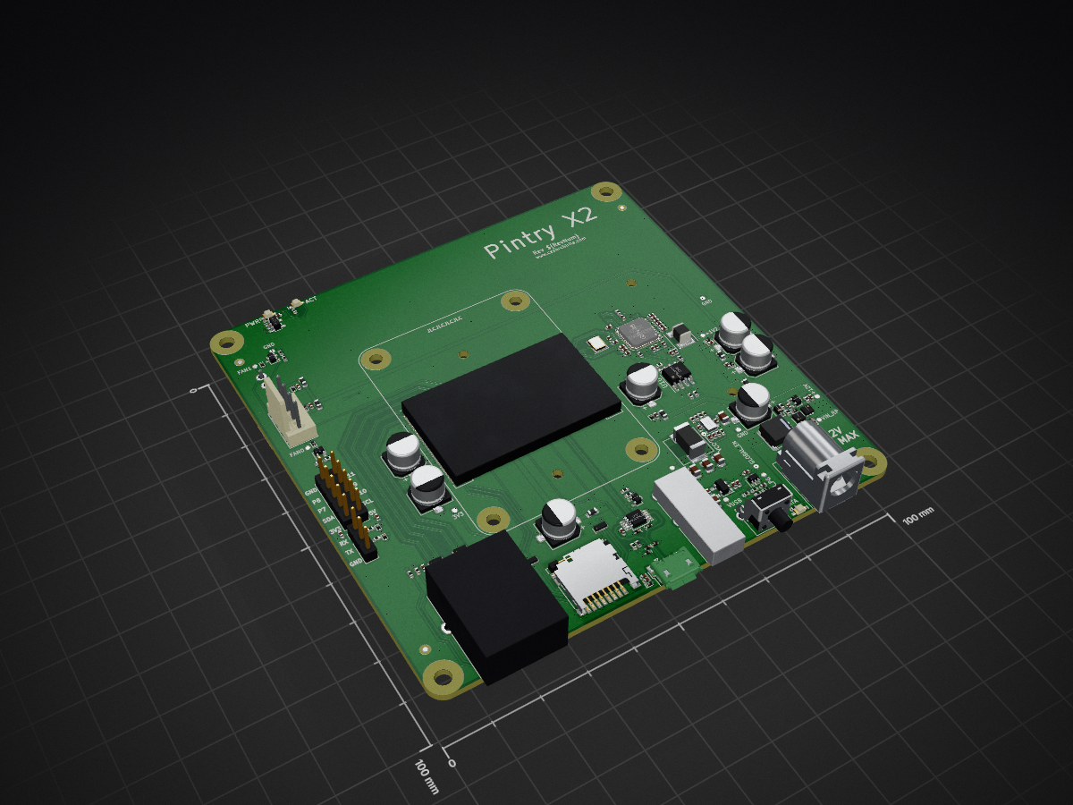
Pintry X2 is an open-source printed circuit board by icamaster, from the icamaster/Pintry repository on GitHub, published under the MIT licence. It is a 4-layer board of 100 × 100 mm with 193 parts on 241 nets, routed with 1,473 tracks and 483 vias.
It is built around the ASM1061, 74AHCT1G126GV and SN74LVC1G17DBV, with the AP62600, DM3D-SF and FSUSB30MUX among its other parts. Its parts include 65 capacitors, 36 resistors, 24 diodes, 13 ICs and 11 connectors. It belongs with the computers and single-board computers boards and the Raspberry Pi (Linux) boards of this library.


The Pintry X2 is a two bay NAS (Network Attached Storage) based on the Raspberry Pi Compute Module 4. It uses the ASMedia AS1061 PCIe to Sata bridge to connect up to 2 drives (3.5'/2.5' HDD or 2.5' SSD) to the SoM running a Linux based OS (Raspberry Pi OS).
Here is a link for additional information: https://www.cezarchirila.com/projects/pintry-x2.html
Pi + Pantry = Pintry
Add these changes at the end of the /boot/config.txt to enable specific functionality:
# Enable FAN control for FAN0
dtoverlay=gpio-fan,gpiopin=12

# Enable FAN control for FAN1
#dtoverlay=gpio-fan,gpiopin=13

# Enable full functionality of On/Off button
dtoverlay=gpio-shutdown,gpio_pin=21,active_low=0,gpio_pull=off

# Enable UART - UNTESTED
#dtoverlay=uart0,txd0_pin=14,rxd0_pin=15,pin_func=4
#enable_uart=1
Remember to remove the '#' in from of options you want to enable.
Previously, to be able to use SATA drives with a CM4 you had to recompile the kernel with added SATA support. See instructions here (credit to Jeff Geerling for instructions). However, newer kernel versions have SATA support built-in, so you should not have to worry about this.
The enclosure supports 2.5' drives only. It does not have any mounting features for fans, but there is room for a 60mm fan on the bottom as shown in the images below. It does not need supports for printing. Designed in Fusion 360.
For assembly, you will need the following:
To keep temperatures under control, I have used a RAM heatsink on the ASM1061 IC and a 60mm fan on the bottom of the enclosure tied to the FAN header and controlled via the 'gpio-fan' overlay. It is mounted in such way that it blows air over both the CM4 and the ASM1061.
The current latest release is V1.1. This version has not been tested or manufactured yet, therefore I would suggest double checking it if you plan on bulding it! All the necessary manufacturing and assembly files are in the 'OutputJob/Version' and 'Enclosure' folders.
| Qty | Value | Footprint | References |
|---|---|---|---|
| 30 | 0.1uF | PintryParts-Footprints:C_0402_1005Metric | C2, C3, C11, C12, C13, C15, C23, C27, C28, C30, C31, C32, C33, C34, C35, C36 +14 |
| 12 | 4K7 | PintryParts-Footprints:R_0402_1005Metric | R2, R5, R7, R8, R11, R16, R17, R18, R21, R27, R28, R32 |
| 10 | 0.01uF | PintryParts-Footprints:C_0402_1005Metric | C19, C20, C45, C46, C47, C48, C51, C52, C53, C54 |
| 9 | 10uF | PintryParts-Footprints:C_0402_1005Metric | C1, C5, C14, C16, C17, C24, C29, C67, C68 |
| 7 | 865080443007 | Capacitor_SMD:CP_Elec_6.3x5.4 | C8, C10, C49, C50, C55, C56, C66 |
| 7 | D3V3M1U259-7 | Diode_SMD:D_SOD-923 | D3, D4, D5, D6, D10, D11, D12 |
| 7 | DF2S6.2FS,L3M | Diode_SMD:D_SOD-923 | D1, D2, D7, D15, D16, D20, D22 |
| 6 | 100k | PintryParts-Footprints:R_0402_1005Metric | R23, R24, R25, R26, R31, R35 |
| 6 | MPZ1608S101ATAH0 | PintryParts-Footprints:L_0603_1608Metric | FB1, FB2, FB3, FB4, FB5, FB6 |
| 6 | TPD4EUSB30 | Package_SON:USON-10_2.5x1.0mm_P0.5mm | U1, U2, U5, U6, U11, U12 |
| 5 | 100K | PintryParts-Footprints:R_0402_1005Metric | R9, R10, R15, R22, R36 |
| 5 | 1K | PintryParts-Footprints:R_0402_1005Metric | R1, R6, R14, R19, R20 |
| 5 | 22uF | PintryParts-Footprints:C_0805_2012Metric | C6, C58, C62, C63, C64 |
| 5 | DF2S16FS,L3M | Diode_SMD:D_SOD-923 | D13, D14, D21, D23, D25 |
| 4 | GND | PintryParts-Footprints:TestPoint_Pad_D1.0mm | TP6, TP15, TP16, TP17 |
| 4 | M3 MountingHole | PintryParts-Footprints:MountingHole_3.2mm_M3 | H1, H2, H3, H4 |
| 3 | APA2107SECK | PintryParts-Footprints:APA2107SECK | D8, D9, D17 |
| 3 | BSS138PW | Package_TO_SOT_SMD:SOT-323_SC-70 | Q1, Q2, Q3 |
| 3 | Fiducial Bottom | Fiducial:Fiducial_1mm_Mask2mm | FID2, FID4, FID6 |
| 3 | Fiducial Top | Fiducial:Fiducial_1mm_Mask2mm | FID1, FID3, FID5 |
| 2 | 0R | PintryParts-Footprints:R_0402_1005Metric | R33, R34 |
| 2 | 12K1 | PintryParts-Footprints:R_0402_1005Metric | R12, R13 |
| 2 | 1735284-3 | PintryParts-Footprints:TE_1735284-3 | J9, J10 |
| 2 | 1uF | PintryParts-Footprints:C_0402_1005Metric | C21, C61 |
| 2 | 470R | PintryParts-Footprints:R_0402_1005Metric | R3, R4 |
| 2 | BZX384-B13 | Diode_SMD:D_SOD-323 | D24, D26 |
| 2 | Fan | Connector_Molex:Molex_KK-254_AE-6410-04A_1x04_P2.54mm_Vertical | J7, J8 |
| 2 | SIA483DJ | PintryParts-Footprints:Vishay_PowerPAK_SC70-6L_Single | Q5, Q7 |
| 1 | +12V | PintryParts-Footprints:TestPoint_Pad_D1.0mm | TP5 |
| 1 | +1V2 | PintryParts-Footprints:TestPoint_Pad_D1.0mm | TP11 |
| 1 | +5V | PintryParts-Footprints:TestPoint_Pad_D1.0mm | TP4 |
| 1 | 15pF | PintryParts-Footprints:C_0402_1005Metric | C18 |
| 1 | 221K | PintryParts-Footprints:R_0402_1005Metric | R29 |
| 1 | 30K1 | PintryParts-Footprints:R_0402_1005Metric | R30 |
| 1 | 3V3 | PintryParts-Footprints:TestPoint_Pad_D1.0mm | TP18 |
| 1 | 54-00131 | PintryParts-Footprints:54-00131 | J11 |
| 1 | 74AHCT1G126 | Package_TO_SOT_SMD:SOT-353_SC-70-5 | U4 |
| 1 | AP62600 | PintryParts-Footprints:V-QFN2030-12 (Type A) | U13 |
| 1 | ASM1061 | PintryParts-Footprints:QFN-48-1EP_7x7mm_P0.5mm_EP4.025x4.025mm | U7 |
| 1 | BC857BW | Package_TO_SOT_SMD:SOT-323_SC-70 | Q6 |
| 1 | ComputeModule4-CM4 | PintryParts-Footprints:Raspberry-Pi-4-Compute-Module | Module1 |
| 1 | DLW5BTM101SQ2L | PintryParts-Footprints:DLW5BTM101SQ2L | FL1 |
| 1 | DM3D-SF | Connector_Card:microSD_HC_Hirose_DM3D-SF | J4 |
| 1 | ECS-200-12-33-AGN-TR | Crystal:Crystal_SMD_3225-4Pin_3.2x2.5mm | Y1 |
| 1 | Expansion | Connector_PinHeader_2.54mm:PinHeader_2x05_P2.54mm_Vertical | J6 |
| 1 | FAN0 | PintryParts-Footprints:TestPoint_Pad_D1.0mm | TP10 |
| 1 | FAN1 | PintryParts-Footprints:TestPoint_Pad_D1.0mm | TP9 |
| 1 | FSUSB30MUX | Package_SO:MSOP-10_3x3mm_P0.5mm | U14 |
| 1 | GLOBAL_EN | PintryParts-Footprints:TestPoint_Pad_D1.0mm | TP8 |
| 1 | JD0-0001NL | PintryParts-Footprints:Pulse-JD0-0001NL-0-0-MFG | J3 |
| 1 | MIC2005-0.5LYM5 | Package_TO_SOT_SMD:SOT-23-5 | U15 |
| 1 | NRS5030T4R7MMGJ | PintryParts-Footprints:L_Taiyo-Yuden_NR-50xx | L1 |
| 1 | PA4341.122NLT | PintryParts-Footprints:Pulse_PA4341 | L2 |
| 1 | RUN_PG | PintryParts-Footprints:TestPoint_Pad_D1.0mm | TP7 |
| 1 | SN74LVC1G17 | Package_TO_SOT_SMD:SOT-23-5 | U3 |
| 1 | SST25VF512A | Package_SO:SOIC-8_3.9x4.9mm_P1.27mm | U10 |
| 1 | SW_Push | Button_Switch_THT:SW_Tactile_SPST_Angled_PTS645Vx58-2LFS | SW1 |
| 1 | TBD | PintryParts-Footprints:C_0402_1005Metric | C59 |
| 1 | UART | Connector_PinHeader_2.54mm:PinHeader_1x03_P2.54mm_Vertical | J5 |
| 1 | USB_A | PintryParts-Footprints:USB_A_Amphenol_ICC_73725-11A0BLF_Horizontal | J2 |
| 1 | USB_B_Micro | PintryParts-Footprints:USB_Micro-B_Amphenol_10103594-0001LF_Horizontal | J1 |
| 1 | VCC | PintryParts-Footprints:TestPoint_Pad_D1.0mm | TP2 |
| 1 | VIN | PintryParts-Footprints:TestPoint_Pad_D1.0mm | TP1 |
| 1 | VIN_RP | PintryParts-Footprints:TestPoint_Pad_D1.0mm | TP3 |
| 1 | VUSB | PintryParts-Footprints:TestPoint_Pad_D1.0mm | TP14 |
It measures 100 × 100 mm and has 4 copper layers, 1.59 mm thick.
193 parts, built around the ASM1061, 74AHCT1G126GV, SN74LVC1G17DBV and AP62600. The full list of its parts is on this page, with links to each part's symbol and footprint where PCBKit's library has them.
From the icamaster/Pintry repository on GitHub, at the commit this page was made from: the board is Pintry-X2/Pintry-X2.kicad_pcb and its schematic Pintry-X2/CM4-A.kicad_sch. PCBKit opens the board in the browser, with nothing to install.
Its repository publishes it under the MIT licence: you may reuse it on that licence's terms (keep the author's notice, and for a copyleft licence share your changes alike).
icamaster/picothermal
Thermal camera based on Flir Lepton with RP2040 and USB-C

will-tm/gbc-cm4-aio
This project is a drop-in replacement board that fits and Gameboy Color shell and use the same IPS display as used in GBC kits.


snhobbs/scopefun-hardware
This repository contains Scopefun hardware schematics and pcb layout files.


mwuerms/lighthouse_hardware
+ lighthouse + buoy: hand sender, ble advertising

LtBrain/MuBook
A x86 carrier board for the LattePanda Mu