4 layers84 × 62 mm
Quad AMBE3000
m1geo/Quad-AMBE3000
A PCB for four DVSI AMBE-3000R Vocoders for use with WebSDRs/Audio transcoding
200 parts19MIT
 jaronbrown/SDR_Receiver_Design1
The microPython module to control the SI5351, si5351.py, was provided by https://github.com/thaaraak/Tinypico-Radio/tree/master.
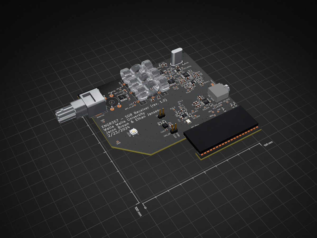
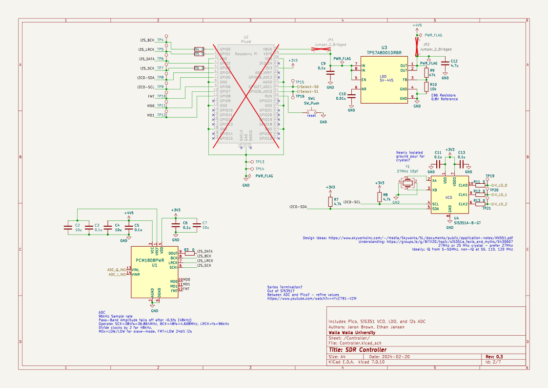
ENGR357-receiverDesign is an open-source printed circuit board by jaronbrown, from the jaronbrown/SDR_Receiver_Design repository on GitHub. It is a 4-layer board of 100 × 100 mm with 132 parts on 101 nets, routed with 718 tracks and 156 vias.
It is built around the ADA4805-2ARMZ, SN74CBT3253D and SI5351A-B-GT, with the TPS7A8001DRBR among its other parts. Its parts include 41 capacitors, 26 resistors, 9 ICs, 9 inductors and 2 diodes. It belongs with the RP2040 boards of this library.


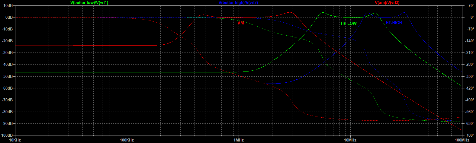
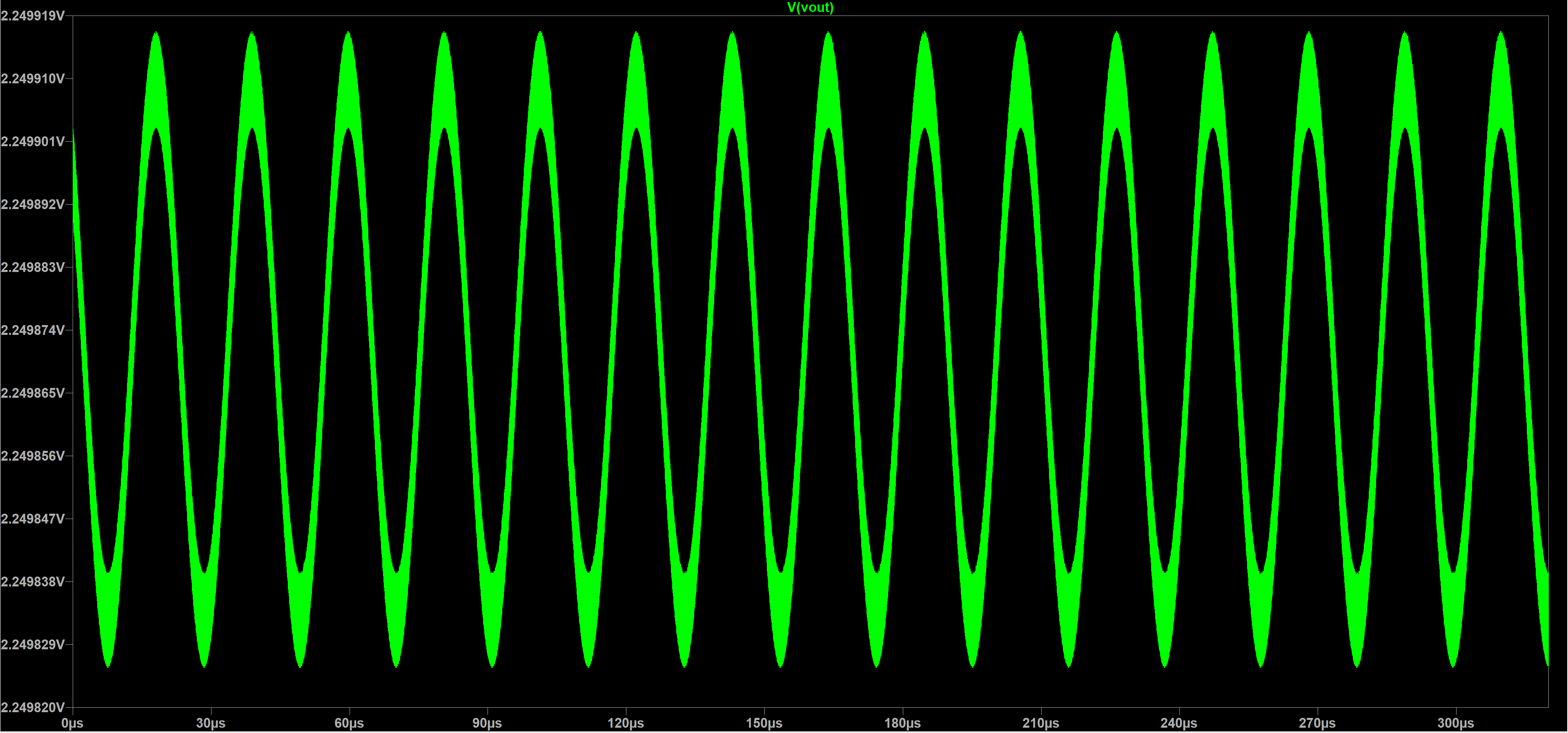
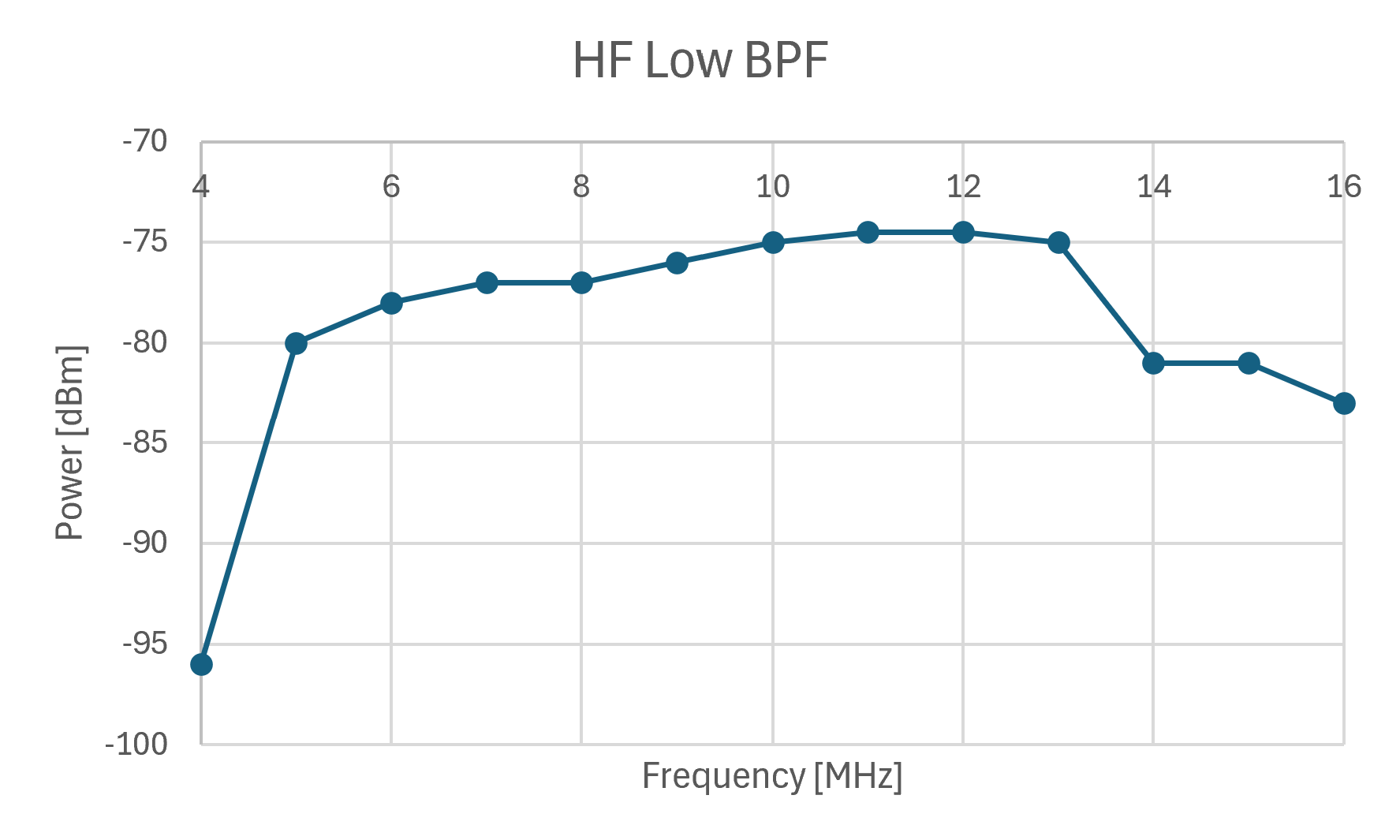
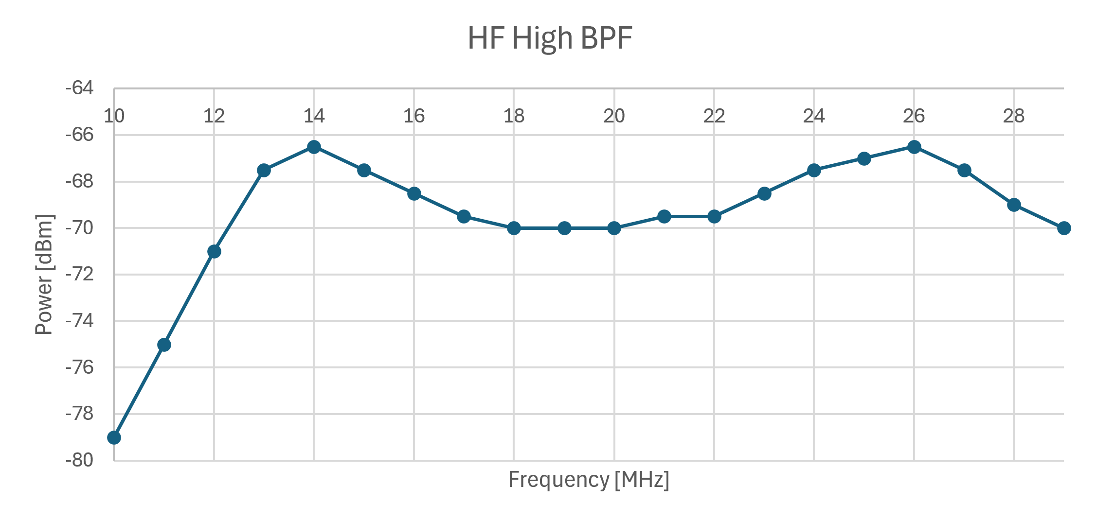
Various core elements of the design were simulated to test their functionality. Notable simulations include a Monte Carlo simulation of the three bandpass filters (frequency response shown below) to determine effects of component tolerances and a simulation of the Tayloe detector, along with its "differential" amplifiers. The Tayloe detector input is a 1 $\mu V$ sinewave and the output (of the I channel) can be seen in the graph below. In the actual implementation, there is a 1 $\mu F$ blocking capacitor before the ADC and audio jack, but this is omitted for sake of simulation. This would remove the 2.25V DC offset.
Bandpass Filters
Tayloe Detector
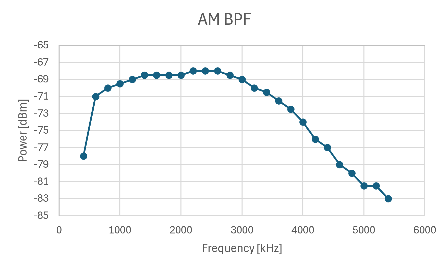
The boards tested were fabricated by JLCPCB. They also installed all the surface-mount components--LCSC part numbers included in schematic. Total fabrication cost (including building the boards) from JLCPCB was about $120 USD for 5 boards. The build plan was followed for assembling the boards and testing their functionality. The specifications for the inductors and transformer used, can be found in Inductors.
The software for the Raspberry Pi Pico W consists of three microPython files: main.py, radio.py, and si5351.py. All three files should be loaded onto the Pico.
The microPython module to control the SI5351, si5351.py, was provided by https://github.com/thaaraak/Tinypico-Radio/tree/master. Some minor changes were made to the outputs_enabled setter in order to allow individual clock enabling/disabling--used for the AM mixer local oscillator.
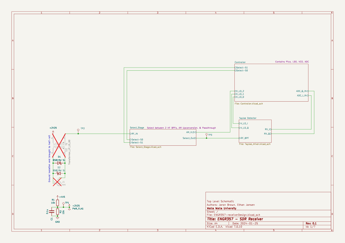
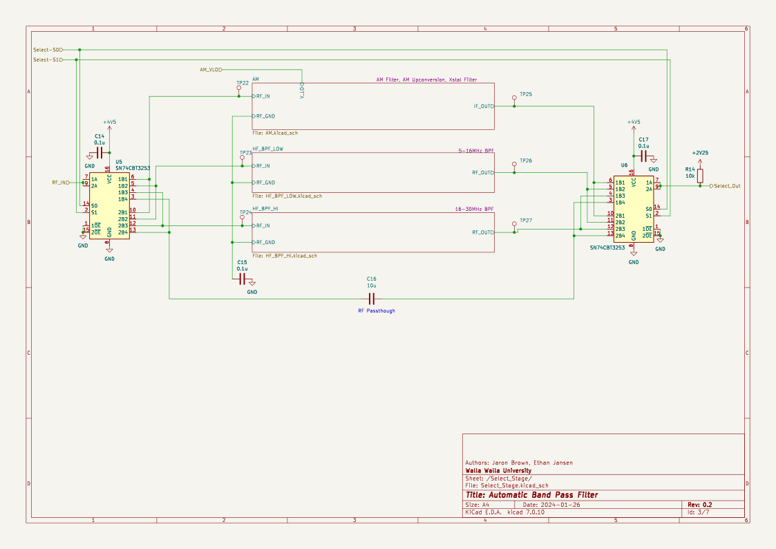
The radio control is handled by radio.py which after initializing a Radio, run() can be used to parse Quisk commands and automatically control bandpass filter selection (based on frequency) and frequency. The bandpass filters can also be controlled manually by entering "BAND,AUTO" to allow for manual testing and use of the built in bypass capacitor. Frequencies from 4-32 MHz are handled via the HF HIGH/LOW BPFs with a single stage of mixing. Frequencies from 0.4-4 MHz are handled via AM mixing (due to the SI5351 not maintaining quadrature below 4 MHz). When switching from AM bands back to HF the SI5351 control is reinitialized to prevent unpredictable clock drift.
Currently there is no support for WiFi control/data transmit, nor is there support for the on-board ADC. This would require migrating to C for DMA. This is coming soon TM.
This SDR is designed to be used with Quisk (https://james.ahlstrom.name/quisk/). Some basic Quisk device configs are provided in quisk. Currently there is no custom widget support for bandpass selection and AM offsets (for tuning away from center).
An optional Dockerfile and sample start script is provided to run Quisk via Docker--though this requires proper /dev/ttyACM0 permissions, pulseaudio, and xserver. If running on Windows via WSL the aforementioned packages should be installed as well as utilizing usbipd-win (https://james.ahlstrom.name/quisk/) to passthrough the Pico connection.
stl files for a 3d printable case are included. Note that because the board does not have any mounting holes the case is a friction fit--consider adjusting tolerances when printing.
Testing revealed the radio functions over the planned 10-30 MHz as well as the AM commercial frequencies (using the second mixer), though some signal overlap is apparent for AM. The bandpass filters were characterized using a signal generator and a spectrum analyzer.
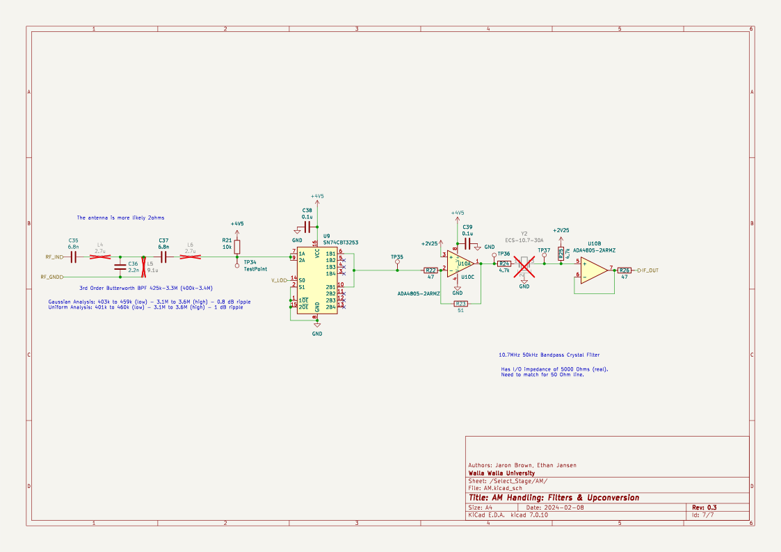
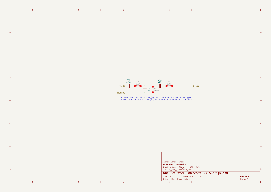
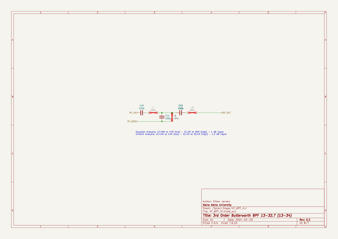
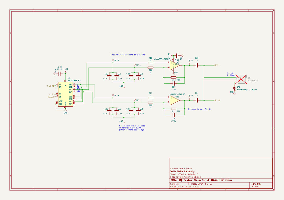
| Qty | Value | Footprint | References |
|---|---|---|---|
| 35 | TestPoint | TestPoint:TestPoint_THTPad_D1.0mm_Drill0.5mm | POST_XSTAL, PRE_XSTAL, TP1, TP2, TP10, TP11, TP12, TP13, TP14, TP15, TP16, TP19, TP20, TP21, TP22, TP23 +19 |
| 14 | 0.1u | Capacitor_SMD:C_0805_2012Metric | C1, C3, C5, C6, C9, C11, C13, C14, C15, C17, C18, C29, C38, C39 |
| 11 | 0 | Resistor_SMD:R_0805_2012Metric | R3, R4, R5, R6, R11, R12, R13, R15, R16, R17, R18 |
| 8 | 4.7n | Capacitor_SMD:C_0603_1608Metric | C19, C20, C21, C22, C23, C24, C25, C26 |
| 5 | 10k | Resistor_SMD:R_0805_2012Metric | R1, R2, R10, R14, R21 |
| 4 | 10u | Capacitor_SMD:C_0805_2012Metric | C2, C4, C7, C16 |
| 4 | 4.7k | Resistor_SMD:R_0805_2012Metric | R7, R8, R24, R25 |
| 4 | SN74CBT3253 | SN74CBT3253CPWR:SOP65P640X120-16N | U5, U6, U7, U9 |
| 3 | 470p | Capacitor_SMD:C_0805_2012Metric | C32, C33, C34 |
| 2 | 150p | Capacitor_SMD:C_0603_1608Metric | C40, C42 |
| 2 | 1u | Capacitor_SMD:C_0805_2012Metric | C30, C31 |
| 2 | 2.7u | Inductor_THT:L_Toroid_Vertical_L10.0mm_W5.0mm_P5.08mm | L4, L6 |
| 2 | 270p | Capacitor_SMD:C_0402_1005Metric | C27, C28 |
| 2 | 390n | Inductor_THT:L_Toroid_Vertical_L10.0mm_W5.0mm_P5.08mm | L7, L9 |
| 2 | 47 | Resistor_SMD:R_0805_2012Metric | R22, R26 |
| 2 | 5.1k | Resistor_SMD:R_0805_2012Metric | R19, R20 |
| 2 | 6.8n | Capacitor_SMD:C_0603_1608Metric | C35, C37 |
| 2 | 620n | Inductor_THT:L_Toroid_Vertical_L10.0mm_W5.0mm_P5.08mm | L1, L3 |
| 2 | ADA4805-2ARMZ | Package_SO:MSOP-8_3x3mm_P0.65mm | U8, U10 |
| 2 | B5819W SL | Diode_SMD:D_SOD-123 | D1, D2 |
| 2 | Jumper_2_Bridged | Connector_PinHeader_2.54mm:PinHeader_1x02_P2.54mm_Vertical | JP1, JP2 |
| 1 | 0.01u | Capacitor_SMD:C_0603_1608Metric | C10 |
| 1 | 180n | Inductor_THT:L_Toroid_Vertical_L10.0mm_W5.0mm_P5.08mm | L8 |
| 1 | 2.2n | Capacitor_SMD:C_0805_2012Metric | C36 |
| 1 | 27Mhz 10pF | Crystal:Crystal_SMD_3225-4Pin_3.2x2.5mm | Y1 |
| 1 | 330p | Capacitor_SMD:C_0603_1608Metric | C41 |
| 1 | 4.7u | Capacitor_SMD:C_0603_1608Metric | C12 |
| 1 | 47k | Resistor_SMD:R_0805_2012Metric | R9 |
| 1 | 51 | Resistor_SMD:R_0805_2012Metric | R23 |
| 1 | 560n | Inductor_THT:L_Toroid_Vertical_L10.0mm_W5.0mm_P5.08mm | L2 |
| 1 | 9.1u | Inductor_THT:L_Toroid_Vertical_L10.0mm_W5.0mm_P5.08mm | L5 |
| 1 | Ant | Connector_Coaxial:BNC_Amphenol_B6252HB-NPP3G-50_Horizontal | J1 |
| 1 | AudioJack3 | Connector_Audio:Jack_3.5mm_CUI_SJ1-3523N_Horizontal | Audio Out |
| 1 | ECS-10.7-30A | Crystal:Crystal_HC49-U-3Pin_Vertical | Y2 |
| 1 | GND_Isolation | Jumper:SolderJumper-2_P1.3mm_Open_RoundedPad1.0x1.5mm | JP3 |
| 1 | PCM1808PWR | PCM1808:PW14 | U1 |
| 1 | PicoW | RPi_Pico:RPi_PicoW_SMD_TH | RPi Pico |
| 1 | SW_Push | Button_Switch_SMD:SW_Push_1P1T_XKB_TS-1187A | SW1 |
| 1 | Si5351A-B-GT | Package_SO:MSOP-10_3x3mm_P0.5mm | U4 |
| 1 | TPS7A8001DRBR | TPS7A8001DRBR:DRB0008A-MFG | U3 |
| 1 | Transformer_1P_1S_00 | Transformer_THT:Transformer_Toroid_Horizontal_D10.5mm_Amidon-T37 | T1 |
m1geo/Quad-AMBE3000
A PCB for four DVSI AMBE-3000R Vocoders for use with WebSDRs/Audio transcoding


Dizzerin/Software-Defined-Radio
Quadrature sampling down converter software defined radio

KonradMcClure/SDR_Receiver
Software Defined Radio Receiver designed together with Caleb Froelich (https://github.com/froeca) for our Walla Walla University Electronics II project.

pricna/Software-Defined-Radio-Receiver
Software Defined Radio receiver created for Engineering Electronics II at Walla Walla University.

gmtii/Prototipo-R820T2
Proyecto 'breakout' de un R820T2 más un QSD para obtener salida IQ directamente a la tarjeta de sonido del PC. La idea es experimentar con el R820T2 y un QSD cuya frecuencia de refencia es 4X a la de demodulación…


JoshuaMularczyk/Software_Defined_Radio_Receiver
This project was taken on with the goal to create a Software Defined Radio (SDR) in coolaboration with my partner Christian Williams.
It measures 100 × 100 mm and has 4 copper layers, 1.61 mm thick.
132 parts, built around the ADA4805-2ARMZ, SN74CBT3253D, SI5351A-B-GT and TPS7A8001DRBR. The full list of its parts is on this page, with links to each part's symbol and footprint where PCBKit's library has them.
From the jaronbrown/SDR_Receiver_Design repository on GitHub, at the commit this page was made from: the board is kicad/ENGR357-receiverDesign.kicad_pcb and its schematic kicad/AM.kicad_sch. PCBKit opens the board in the browser, with nothing to install.
Its repository states no licence, so its author keeps all rights: ask jaronbrown before reusing the design.