2 layers69.9 × 99.1 mm
Complete Schematic V6
JoshuaMularczyk/Software_Defined_Radio_Receiver
This project was taken on with the goal to create a Software Defined Radio (SDR) in coolaboration with my partner Christian Williams.
58 parts1MIT
 JoshuaMularczyk/Software_Defined_Radio_Receiver1
This project was taken on with the goal to create a Software Defined Radio (SDR) in coolaboration with my partner Christian Williams.
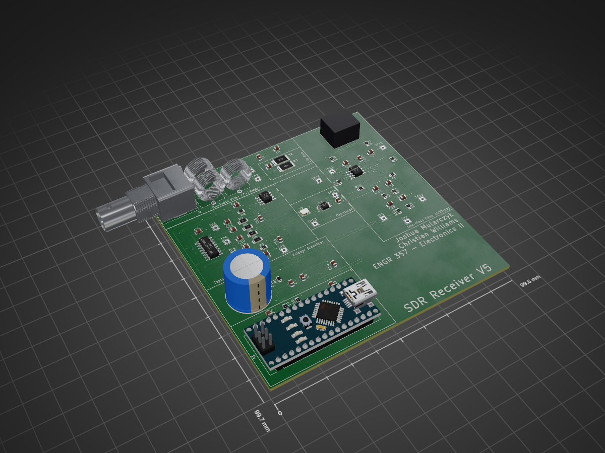
Complete Schematic V5 is an open-source printed circuit board by JoshuaMularczyk, from the JoshuaMularczyk/Software_Defined_Radio_Receiver repository on GitHub, published under the MIT licence. It is a 2-layer board of 99.6 × 99.7 mm with 74 parts on 62 nets, routed with 747 tracks and 153 vias.
It is built around the LM4562MA, LT6231 and SN74CBT3253D, with the SI5351A-B-GT and SJ1-3525N among its other parts. Its parts include 27 capacitors, 21 resistors, 4 ICs, 3 inductors and 2 connectors. It belongs with the AVR (ATmega, ATtiny) boards of this library.


This project was taken on with the goal to create a Software Defined Radio (SDR) in coolaboration with my partner Christian Williams. This project was completed for my Engineering Electronics II class and given to us by our professor, Dr. Rob Frohne.
These are the design specifications and objectives that my partner and I decided on. Origianlly, we decided to build a commercial FM radio, but after discusstion with Dr. Frohne, we reconsidered. The final specifications we decided on are as follows:
Our (SDR) receiver connects to an antenna (mounted ontop of the Engineering Building) and covers the filtering, mixing, and amplifying of the desired I and Q signals. Our I and Q signals are then passed through an external sound card and software handles the demodulation of the signal into audio. The mixing in our SDR is handled using an Arduino Nano running code provided to us by Dr. Rob Frohne which can be found in the Arduino file. The Arduino interfaces with Quisk, an SDR that controls our receiver through the Arduino. Using Quisk, the radio can be tuned to a certain frequency by adjusting the speed of the local oscillator used in the mixing process.

The block diagram above shows the basic components of our SDR Receiver. The signal is received by an antenna and is passed through the bandpass filter which attenuates signals that are above or below our frequency range of 7-18 MHz. These signals are then passed through the Tayloe Quadrature Product Detector. This generates the I and Q signals for demodulation. Once the signals have been split they pass through the low noise filter which cuts off anything above 100 KHz, creating a smooth output signal. This signal is then send into an external soundcard which demodulates teh signal before it is read by Quisk software. Quisk interfaces to the Arduino Nana and allows for tuning of the desired frequency.

Christian and I built and tested our SDR based on the 5th Rev of this project. These schematics can be found in the Rev 5 file. The follow schematics are our most updated designs. These were created after finding multiple errors while constructing our pcb. The Rev 6 schematics can be downloaded here. These schematics were all designed in KiCad and will be broken down into seperate pieces below.
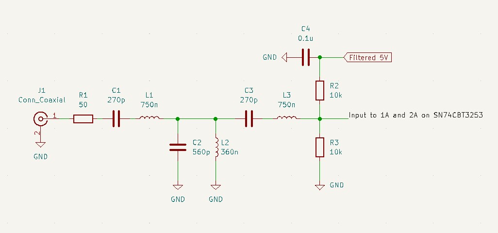
We built this bandpass filter using the LC Filter Design Tool. This is a 3rd-Order Conventional, Series First, Butterworth Filter that will only allow frequencies between 7MHz and 18MHz to pass through it. It has input and output impedances of 50 ohms.

The mixer that Christian and I decided to use was Tayloe Mixer we referenced this paper by Dan Tayloe when designing our mixer. The demultiplexer that we used was the SN74CBT which converts the RF signal into four baseband signals. The Tayloe mixer uses switches to combine the signals that are 180 degrees out of phase with differential amplifiers so that signals above and below the oscilator frequecy can be detected.
Our Lowpass filter was designed using the TI Filter Design Tool [blocked]. It was made using two LT6231 low noise op amps and is designed to block all frequencies greater that 100kHz.
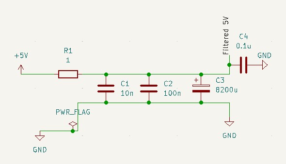
Our Voltage Smoother with take the 5V Vcc and remove as much noise as possible using a very large capacitace. Our schematic here shows the C3 having a value of 8200uF, however we ended up using a 1F capacitor that we already had in the lab. This takes the voltage that comes in from the computer and outputs a smoother 5V for the SDR to use.

Our Si5351 programmable oscillator allows us to input two clock signals that are 90 degrees out of phase into S0 and S1 of the SN74CBT3253. The Arduino Nano controls the frequency that is put out by the Si5351 for tuning. For our testing we had the Aduino set the frequency to 14,190,000 Hz to match what was being output by a signal generator.
We conducted all of our simulations on LTSpice. My partner, Christian Williams, conducted the simulations of both filters and the Tayloe Mixer.
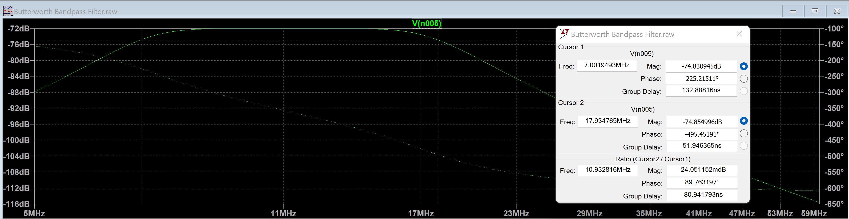

Our Bandpass Filter was designed to allow a frequency range of 7-18MHz to pass through. As seen in the simulation above, curser 1 and cursor 2 mark the two freqency cutoff points. Inbetween them is the peak of our curve which is just where we want it.
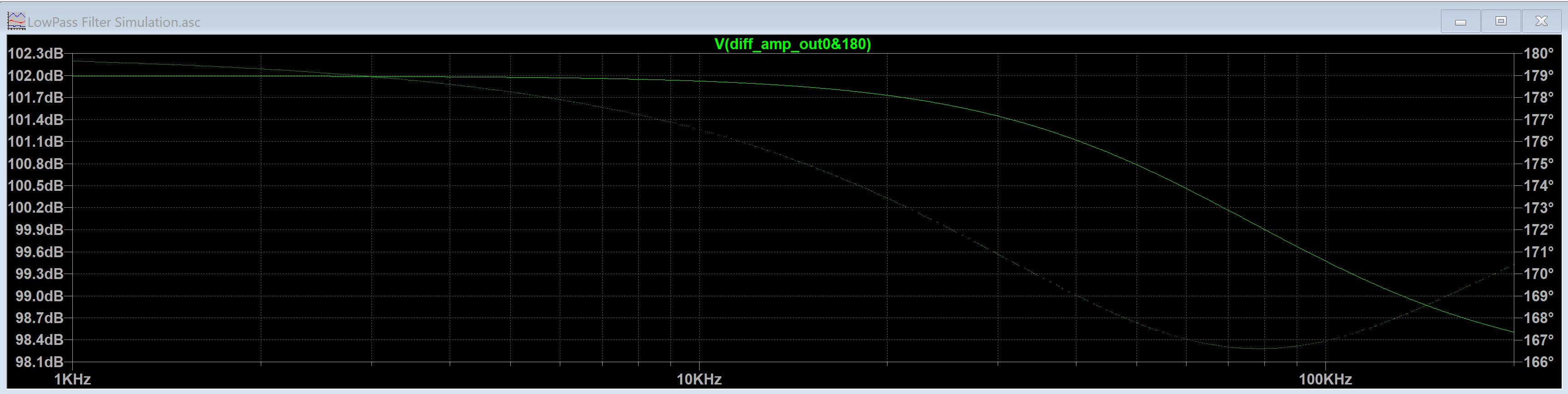
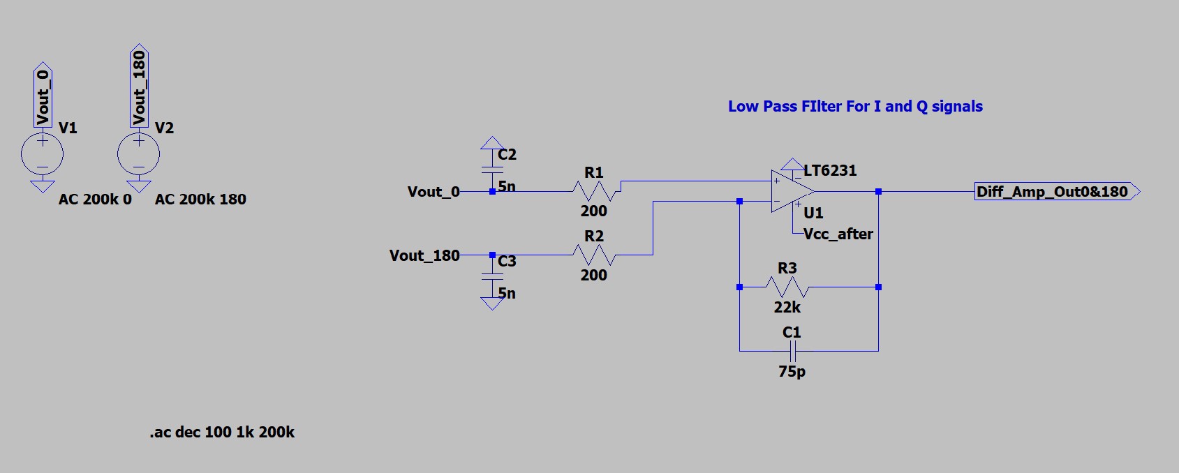
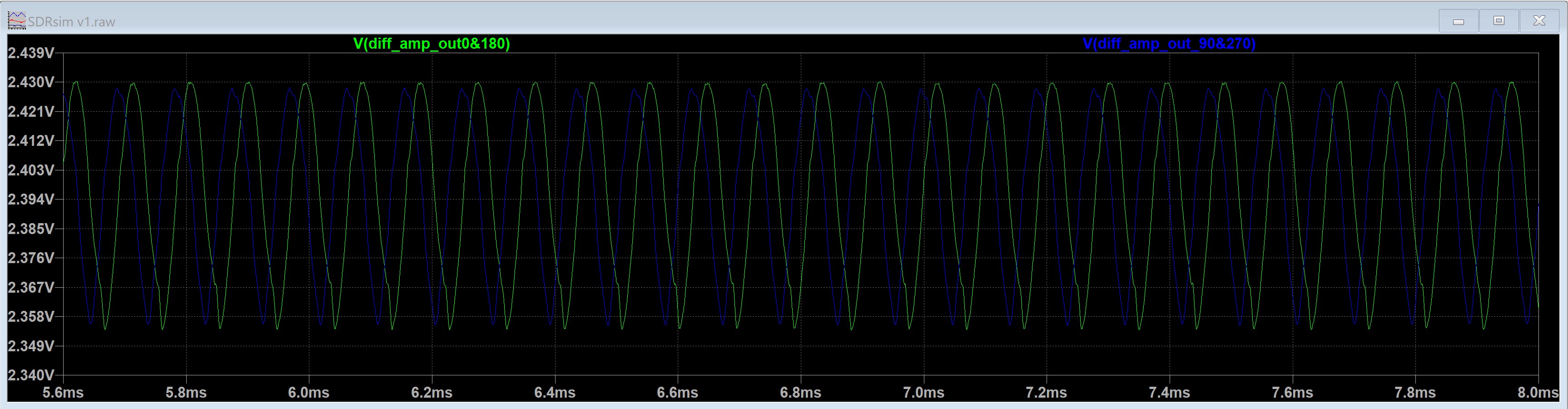

We designed the tayloe mixer using four voltage controlled switches, and four voltage pulses that control them. For our op amps, we added our LT6231, these are already Linear Technology componenets so they dont take long to simulate in LTSpice. The LT6231's had a much lower noise profile than the LM4578's we selected for our second LPF(which we ended up removing in Rev 6), so we knew that the first LPF would take care of mostly everything and the second would just perfect the output. In the simulation window above you can see the baseband signals and the I and Q outputs. They're exactly as expected, about 90 degrees out of phase.

When constructing our Rev 5 board, I ran into three issues. These issues have been fixed and closed. They are explained in detail in the issues page here!
Luckily I was able to fix all of these mistakes with simple cutting and jumping techniques. We immediately fixed the schematics and Christian created Rev 6 of the PCB which was displayed above.
We first tested to see the minimum discernible signal by hooking our board up to a signal generator, our system running quisk software, and a soundcard. We adjusted the attenuator on the signal generator to output a signal of 14.19 MHz and then dropped the signal on the attenuator to see how small of a signal we could detect. In the image below, we see our radio has a minimum disernable signal of inbetween 0.3-0.4 uV!

We then hooked up our SDR to a BNC connector that ran to the roof of our Engineering building into an antenna. The final test was to see if we could hear any radio opperators transmitting around the world. We first looked at the signals being read in to see that our radio was picking up signals as far as Russia and Italy. Next we decided to listen in and found several bandwidths being used for communications. Here are two that we took snippets of.
The first signal that we tuned into was being used to communicate the weather from what sounded like an air traffic control tower.
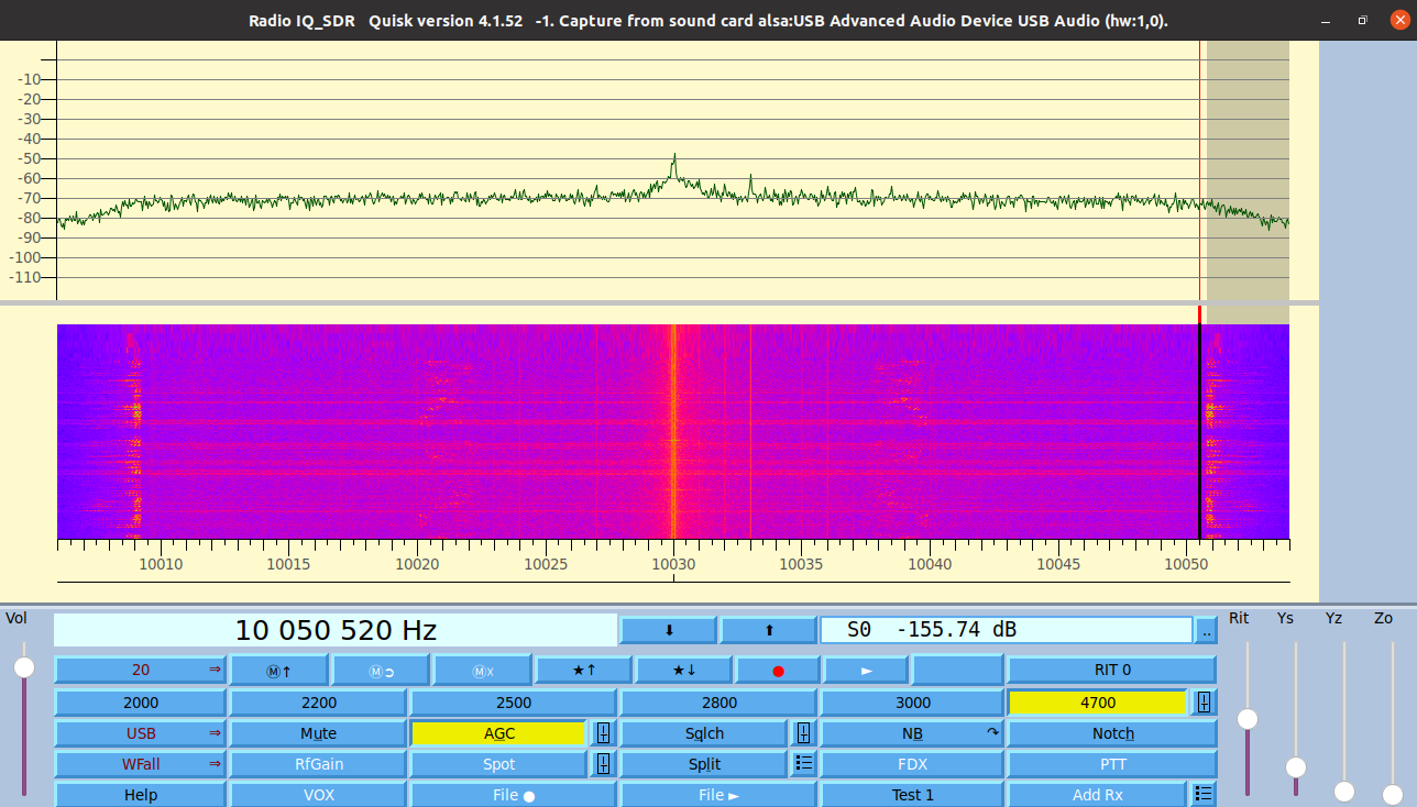
The second was an automated message that would read off the Coordinated Universal time every minute.

We were also able to listen to a few different music stations as well as two men in Hawaii talk about hurricanes to each other.
| Qty | Value | Footprint | References |
|---|---|---|---|
| 15 | TestPoint | TestPoint:TestPoint_THTPad_2.0x2.0mm_Drill1.0mm | TP1, TP2, TP3, TP4, TP5, TP6, TP7, TP8, TP9, TP10, TP11, TP12, TP13, TP14, TP15 |
| 9 | 0.1u | Capacitor_SMD:C_0805_2012Metric | C3, C5, C6, C14, C15, C18, C21, C24, C25 |
| 4 | 100p | Capacitor_SMD:C_0805_2012Metric | C19, C20, C22, C23 |
| 4 | 200 | Resistor_SMD:R_1206_3216Metric | R4, R5, R6, R7 |
| 4 | 5n | Capacitor_SMD:C_0805_2012Metric | C9, C10, C11, C12 |
| 2 | 100 | Resistor_SMD:R_0805_2012Metric | R20, R21 |
| 2 | 10k | Resistor_SMD:R_2512_6332Metric | R2, R3 |
| 2 | 10u | Capacitor_SMD:C_0805_2012Metric | C26, C27 |
| 2 | 17.4k | Resistor_SMD:R_0805_2012Metric | R16, R17 |
| 2 | 2.49k | Resistor_SMD:R_0805_2012Metric | R14, R15 |
| 2 | 22k | Resistor_SMD:R_0805_2012Metric | R8, R9 |
| 2 | 270p | Capacitor_SMD:C_0805_2012Metric | C1, C4 |
| 2 | 4.64k | Resistor_SMD:R_0805_2012Metric | R10, R11 |
| 2 | 4.7k | Resistor_SMD:R_0805_2012Metric | R18, R19 |
| 2 | 52.3k | Resistor_SMD:R_0805_2012Metric | R12, R13 |
| 2 | 750n | Inductor_THT:L_Toroid_Vertical_L10.0mm_W5.0mm_P5.08mm | L1, L3 |
| 2 | 75p | Capacitor_SMD:C_0805_2012Metric | C16, C17 |
| 1 | 1 | Resistor_SMD:R_0805_2012Metric | R1 |
| 1 | 100n | Capacitor_SMD:C_0805_2012Metric | C8 |
| 1 | 10n | Capacitor_SMD:C_0805_2012Metric | C7 |
| 1 | 360n | Inductor_THT:L_Toroid_Vertical_L10.0mm_W5.0mm_P5.08mm | L2 |
| 1 | 560p | Capacitor_SMD:C_0805_2012Metric | C2 |
| 1 | 8200u | Capacitor_THT:CP_Radial_D16.0mm_P7.50mm | C13 |
| 1 | Arduino_Nano_v3.x | Module:Arduino_Nano | A1 |
| 1 | Conn_Coaxial | Connector_Coaxial:BNC_Amphenol_B6252HB-NPP3G-50_Horizontal | J1 |
| 1 | Crystal_GND24_Small | Crystal:Crystal_SMD_3225-4Pin_3.2x2.5mm | Y1 |
| 1 | LM4562MA | Package_SO:SOIC-8_3.9x4.9mm_P1.27mm | U4 |
| 1 | LT6231 | Package_SO:SOIC-8_3.9x4.9mm_P1.27mm | U3 |
| 1 | SJ1-3525N | CUI_SJ1-3225N:CUI_SJ1-3525N | J2 |
| 1 | SN74CBT3253 | Package_SO:SOIC-16_3.9x9.9mm_P1.27mm | U2 |
| 1 | Si5351A-B-GT | Package_SO:MSOP-10_3x3mm_P0.5mm | U1 |
JoshuaMularczyk/Software_Defined_Radio_Receiver
This project was taken on with the goal to create a Software Defined Radio (SDR) in coolaboration with my partner Christian Williams.


greenjacketgirl/SDR_Receiver
This project is an attempt at designing and building a Software Defined Radio receiver that has the capabilities of listening to frequencies ranging from 500kHz to 50MHz utlizing the board designed, a sound card, and…

Dizzerin/Software-Defined-Radio
Quadrature sampling down converter software defined radio

KonradMcClure/SDR_Receiver
Software Defined Radio Receiver designed together with Caleb Froelich (https://github.com/froeca) for our Walla Walla University Electronics II project.

pricna/Software-Defined-Radio-Receiver
Software Defined Radio receiver created for Engineering Electronics II at Walla Walla University.

gmtii/Prototipo-R820T2
Proyecto 'breakout' de un R820T2 más un QSD para obtener salida IQ directamente a la tarjeta de sonido del PC. La idea es experimentar con el R820T2 y un QSD cuya frecuencia de refencia es 4X a la de demodulación…


jaronbrown/SDR_Receiver_Design
The microPython module to control the SI5351, si5351.py, was provided by https://github.com/thaaraak/Tinypico-Radio/tree/master.
It measures 99.6 × 99.7 mm and has 2 copper layers, 1.6 mm thick.
74 parts, built around the LM4562MA, LT6231, SN74CBT3253D and SI5351A-B-GT. The full list of its parts is on this page, with links to each part's symbol and footprint where PCBKit's library has them.
From the JoshuaMularczyk/Software_Defined_Radio_Receiver repository on GitHub, at the commit this page was made from: the board is Schematics/SDRrecV5/Complete Schematic V5.kicad_pcb and its schematic Schematics/Circuit Segment Schematics/Arduino and Si5354.kicad_sch. PCBKit opens the board in the browser, with nothing to install.
Its repository publishes it under the MIT licence: you may reuse it on that licence's terms (keep the author's notice, and for a copyleft licence share your changes alike).