
2 layers100 × 100 mm
SDRBackup2
KonradMcClure/SDR_Receiver
Software Defined Radio Receiver designed together with Caleb Froelich (https://github.com/froeca) for our Walla Walla University Electronics II project.
76 parts7

 KonradMcClure/SDR_Receiver7
Software Defined Radio Receiver designed together with Caleb Froelich (https://github.com/froeca) for our Walla Walla University Electronics II project.
SDRReciever is an open-source printed circuit board by KonradMcClure, from the KonradMcClure/SDR_Receiver repository on GitHub. It is a 2-layer board of 100 × 100 mm with 78 parts on 73 nets, routed with 374 tracks and 12 vias.
It is built around the INA821ID, OP213FPZ and 74AC74M, with the SN74CBT3253D, SI5351A-B-GT and PN2222A among its other parts. Its parts include 24 capacitors, 19 connectors, 17 resistors, 6 ICs and 3 inductors. It belongs with the audio and music boards and the AVR (ATmega, ATtiny) boards of this library.


The goal of this project was to design a low-cost software-defined radio (SDR) receiver. This project was done for my Walla Walla University Electronics II course with my partner Caleb Froelich.
Our professor, Dr. Rob Frohne, gave us the following design objectives:
My partner, Caleb, and I set our own design objectives as well to help narrow down the design we settled on:
The Software Defined Radio (SDR) receiver connects to an antenna and covers the filtering, mixing, and amplification of the desired signal. It then connects a sound card within a computer and software handles the demodulation of the signal into playable audio. The mixing is handled using an Arduino Nano running code provided to us by our Professor, Dr. Rob Frohne, which interfaces with Quisk, an SDR that controls the receiver through the Arduino. Using Quisk, the radio can be tuned to a certain frequency by adjusting the speed of the local oscillator used in the mixing process. Our budget on this project to keep with the low-cost aspect was about $30 including fabrication of the PCB and the required components.
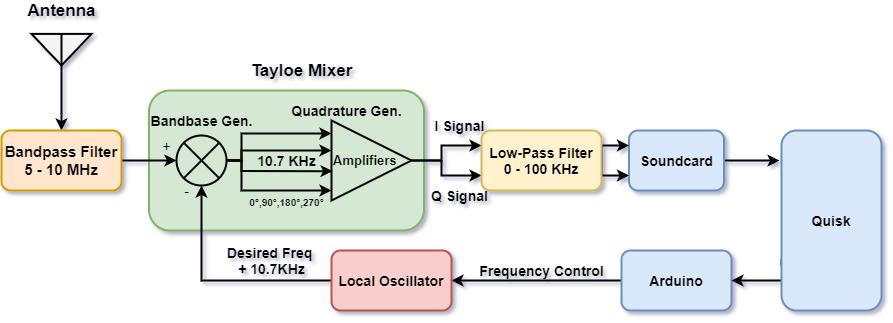 The basics of the SDR Receiver are shown above in the block diagram, with the blue components being defined by software. An antenna picks up the radio signal and passes it through a bandpass filter. This filter will attenuate any signals outside our desired range of 5 – 10 MHz. This is then passed through a Tayloe Mixer, also known as the Tayloe Quadrature Product Detector. The Tayloe Mixer is a simple and efficient mixer that uses a 1:4 demultiplexer and operational amplifiers to generate the I and Q quadrature signals for demodulation. After the signal has been split into four bandbase signals, they are amplified and combined into the I and Q quadrature signals. Those signals go through a final Low-Pass filter that will attenuate signals above 100KHz in frequency, effectively smoothing the output signal. This signal is then sent via 3.5mm audio cable to the soundcard which demodulates the signal. Quisk can then read the input from the sound card and play it. Quisk also interfaces to the Arduino Nano to set the speed of the local oscillator for tuning into the desired frequency.
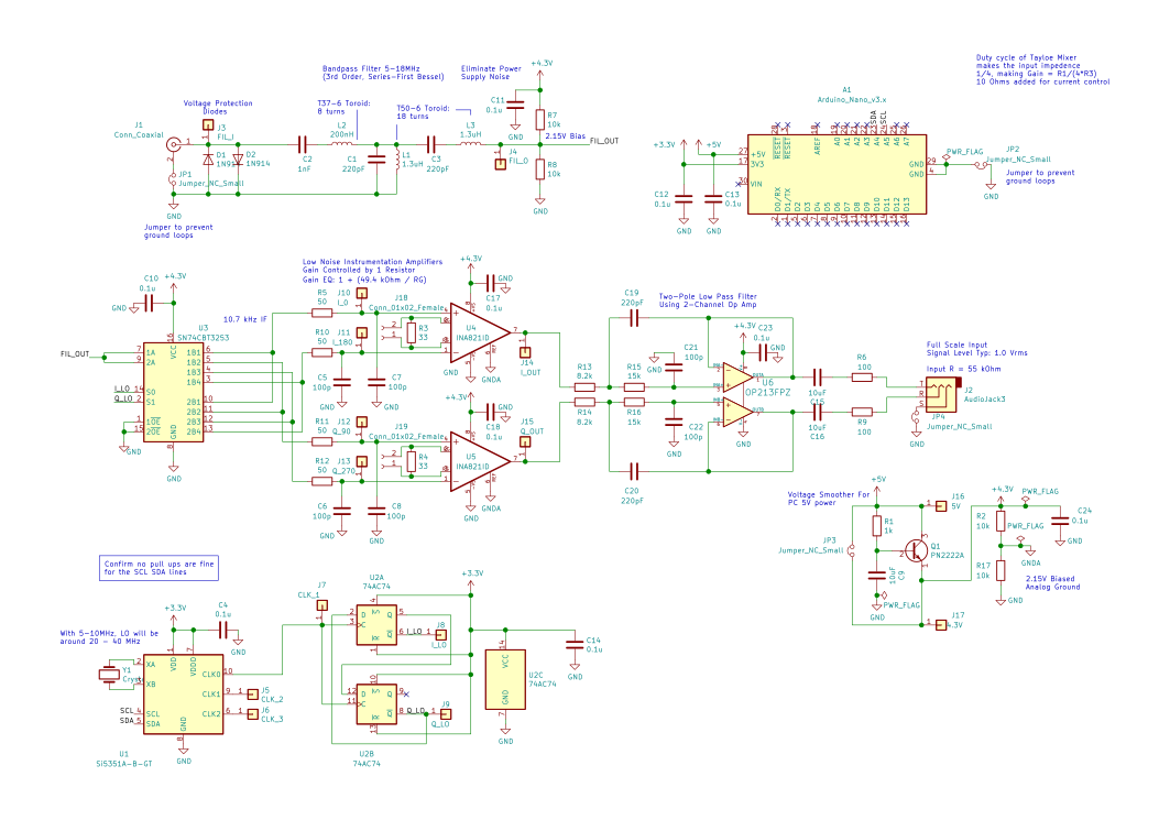
Here is the full design schematic, which we'll break down piece by piece below. You can look at the full image here or download the KiCad project here to take a closer look yourself.
This page is also acting as a report of the design we had for our class project. If the design is continued on in the future, I will likely move this description to the Wiki and update it with the new one.
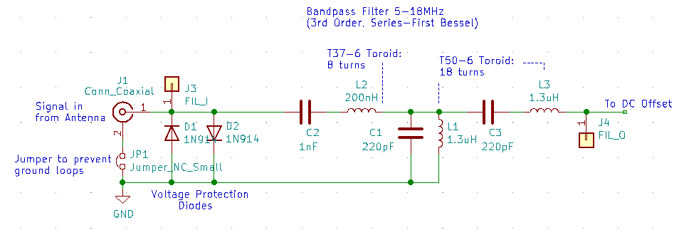
The bandpass filter is a 3rd-Order, Series-First, Bessel filter that was generated using the RF Tools LC Filters Design Tool. It is designed to have input and output impedances of 50 Ω. The motivation to use a series-first configuration came from the capacitor C2 acting as a blockade for any DC signal coming in through the antenna. This would allow us better control over the DC voltage offset that is later required for our single-supply op-amps.
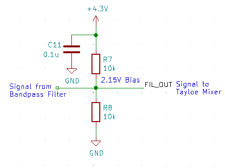
Since we didn't want to create a negative supply for our op-amps, we opted for using them with a single supply and giving our signal a DC offset that sits in the middle between the 4.3V supply and ground. This offset was done via a simple voltage divider of two 10k resistors from 4.3V to GND.
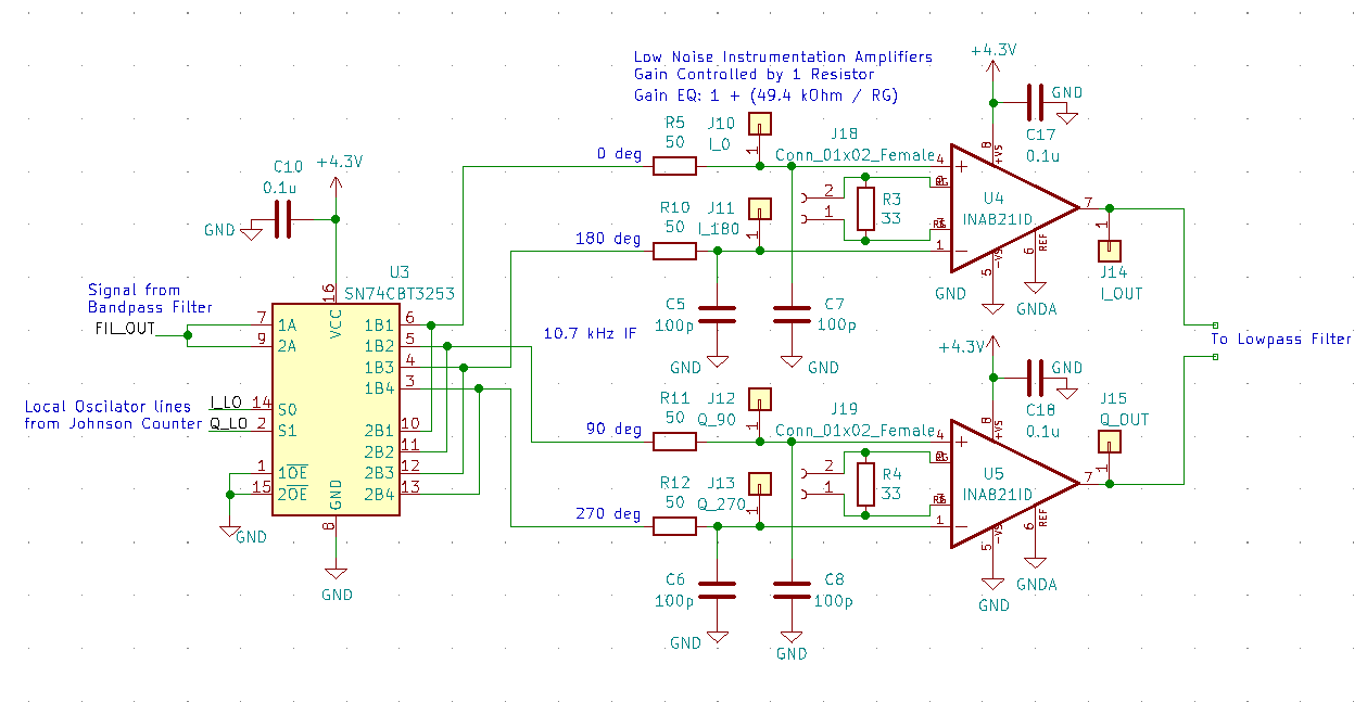
The Tayloe Mixer is a mixer design as seen in this paper by Dan Tayloe. We chose it due to its relatively simple and elegant design. It utilizes a two-channel SN74CBT multiplexer and a pair of INA821ID single gain resistor instrumentation amplifiers. To be more specific, Tayloe describes this as a "switching integrator," rather than a mixer, since a mixer normally produces both a sum and difference frequency of the RF and LO signals, while this design only produces the difference frequency. Acknowledging this, I am going to refer to it as a mixer for simplicity.
The SN74CBT multiplexer acts as a product detector, converting the RF signal into four baseband signals. The switching speed of the MUX is set by the local oscillator, which is a divide by 4 circuit created from a 2-bit Johnson counter seen below. This speed is set to be the RF frequency + 10.7kHz. The sampling capacitors shown between the MUX and instrumentation amps will follow the voltage level of the signal while its line's switch is active, and then hold that value while the switch is closed. This will occur on four different lines, outputting four bandbase signals at phases of 0°, 90°, 180°, and 270°.
The INA821ID Instrumentation Amplifiers act as differential summers of the 0° and 180° signals, and the 90° and 270° signals. This is because the information between the two signals within the two pairs are redundant to each other. Summing 0° and 180° will get us our In-Phase (I) signal and summing the 90° and 270° signals will get us our Quadrature (Q) signal.
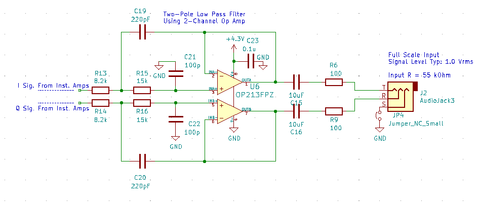
Now that we have our I and Q signals, we'll send them through a Lowpass filter that will attenuate the high frequencies that may still remain in the signal, effectively smoothing it out. For this we used an OP213FPZ op amp, which has 2-channel produces low noise. We used the Texas Instruments Filter Design Tool to generate this as a two-pole filter with a 100kHz cutoff and no gain.
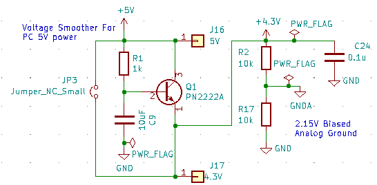
Professor Rob Frohne suggested that we all use a BJT to smooth the voltage coming from the computer, since all the rapid switching that happens in computers tends to create a lot of noise. He measured the output voltage to be about 4.3V based on the design on his GitHub , so we followed his example and designed ours the same way.
We simulated each of our main parts in LTspice to confirm our design. Some things,
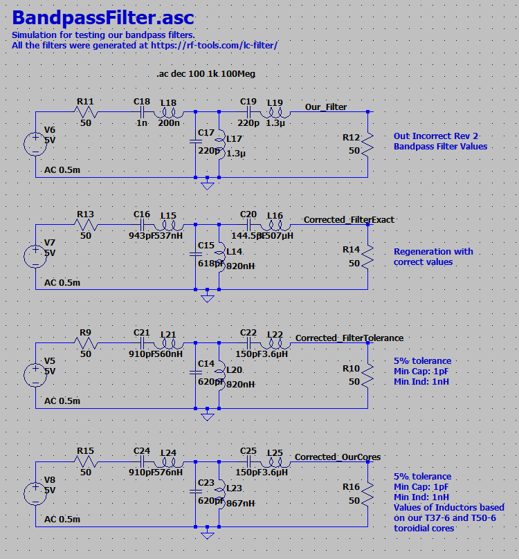
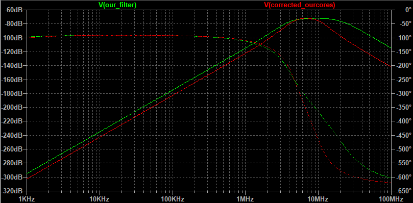
First we simulated the bandpass filter to check it's response. As seen here, and as mentioned later, our bandpass filter for Rev 2 got it's values messed up, which led to a similar, but incorrect response. We re-ran the RF Tools filter design and retested the response of our new filter in LTspice. As can be seen above, the response is much better. The filter on the bottom is calculated with 5% tolerances on all the components and then adjusted for the same toroids that we were provided by our professor. The differences between the bottom three are neglible, so only our current filter and the final adjusted one is plotted.
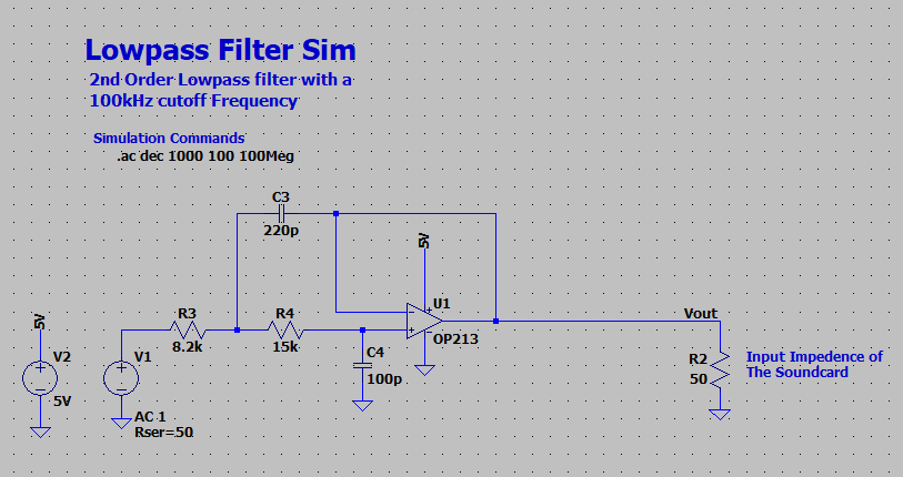
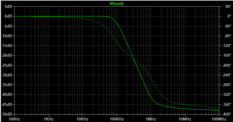
We also tested out our lowpass filter. Luckily LTspice had the OP213's built-in, so we were confident in the results. We can see that the cutoff is at 100kHz as we expected.
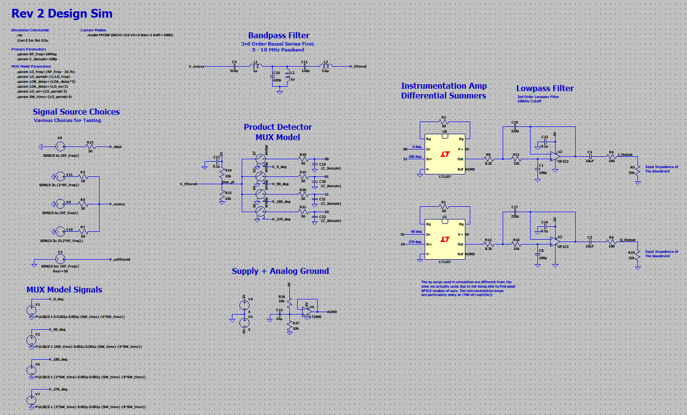
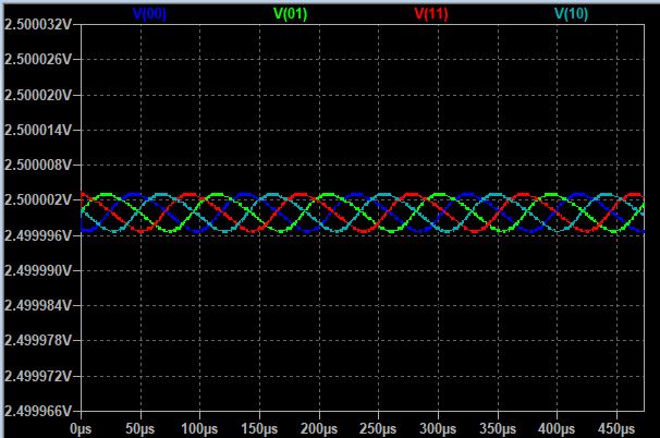
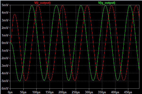
With the two filters out of the way, we can assemble the components inbetween. We have created a model for the mux using four voltage controlled switches, and four voltage pulses that control them in the same manner that the Johnson counter will. For instrumentation amps, we used LT1167s because they didn't take as long to simulate as long as ones we tried to import. The LT1167's had a much higher noise profile than the INA821's we selected, so we figured if we could get these to work, the INA821's would work great. below you can see the baseband signals and the I and Q outputs. They're exactly as we'd like to see them, about 90 degrees out of phase and at a frequency of about 10.8kHz.
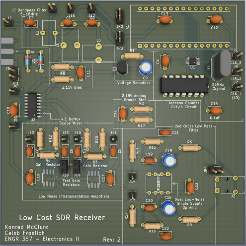
We sourced our board from JLCPCB, who had an offer going of 5, 2-layer, 100x100mm boards for $2. With that size in mind, my partner and I both did our own board layouts and compared after to decide which to send in for printing. We wanted to be sure to match the impedance of the antenna all the way through to the instrumentation amps, so we used the PCB Calculator in KiCad to find the trace width we needed: 1.064mm. The input to the calculator can be seen here:
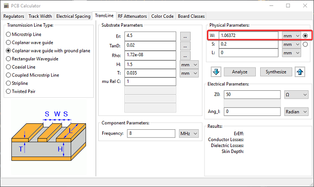
We got the rest of the information, such as the substrate parameters, from JLCPCB's Capabilities page. The design shown above was mine, doing my best to keep traces relatively short and straight and parts close to the next. However...
The PCB layout we decided to print was my partner's who had a layout with really nice divisions between sections, which we believed would be easier for testing. You can find that layout on his GitHub page. All of the components are exactly the same, only the layout is different.
Before receiving the parts from Dr. Frohne, JLCPCB, and Digikey, we put together a Construction and Testing plan which can be found in the documents folder of this repository. This plan wasn't followed exactly to the T during our assembly, but it was an important step for us thinking through the process and how to best assemble the sections so that we could test them in isolation before connecting them together.
For info on the testing of the project, head over to the Testing page on the Wiki!
Loading the Arduino Nano with the OpenRadio software found here, I opened the quisk_conf_openradio.py file and change the info in the SERIAL PORT SETTINGS sections to the COM# port that my Arduino is plugged into. This was found in Device Manager on Windows 10. In Device Manager, I also right clicked the COM port and went to Properties > Port Settings and changed the Bits per second to 57600 to match the value in the config file.
After opening Quisk, I went to Config > Radios and added a radio of the type SoftRock Fixed and named it MyRadioBoy (not necessary), setting it to open to that new radio. Under the new MyRadioBoy tab and Hardware subtab, I changed the Hardware File Path to point to the quisk_conf_openradio.py in the repository. Then in the Sound subtab, I made sure the I/Q Rx Sample Input was set to the sound card input that my 3.5mm cable was connected to from the board.
Sending in a 8MHz test frequency, I could see that the image rejection was pretty good, but I went to the Config tab and clicked the "Adjust receive amplitude and phase" button. I adjusted the levels for the best image rejection I could get, dropping the image down to about the same level as the spurious signals.
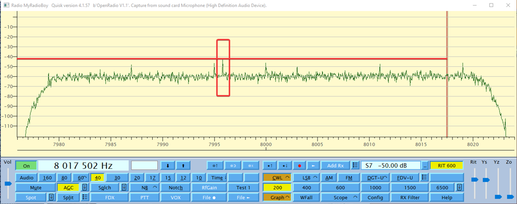 Then, using a step attenuator Caleb and I designed before this radio, I input a 50uV 8MHz signal to the receiver and attenuated it by 40dB, which was just higher than the spurious signals. From this I concluded our minimum discernable signal was about 0.5uV.
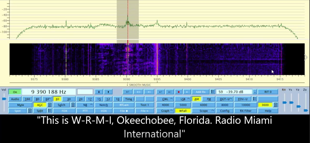 After stringing a wire out to my roof as an antenna (about 50ft up or so) and soldering one end to an SMA connector, I connected it to the board. While not the clearest, it picks up signals pretty well! You can see some signals that I was able to receive here!
My teammate Caleb Froelich, who has his own repository of this project.
My professor Dr. Rob Frohne, who provided us with an example of a similar project of his own here!
| Qty | Value | Footprint | References |
|---|---|---|---|
| 10 | 0.1u | Capacitor_THT:C_Disc_D5.1mm_W3.2mm_P5.00mm | C4, C10, C11, C12, C13, C14, C17, C18, C23, C24 |
| 6 | 100p | Capacitor_THT:C_Disc_D5.0mm_W2.5mm_P2.50mm | C5, C6, C7, C8, C21, C22 |
| 4 | 10k | Resistor_THT:R_Axial_DIN0207_L6.3mm_D2.5mm_P7.62mm_Horizontal | R2, R7, R8, R17 |
| 4 | 50 | Resistor_THT:R_Axial_DIN0207_L6.3mm_D2.5mm_P7.62mm_Horizontal | R5, R10, R11, R12 |
| 4 | Jumper_NC_Small | Connector_PinHeader_2.54mm:PinHeader_1x02_P2.54mm_Vertical | JP1, JP2, JP3, JP4 |
| 3 | 10uF | Capacitor_THT:CP_Radial_D5.0mm_P2.00mm | C9, C15, C16 |
| 2 | 1.3uH | Inductor_THT:L_Toroid_Vertical_L13.0mm_W6.5mm_P5.60mm | L1, L3 |
| 2 | 100 | Resistor_THT:R_Axial_DIN0207_L6.3mm_D2.5mm_P7.62mm_Horizontal | R6, R9 |
| 2 | 15k | Resistor_THT:R_Axial_DIN0207_L6.3mm_D2.5mm_P7.62mm_Horizontal | R15, R16 |
| 2 | 1N914 | Diode_THT:D_DO-35_SOD27_P7.62mm_Horizontal | D1, D2 |
| 2 | 220p | Capacitor_THT:C_Disc_D4.7mm_W2.5mm_P5.00mm | C19, C20 |
| 2 | 220pF | Capacitor_THT:C_Disc_D4.7mm_W2.5mm_P5.00mm | C1, C3 |
| 2 | 33 | Resistor_THT:R_Axial_DIN0207_L6.3mm_D2.5mm_P7.62mm_Horizontal | R3, R4 |
| 2 | 8.2k | Resistor_THT:R_Axial_DIN0207_L6.3mm_D2.5mm_P7.62mm_Horizontal | R13, R14 |
| 2 | Conn_01x02_Female | Connector_PinSocket_2.54mm:PinSocket_1x02_P2.54mm_Vertical | J18, J19 |
| 2 | INA821ID | import_footprint:SOIC127P600X175-8N | U4, U5 |
| 1 | 1k | Resistor_THT:R_Axial_DIN0207_L6.3mm_D2.5mm_P7.62mm_Horizontal | R1 |
| 1 | 1nF | Capacitor_THT:C_Disc_D5.0mm_W2.5mm_P2.50mm | C2 |
| 1 | 200nH | Inductor_THT:L_Toroid_Vertical_L10.0mm_W5.0mm_P5.08mm | L2 |
| 1 | 4.3V | Connector_PinHeader_2.54mm:PinHeader_1x01_P2.54mm_Vertical | J17 |
| 1 | 5V | Connector_PinHeader_2.54mm:PinHeader_1x01_P2.54mm_Vertical | J16 |
| 1 | 74AC74 | Package_DIP:DIP-14_W7.62mm | U2 |
| 1 | Arduino_Nano_v3.x | Module:Arduino_Nano | A1 |
| 1 | AudioJack3 | Connector_Audio:Jack_3.5mm_Switronic_ST-005-G_horizontal | J2 |
| 1 | CLK_1 | Connector_PinHeader_2.54mm:PinHeader_1x01_P2.54mm_Vertical | J7 |
| 1 | CLK_2 | Connector_PinHeader_2.54mm:PinHeader_1x01_P2.54mm_Vertical | J5 |
| 1 | CLK_3 | Connector_PinHeader_2.54mm:PinHeader_1x01_P2.54mm_Vertical | J6 |
| 1 | Conn_Coaxial | Connector_Coaxial:SMA_Molex_73251-1153_EdgeMount_Horizontal | J1 |
| 1 | Crystal | Crystal:Crystal_HC49-U_Vertical | Y1 |
| 1 | FIL_I | Connector_PinHeader_2.54mm:PinHeader_1x01_P2.54mm_Vertical | J3 |
| 1 | FIL_O | Connector_PinHeader_2.54mm:PinHeader_1x01_P2.54mm_Vertical | J4 |
| 1 | I_0 | Connector_PinHeader_2.54mm:PinHeader_1x01_P2.54mm_Vertical | J10 |
| 1 | I_180 | Connector_PinHeader_2.54mm:PinHeader_1x01_P2.54mm_Vertical | J11 |
| 1 | I_LO | Connector_PinHeader_2.54mm:PinHeader_1x01_P2.54mm_Vertical | J8 |
| 1 | I_OUT | Connector_PinHeader_2.54mm:PinHeader_1x01_P2.54mm_Vertical | J14 |
| 1 | OP213FPZ | Imported_Footprints:OP213FPZ | U6 |
| 1 | PN2222A | Package_TO_SOT_THT:TO-92_Inline | Q1 |
| 1 | Q_270 | Connector_PinHeader_2.54mm:PinHeader_1x01_P2.54mm_Vertical | J13 |
| 1 | Q_90 | Connector_PinHeader_2.54mm:PinHeader_1x01_P2.54mm_Vertical | J12 |
| 1 | Q_LO | Connector_PinHeader_2.54mm:PinHeader_1x01_P2.54mm_Vertical | J9 |
| 1 | Q_OUT | Connector_PinHeader_2.54mm:PinHeader_1x01_P2.54mm_Vertical | J15 |
| 1 | SN74CBT3253 | Package_SO:SOIC-16_3.9x9.9mm_P1.27mm | U3 |
| 1 | Si5351A-B-GT | Package_SO:MSOP-10_3x3mm_P0.5mm | U1 |
KonradMcClure/SDR_Receiver
Software Defined Radio Receiver designed together with Caleb Froelich (https://github.com/froeca) for our Walla Walla University Electronics II project.

pricna/Software-Defined-Radio-Receiver
Software Defined Radio receiver created for Engineering Electronics II at Walla Walla University.


Jeffrey-McCormick/CPTR480-ENGR357_Quadrature_SDR
Quadrature sampling software defined radio for digital signal processing. Project for Embedded and Real Time Systems (CPTR480) and Engineering Electronics II (ENGR357).

stockmann-lab/shim_amp_hardware_linear
Hardware related to open-source shim amplifier development for MRI research

Dizzerin/Software-Defined-Radio
Quadrature sampling down converter software defined radio

gmtii/Prototipo-R820T2
Proyecto 'breakout' de un R820T2 más un QSD para obtener salida IQ directamente a la tarjeta de sonido del PC. La idea es experimentar con el R820T2 y un QSD cuya frecuencia de refencia es 4X a la de demodulación…

jaronbrown/SDR_Receiver_Design
The microPython module to control the SI5351, si5351.py, was provided by https://github.com/thaaraak/Tinypico-Radio/tree/master.

JoshuaMularczyk/Software_Defined_Radio_Receiver
This project was taken on with the goal to create a Software Defined Radio (SDR) in coolaboration with my partner Christian Williams.
It measures 100 × 100 mm and has 2 copper layers, 1.6 mm thick.
78 parts, built around the INA821ID, OP213FPZ, 74AC74M and SN74CBT3253D. The full list of its parts is on this page, with links to each part's symbol and footprint where PCBKit's library has them.
From the KonradMcClure/SDR_Receiver repository on GitHub, at the commit this page was made from: the board is SDRReciever_Rev3_[INPROGRESS]/SDRReciever.kicad_pcb. PCBKit opens the board in the browser, with nothing to install.
Its repository states no licence, so its author keeps all rights: ask KonradMcClure before reusing the design.