2 layers81.3 × 33.7 mm
SDRReciever
Dizzerin/Software-Defined-Radio
Quadrature sampling down converter software defined radio
67 parts24
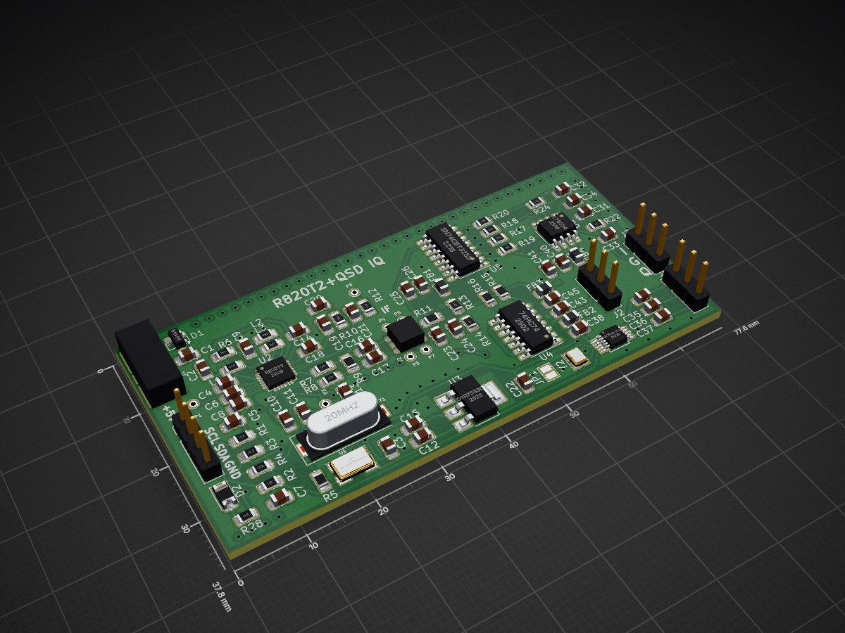
 gmtii/Prototipo-R820T22
Proyecto 'breakout' de un R820T2 más un QSD para obtener salida IQ directamente a la tarjeta de sonido del PC. La idea es experimentar con el R820T2 y un QSD cuya frecuencia de refencia es 4X a la de demodulación…
R820t2 breakout is an open-source printed circuit board by gmtii, from the gmtii/Prototipo-R820T2 repository on GitHub, published under the MIT licence. It is a 2-layer board of 77.6 × 37.8 mm with 99 parts on 74 nets, routed with 504 tracks and 134 vias.
It is built around the 74HC74D, LD1117S33CTR-HXY and SN74CBT3253D, with the SI5351A-B-GT and BAV99 among its other parts. Its parts include 42 capacitors, 25 resistors, 12 connectors, 7 ICs and 3 inductors. It belongs with the interfaces and adapters boards of this library.


Proyecto 'breakout' de un R820T2 más un QSD para obtener salida IQ directamente a la tarjeta de sonido del PC. La idea es experimentar con el R820T2 y un QSD cuya frecuencia de refencia es 4X a la de demodulación, generada por un Si5351.
El proyecto contiene:
Carpeta KICAD: esquemas y PCB directos para generar gerbers.
Carpeta r820t2: código Arduino para controla el R820T2 y Si5351.
Existe un modo consola de comandos serial para controlar los registros del R820T2 directamente y experiemntar.
Modo CAT para controlar la frecuencia de sintonía a través de OMNIRIG y el HDSDR por ejemplo.
Los principales aspectos del diseño son:
El principio de hardware es:
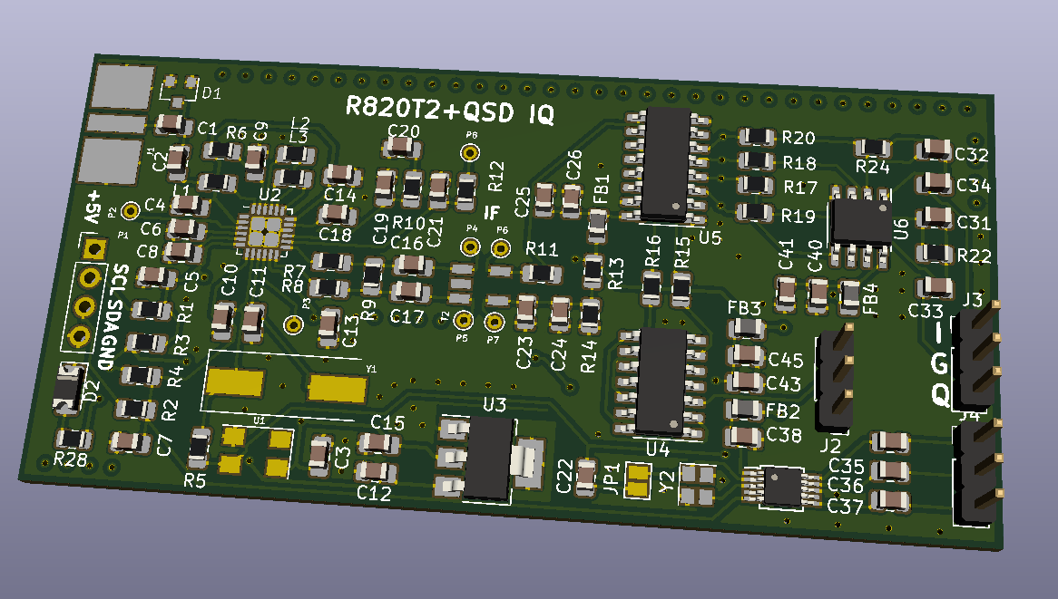
Modelo 3D de la placa PCB mediante KICAD:
El proyecto está basado en fuentes como:
Driver del kernel linux del R820T2 ofrecido bajo licencia GPL. Datasheet del R820T2. Breakout y fuentes del proyecto del R820T2 de Eric Brombaugh https://github.com/emeb/r820t2/. Licencia MIT.
Esteban EA8DGL estebanjbs < at > gmail.com
Breakout project of an R820T2 plus a QSD to get IQ output directly to the PC sound card. The idea is to experiment with the R820T2 and a QSD whose reference frequency is 4X that of demodulation, generated by a Si5351.
The project contains:
KICAD folder: diagrams and direct PCBs to generate gerbers.
r820t2 folder: Arduino code to control the R820T2 and Si5351.
There is a serial command console mode to control the registers of the R820T2 directly and experiment.
CAT mode to control the tuning frequency through OMNIRIG and HDSDR for example.
The main aspects of the design are:
The hardware principle is:
3D model of the PCB board using KICAD:
! [pcb] (pcb.PNG)
The project is based on sources such as:
R820T2 Linux kernel driver offered under the GPL license. Datasheet of the R820T2. Breakout and sources for Eric Brombaugh's R820T2 project https://github.com/emeb/r820t2/. MIT license.
Esteban EA8DGL estebanjbs gmail.com
| Qty | Value | Footprint | References |
|---|---|---|---|
| 10 | 0.1uf | Capacitor_SMD:C_0805_2012Metric_Pad1.15x1.40mm_HandSolder | C3, C4, C8, C9, C13, C14, C16, C17, C18, C21 |
| 9 | 100nF | Capacitor_SMD:C_0805_2012Metric | C22, C23, C25, C35, C36, C37, C38, C40, C43 |
| 7 | CONN_01X01 | Connect:PINTST | P2, P3, P4, P5, P6, P7, P8 |
| 4 | 100 | Resistor_SMD:R_0805_2012Metric | R17, R18, R19, R20 |
| 4 | 220 | Resistor_SMD:R_0805_2012Metric_Pad1.15x1.40mm_HandSolder | R1, R2, R7, R8 |
| 4 | 27pf | Capacitor_SMD:C_0805_2012Metric_Pad1.15x1.40mm_HandSolder | C5, C7, C10, C11 |
| 4 | 33nF | Capacitor_SMD:C_0805_2012Metric | C27, C28, C29, C30 |
| 4 | 4.7uF | Capacitor_SMD:C_0805_2012Metric | C24, C26, C41, C45 |
| 4 | Ferrite_Bead | Inductor_SMD:L_0805_2012Metric | FB1, FB2, FB3, FB4 |
| 3 | 10k | Resistor_SMD:R_0805_2012Metric | R22, R25, R26 |
| 2 | 0 | Resistor_SMD:R_0805_2012Metric | R15, R16 |
| 2 | 0 | Resistor_SMD:R_0805_2012Metric_Pad1.15x1.40mm_HandSolder | R5, R11 |
| 2 | 10uf | Capacitor_SMD:C_0805_2012Metric_Pad1.15x1.40mm_HandSolder | C12, C15 |
| 2 | 150nh | Resistor_SMD:R_0805_2012Metric_Pad1.15x1.40mm_HandSolder | L2, L3 |
| 2 | 2.2uF | Capacitor_SMD:C_0805_2012Metric | C33, C34 |
| 2 | 330p | Capacitor_SMD:C_0805_2012Metric | C31, C32 |
| 2 | 330pf | Capacitor_SMD:C_0805_2012Metric_Pad1.15x1.40mm_HandSolder | C2, C19 |
| 2 | 4k7 | Resistor_SMD:R_0805_2012Metric_Pad1.15x1.40mm_HandSolder | R3, R4 |
| 2 | 5.6k | Resistor_SMD:R_0805_2012Metric | R13, R14 |
| 2 | CLK Source | Connector_PinHeader_2.54mm:PinHeader_1x03_P2.54mm_Vertical | J2, J4 |
| 1 | 0.01uf | Capacitor_SMD:C_0805_2012Metric_Pad1.15x1.40mm_HandSolder | C1 |
| 1 | 10 | Resistor_SMD:R_0805_2012Metric_Pad1.15x1.40mm_HandSolder | R6 |
| 1 | 10k | Resistor_SMD:R_0805_2012Metric_Pad1.15x1.40mm_HandSolder | R12 |
| 1 | 1k8 | Resistor_SMD:R_0805_2012Metric_Pad1.15x1.40mm_HandSolder | R10 |
| 1 | 1uf | Capacitor_SMD:C_0805_2012Metric_Pad1.15x1.40mm_HandSolder | C6 |
| 1 | 20MHz | Crystals:Crystal_SMD_HC49-SD | Y1 |
| 1 | 512 | Resistor_SMD:R_0805_2012Metric | R28 |
| 1 | 6800pf | Capacitor_SMD:C_0805_2012Metric_Pad1.15x1.40mm_HandSolder | C20 |
| 1 | 74HC74 | Package_SO:SOIC-14_3.9x8.7mm_P1.27mm | U4 |
| 1 | 8.2k | Resistor_SMD:R_0805_2012Metric | R24 |
| 1 | 8.2nH | Resistor_SMD:R_0805_2012Metric_Pad1.15x1.40mm_HandSolder | L1 |
| 1 | BAV99 | TO_SOT_Packages_SMD:SOT-23 | D1 |
| 1 | CONN_01X04 | Pin_Headers:Pin_Header_Straight_1x04_Pitch2.54mm | P1 |
| 1 | Conn_01x03_Male | Connector_PinHeader_2.54mm:PinHeader_1x03_P2.54mm_Vertical | J3 |
| 1 | Crystal_GND24 | Crystal:Crystal_SMD_2520-4Pin_2.5x2.0mm | Y2 |
| 1 | DNI | Resistor_SMD:R_0805_2012Metric_Pad1.15x1.40mm_HandSolder | R9 |
| 1 | LD1117S33CTR | Package_TO_SOT_SMD:SOT-223 | U3 |
| 1 | LED | Diode_SMD:D_1206_3216Metric | D2 |
| 1 | LT6234 | Package_SO:SOIC-8_3.9x4.9mm_P1.27mm | U6 |
| 1 | R820T2 | Package_DFN_QFN:QFN-24-1EP_4x4mm_P0.5mm_EP2.65x2.65mm_ThermalVias | U2 |
| 1 | SMA | footprints:SMA_END | J1 |
| 1 | SN74CBT3253 | Package_SO:SOIC-16_3.9x9.9mm_P1.27mm | U5 |
| 1 | Si5351A-B-GT | Package_SO:MSOP-10_3x3mm_P0.5mm | U7 |
| 1 | SolderJumper_2_Open | Jumper:SolderJumper-2_P1.3mm_Open_Pad1.0x1.5mm | JP1 |
| 1 | TRANSFO4 | footprints:Pulse_SMD_Balun | T2 |
| 1 | TWEAALSANF-28.800000 | Crystals:Crystal_SMD_Abracon_ABM3C-4pin_5.0x3.2mm | U1 |
Dizzerin/Software-Defined-Radio
Quadrature sampling down converter software defined radio

KonradMcClure/SDR_Receiver
Software Defined Radio Receiver designed together with Caleb Froelich (https://github.com/froeca) for our Walla Walla University Electronics II project.

pricna/Software-Defined-Radio-Receiver
Software Defined Radio receiver created for Engineering Electronics II at Walla Walla University.


jaronbrown/SDR_Receiver_Design
The microPython module to control the SI5351, si5351.py, was provided by https://github.com/thaaraak/Tinypico-Radio/tree/master.

JoshuaMularczyk/Software_Defined_Radio_Receiver
This project was taken on with the goal to create a Software Defined Radio (SDR) in coolaboration with my partner Christian Williams.

brucemack/sdr2
This is a homebrew SDR rig with no dependency on external computers/soundcards/etc.

cernohorsky/DeltaSDR
HF Software Defined Radio Transceiver that includes ADC and DAC circuits. No soundcard is needed. Board communicates only trough one USB cable.
It measures 77.6 × 37.8 mm and has 2 copper layers, 1.6 mm thick.
99 parts, built around the 74HC74D, LD1117S33CTR-HXY, SN74CBT3253D and SI5351A-B-GT. The full list of its parts is on this page, with links to each part's symbol and footprint where PCBKit's library has them.
From the gmtii/Prototipo-R820T2 repository on GitHub, at the commit this page was made from: the board is KICAD/r820t2_breakout.kicad_pcb. PCBKit opens the board in the browser, with nothing to install.
Its repository publishes it under the MIT licence: you may reuse it on that licence's terms (keep the author's notice, and for a copyleft licence share your changes alike).