10 layers224.5 × 160 mm
Haasoscope pro adc fpga board
drandyhaas/HaasoscopePro
Affordable 2 GHz 3.2 GS/s 12 bit open-source open-hardware expandable USB real-time oscilloscope
586 parts485MIT

 jamarju/c64-psu53
Efficient Commodore 64 power supply with overvoltage + overcurrent protection
C64-psu is an open-source printed circuit board by jamarju, from the jamarju/c64-psu repository on GitHub. It is a 2-layer board of 116 × 74 mm with 50 parts on 27 nets, routed with 155 tracks and 20 vias.
It is built around the LMR33630ADDA, MAX6399ATA and KBU8B. Its parts include 6 connectors, 5 resistors, 3 fuses, 2 capacitors and 2 ICs. It belongs with the power and retro computing and games boards of this library.


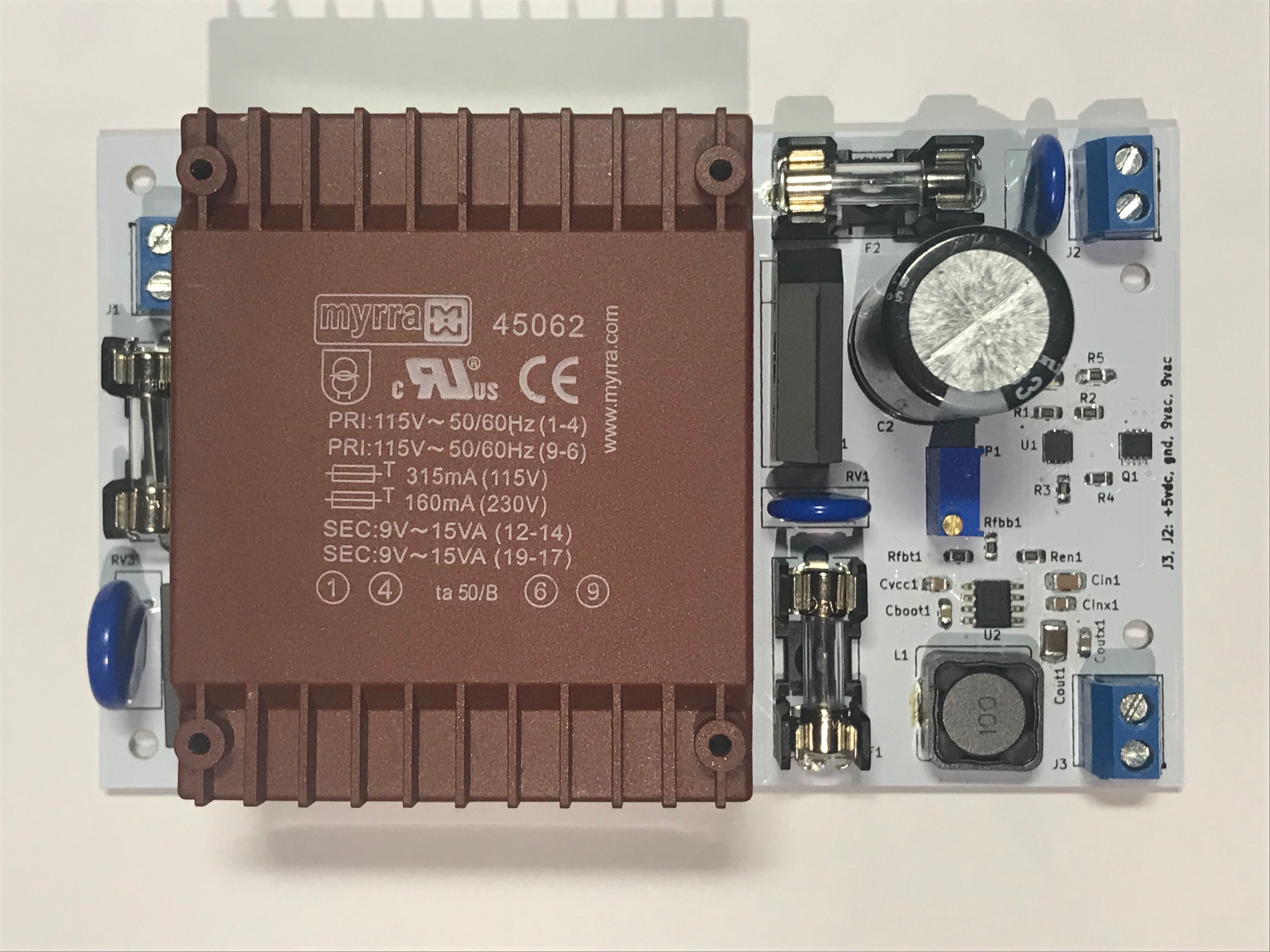
This is a compact and efficient 9VAC/5VDC power supply for the Commodore 64 with the following features:
The kicad-project/gerbers folder contains gerber files ready for production. These are my recommended PCB specifications:
Beware there are three SMD components with thermal pads on the base that can't be easily soldered with a regular iron. You'll need solder paste and an oven or a heat gun for these.
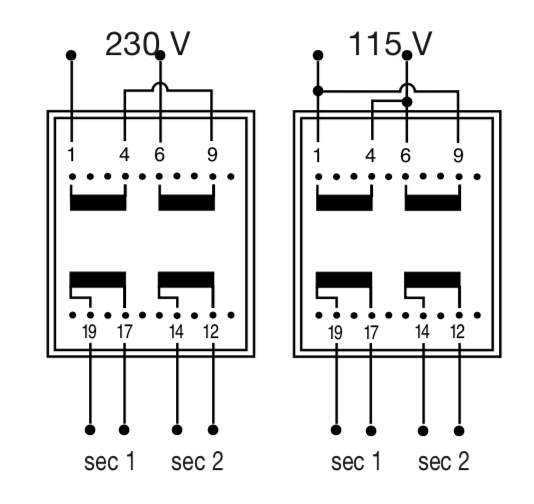
To work at 110 VAC, do these modifications to the schematic:
Start adjusting trimpot TP1 to get 5 VDC with no load.
Then check the voltage at the C64 input with the computer on. You should expect a bit less than 5V due to losses depending on the cable gauge and DIN connectors. Ideally you should aim at 5.0V but a bit of undervoltage (4.9V) appears to work okay on my C64 and will lower heat dissipation.
Output voltage can be adjusted in the [4.13V, 5.55V] range.
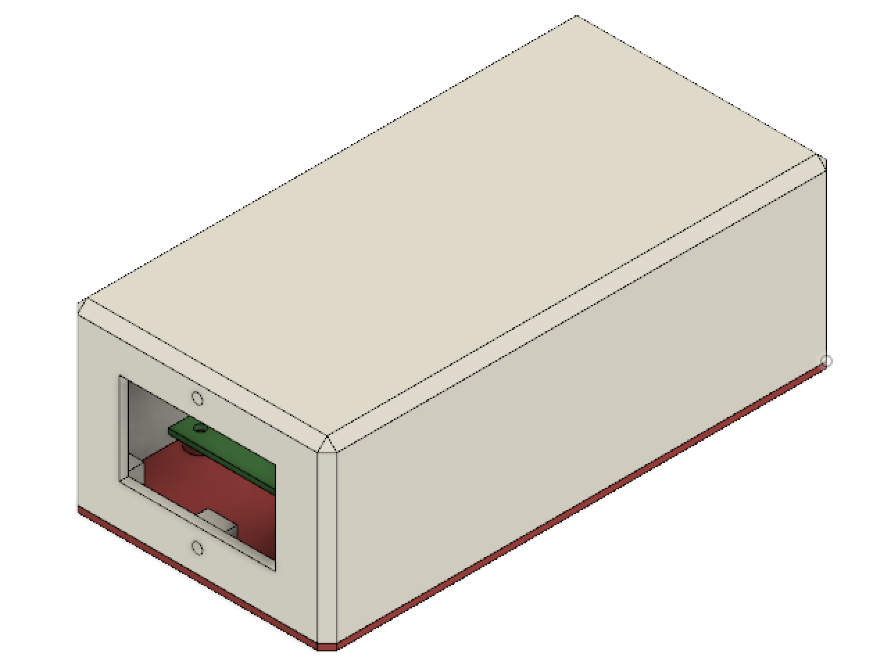
STLs and Fusion 360 project included in the enclosure/ folder. Sorry FreeCAD, I tried to keep this opensource but bodies in 0.17 are just not mature enough and doing this in 0.16 was too painful.
For the enclosure, in addition to the BOM components, you'll need:
I recommend keeping the C64-side cable as short and thick as possible. I recommend 20 AWG, 1 meter long wires.
The expected loss over 1 meter of 20 AWG wire at 5VDC and 1A is 33 mV per leg or 67 mV round trip.
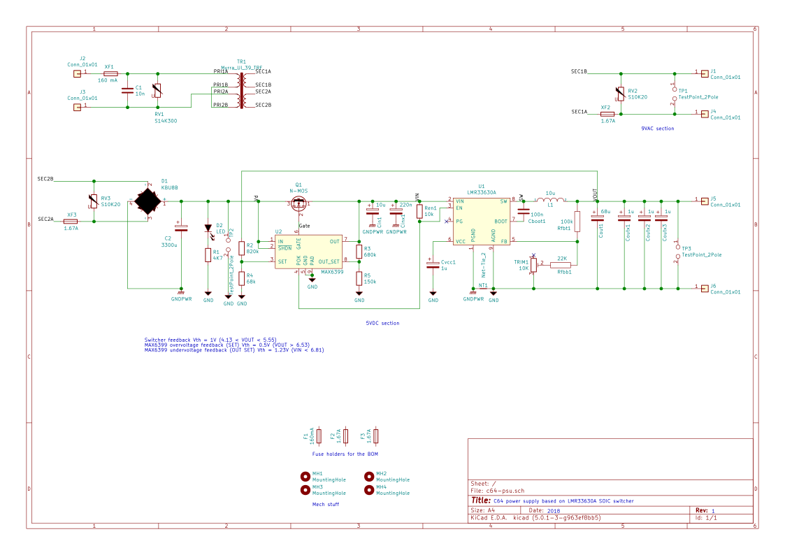
This PSU uses a 9VAC, 30VA dual secondary (15 VA + 15 VA) transformer that provides up to 1.67 amps on each secondary.
The regulator is a TI LMR33630 switching DC/DC step down converter with a switching frequency ~400 KHz and a peak efficiency of 93%.
To prevent an overvoltage situation due to failure of the swithing regulator or the feedback network, a MAX6399 voltage supervisor is used to control a high side P-channel MOSFET at the input of the switcher. When an overvoltage condition (Vout >6.5V) is detected, the MAX6399 pulls the gate of the MOSFET down and cuts the regulator input until the power is completely removed from the unit.
The MAX6399 also provides undervoltage protection for clean startup of the switcher.
In addition to the over/undervoltage supervisor 3 varistors (MOVs) provide surge protection on the primary and both secondaries and 3 fuses prevent prolonged overcurrent condition on both sides of the transformer. The switcher itself also has an instant overcurrent protection above 3A.
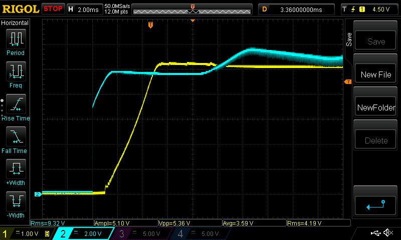
Test conditions: Vout=5.1V, Iout=1A.
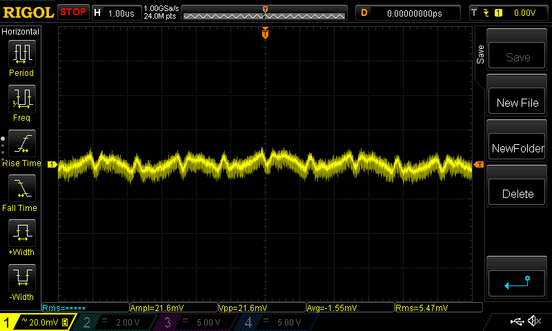
Overvoltage protection voltage threshold set at Vout >= 6.53V via R1/R2 divider.
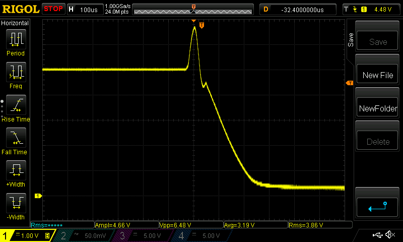
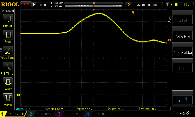
Test conditions: shorted feedback input of LMR33630 to GND during normal operation at Vout=5.1V, Iout=1A.
@ 100 us per division:
@ 10 us per division:
Nominal Vout: 5.10V Overshoot: 5.36V (<10 ms)
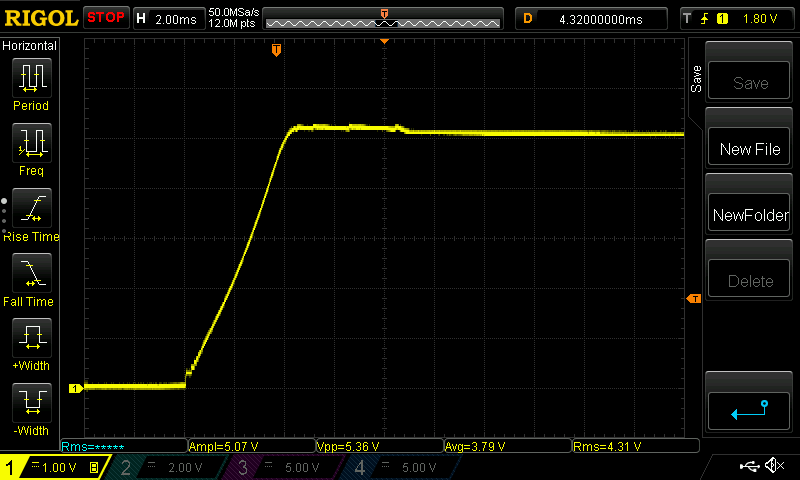
Undervoltage protection voltage threshold set at Vin <= 6.81V via R3/R4 divider.
CC-BY-NC-SA (Attribution-NonCommercial-ShareAlike).
See LICENSE.txt for details.
Please do not mass (?) produce this without my permission.

| Qty | Value | Footprint | References |
|---|---|---|---|
| 6 | Conn_01x01 | c64-psu:spade_4.8mm | J1, J2, J3, J4, J5, J6 |
| 4 | 1u | Capacitor_SMD:C_0805_2012Metric_Pad1.15x1.40mm_HandSolder | Coutx1, Coutx2, Coutx3, Cvcc1 |
| 4 | MountingHole | MountingHole:MountingHole_3.2mm_M3 | MH1, MH2, MH3, MH4 |
| 3 | TestPoint_2Pole | TestPoint:TestPoint_2Pads_Pitch2.54mm_Drill0.8mm | TP1, TP2, TP3 |
| 2 | 1.67A | c64-psu:20mm fuse | F2, F3 |
| 2 | S10K20 | Varistor:RV_Disc_D12mm_W4.5mm_P7.5mm | RV2, RV3 |
| 1 | 1.67A | Fuse:Fuseholder_Cylinder-5x20mm_Schurter_0031_8201_Horizontal_Open | XF3 |
| 1 | 100k | Resistor_SMD:R_0805_2012Metric_Pad1.15x1.40mm_HandSolder | Rfbt1 |
| 1 | 100n | Capacitor_SMD:C_0805_2012Metric_Pad1.15x1.40mm_HandSolder | Cboot1 |
| 1 | 10K | Potentiometer_THT:Potentiometer_Bourns_3296Y_Vertical | TRIM1 |
| 1 | 10k | Resistor_SMD:R_0805_2012Metric_Pad1.15x1.40mm_HandSolder | Ren1 |
| 1 | 10n | Capacitor_THT:C_Rect_L19.0mm_W5.0mm_P15.00mm_MKS4 | C1 |
| 1 | 10u | Capacitor_SMD:C_1206_3216Metric_Pad1.42x1.75mm_HandSolder | Cin1 |
| 1 | 10u | Inductor_SMD:L_Bourns_SRR1260 | L1 |
| 1 | 150k | Resistor_SMD:R_0805_2012Metric_Pad1.15x1.40mm_HandSolder | R5 |
| 1 | 160 mA | Fuse:Fuseholder_Cylinder-5x20mm_Schurter_0031_8201_Horizontal_Open | XF1 |
| 1 | 160mA | c64-psu:20mm fuse | F1 |
| 1 | 220n | Capacitor_SMD:C_0805_2012Metric_Pad1.15x1.40mm_HandSolder | Cinx1 |
| 1 | 22K | Resistor_SMD:R_0805_2012Metric_Pad1.15x1.40mm_HandSolder | Rfbb1 |
| 1 | 3300u | Capacitor_THT:CP_Radial_D18.0mm_P7.50mm | C2 |
| 1 | 4K7 | Resistor_SMD:R_1206_3216Metric_Pad1.42x1.75mm_HandSolder | R1 |
| 1 | 680k | Resistor_SMD:R_0805_2012Metric_Pad1.15x1.40mm_HandSolder | R3 |
| 1 | 68k | Resistor_SMD:R_0805_2012Metric_Pad1.15x1.40mm_HandSolder | R4 |
| 1 | 68u | Capacitor_SMD:C_1210_3225Metric_Pad1.42x2.65mm_HandSolder | Cout1 |
| 1 | 820k | Resistor_SMD:R_0805_2012Metric_Pad1.15x1.40mm_HandSolder | R2 |
| 1 | Fuse Holder | Fuse:Fuseholder_Cylinder-5x20mm_Schurter_0031_8201_Horizontal_Open | XF2 |
| 1 | KBU8B | Diode_THT:Diode_Bridge_Vishay_KBU | D1 |
| 1 | LED | LED_SMD:LED_1206_3216Metric_Pad1.42x1.75mm_HandSolder | D2 |
| 1 | LMR33630A | Package_SO:TI_SO-PowerPAD-8_ThermalVias | U1 |
| 1 | LOGO | c64-psu:linkballoon | G*** |
| 1 | MAX6399 | Package_DFN_QFN:DFN-8-1EP_3x3mm_P0.65mm_EP1.55x2.4mm | U2 |
| 1 | Myrra_UI_39_TRF | c64-psu:Myrra UI 39 trf | TR1 |
| 1 | N-MOS | c64-psu:LFPAK33-PSMN7R5-30MLD | Q1 |
| 1 | Net-Tie_2 | NetTie:NetTie-2_THT_Pad1.0mm | NT1 |
| 1 | S14K300 | Varistor:RV_Disc_D15.5mm_W5.2mm_P7.5mm | RV1 |
drandyhaas/HaasoscopePro
Affordable 2 GHz 3.2 GS/s 12 bit open-source open-hardware expandable USB real-time oscilloscope

Andre1Becker/GalvOS
Open-source ESP32-S3 laser show controller — built to replace proprietary OEM controllers in RGB galvo laser projectors

Coen-Lab/exp-control-board
Hardware and firmware for an experimental control board for scientific rigs

ErdemA33/stm32f405-flight-controller
Open-source ArduPilot-compatible flight controller for fixed-wing UAVs. STM32F405, 4-layer KiCad design, built in 5 modular stages.

lhr-solar/PS-MotorControllerInterfacePCB
Provides power conversion/protection and fan control for the Prohelion WaveSculptor 22 motor controller

kfilipekk/iridium_drone
STM32H743 flight controller that navigates without GPS from Iridium satellite Doppler

KareemOye/USB_POWER_SUPPLY_PCB
12 V to 5 V USB step-down supply based on the LM2596-ADJ, designed in KiCad

lhr-solar/PS-PumpController
Controls speed of liquid cooling pump and fans for the main battery pack. Additionally, interprets data from temperature sensors and flowrate sensors for fan/pump control loop
It measures 116 × 74 mm and has 2 copper layers, 1.6 mm thick.
50 parts, built around the LMR33630ADDA, MAX6399ATA and KBU8B. The full list of its parts is on this page, with links to each part's symbol and footprint where PCBKit's library has them.
From the jamarju/c64-psu repository on GitHub, at the commit this page was made from: the board is kicad-project/c64-psu.kicad_pcb. PCBKit opens the board in the browser, with nothing to install.
Its repository states no licence, so its author keeps all rights: ask jamarju before reusing the design.