2 layers97 × 72.8 mm

 ill-ev-concept/EVC-PCB
All new PCBs for EV Concept
Brushed v2 is an open-source printed circuit board by ill-ev-concept, from the ill-ev-concept/EVC-PCB repository on GitHub, published under the MIT licence. It is a 4-layer board of 108.5 × 92.8 mm with 68 parts on 74 nets, routed with 328 tracks and 436 vias.
It is built around the ISO1042QDWVQ1, AD8410AWBRZ-RL and MIC4606-1YML-TR, with the LSF0102DCUR, TC1108-3.3VDBTR and NTBLS4D0N15MC among its other parts. Its parts include 17 capacitors, 13 resistors, 7 ICs, 4 diodes and 4 transistors. It belongs with the STM32 boards of this library.


By: Himesh Nasaka
Welcome to EV Concept's PCB Repo!
This is where all of our projects are stored.
Start by having Git and KiCAD 10 downloaded. If you are using a older version of KiCAD, we recommend updating to the newest version. We also recommend installing Github Desktop in order to make the usage a bit cleaner.
Clone this repo. This can be either done through terminal or Github Desktop. Click the green dropdown labeled "<> Code" and select your preference of how to clone the repo. If using terminal, run the command below
git clone [INSERT]
If using Desktop, you can click the dropdown menu next to current repository, then "add", and finally "clone" where we can input the repo's url.
After cloning, open KiCAD and find the "Preferences" dropdown and select "Configure Paths".
We are going to be adding three new paths. Create three new variables, EVC_SYMBOL_DIR, EVC_FOOTPRINT_DIR, and EVC_3DMODEL_DIR. Link these to the location of the symbols, footprints, and 3d_models folders contained with libs folder.

When designing, we will need KiCAD to know to look at a given library. We can do this by going to "Preferences" and finding either "Manage Symbol Libraries" or "Manage Footprint Libraries". Opening either brings up a window where we can select "Project Specific Libraries" where we can add paths. Click the folder icon and add the wanted library. If you set the path up correctly, the library path will contain ${EVC_SYMBOL_DIR}, ${EVC_FOOTPRINT_DIR}, or ${EVC_3DMODEL_DIR}.

In order to begin designing, create a branch for your given board. This can be done through either the "current branch" dropdown in Desktop or using the command git checkout -b [branch name]. You can swap branches using the same dropdown or either git checkout [branch name].
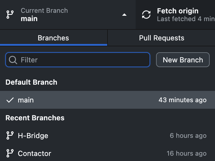
This will be the branch where you will be doing your design work. Create a new KiCAD project and save the location into the boards folder of this repo. Everything onward will be traditional git. Use git add or check off the needed boxes on Desktop to add files for commit. git commit -m "[MESSAGE HERE]" will commit your changes. Make sure to write a meaningful commit message in order for good documentation. An example is shown below.
git commit -m "Finished designing LDO and CANBus connectors, need to add MCU pinout and decoupling caps"
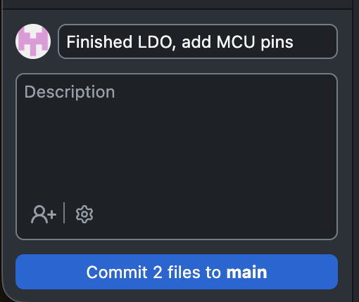
Input both your contributions and the next required steps in order to give reminders to both yourself and your teammates.
Once a board is finished or you want it reviewed, it must be submitted via a pull request. This can be done using git push -u origin [branch name] or by clicking the branch dropdown in Desktop and selecting the "create pull request" option.
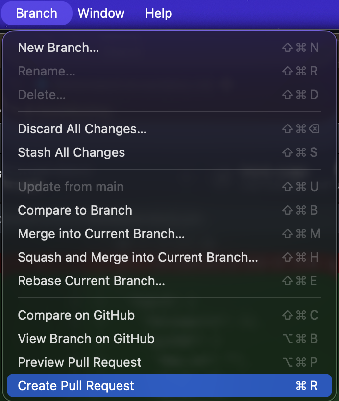
This will open up a Github tab on your browser where you can edit your pull request. Give it a good title and description so the design choices are clear and understandable. A title will also help the leads parse what you guys want done.
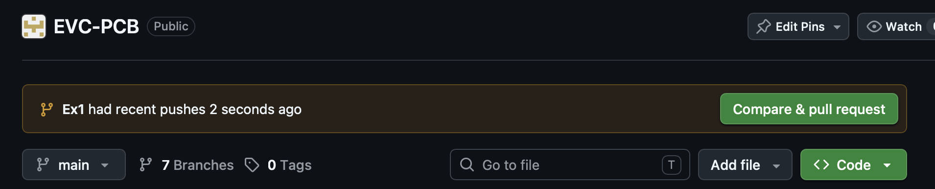
You'll see the image above if you use a command line prompt and go to the repo.
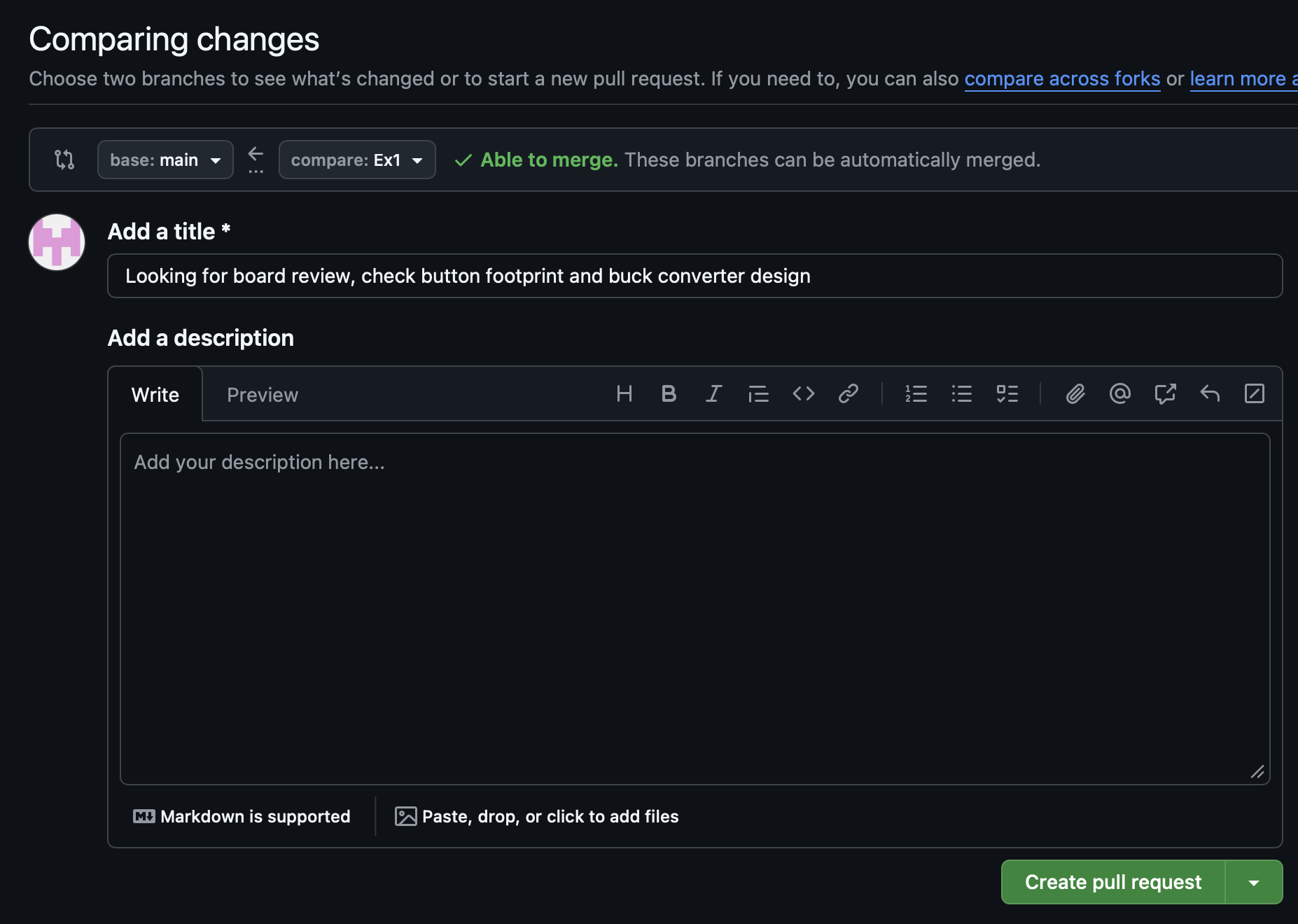
After the PR is submitted, we will decide on whether the board can be pushed to main or not. If it is not pushed, we will submit comments on what needs to be reviewed and edited. You can view open PRs and their comments in Github.
Apart from designing in KiCAD, it is important to be updating the libs folder when any new schematic, footprint, or model is added. First make sure the IC you want to add isn't currently within our library. Add the path to the specific library which is detailed more above. If the IC is not located in it's library, open Symbol/Footprint editor and select the library you want to add to. I recommended clicking the "View" dropdown, selecting the "Panels" option and adding the "Library Tree" option in order to easily see the connected libraries.
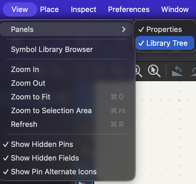
From this, import the downloaded model and save the file. From there, push the updated library files and create a pull request. The leads will then check your work and merge it into main so everyone can use the IC.
When making pull requests for ICs, make sure to push them individually rather than with changes to other files. This will make it more clear for reviewers to understand that library files are being edited in addition to making sure that the change will be pushed to main. If you push with changes to your board and the pull request is not granted, people will not have access to the IC you have imported.
Because the libs folder will be constantly updated, its also important to keep your branch up to date with new changes. We can layer on changes from main into our branch using a few different methods but the main one we will be using is merge. Run the command git fetch origin and then git merge origin in order to update changes. In Desktop, you can select "Update from main" from the "Branch" dropdown.
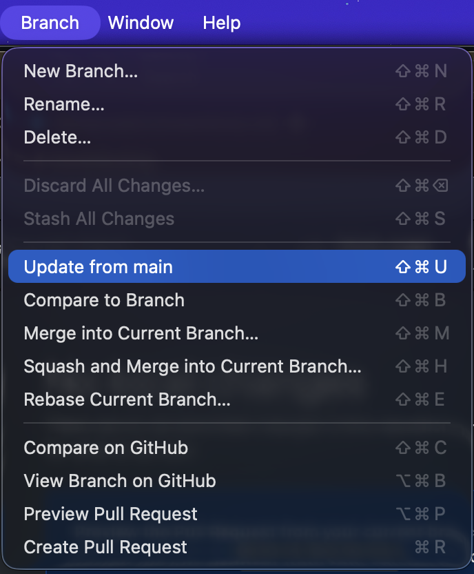
This should not change any local files that is stored and will update the libs folder to have the newest selection of ICs. I recommend doing this every time you work on your boards. It will also make sure a merge conflict won't be created, in which the same file from two different pull requests is edited, causing a lot of hassle for the writers of this repo.
A general outline of what the workflow may look like is shown below:
git checkout [branch name] -> Run this to swap to the branch you want to work on
git fetch origin -> Run this to pull updates from main. Important for having updated libs
git merge origin/main -> Merges the changes from the above command
git add [file name] -> Add files for commit. When updating library files, make sure to add them in individual PRs
git commit -m "[message here]" -> Commits your changes to be pushed into your branch
git push -u origin [branch name] -> Run this command the first time you make the branch. It will link your branch to Github.
git push -> Pushes your changes. After, you can go to Github and create a pull request for the changes to be pushed into main. Don't create a PR for every change you do. Only create pull requests IF you are editing the libs folder OR you are submitting for board revision OR it is the final revision of the board.
| Qty | Value | Footprint | References |
|---|---|---|---|
| 10 | 0.1uF | Capacitor_SMD:C_0402_1005Metric | C3, C4, C8, C11, C12, C13, C14, C15, C16, C17 |
| 4 | 10 | Resistor_SMD:R_0603_1608Metric | R5, R6, R7, R8 |
| 4 | MountingHole | MountingHole:MountingHole_4.3mm_M4 | H1, H2, H3, H4 |
| 4 | NTBLS4D0N15MC | High Power MOSFETs:NTBLS4D0N15MC | Q1, Q2, Q3, Q4 |
| 2 | 10k | Resistor_SMD:R_0402_1005Metric | R4, R9 |
| 2 | 1k | Resistor_SMD:R_0402_1005Metric | R10, R11 |
| 2 | 1uF | Capacitor_SMD:C_0402_1005Metric | C9, C10 |
| 2 | 200k | Resistor_SMD:R_0402_1005Metric | R2, R3 |
| 2 | 3 | Resistor_SMD:R_0603_1608Metric | R12, R13 |
| 2 | 470uF | Capacitor_THT:CP_Radial_D10.0mm_P7.50mm | C5, C6 |
| 2 | LED | Capacitor_SMD:C_0603_1608Metric | D1, D2 |
| 2 | LSF0102DCUR | Package_SO:SSOP-8_2.95x2.8mm_P0.65mm | U2, U3 |
| 2 | MountingHole | MountingHole:MountingHole_3mm | H5, H6 |
| 2 | SS1200 | Diode_SMD:D_SMA | D3, D4 |
| 1 | .001 | Resistor_SMD:R_2512_6332Metric | R1 |
| 1 | 12V+ | ThreadedConnector:WP-BUTR_7460307 | +12V |
| 1 | 1uF | Capacitor_SMD:C_0603_1608Metric | C2 |
| 1 | 1uf | Capacitor_SMD:C_0603_1608Metric | C1 |
| 1 | 4.7uF | Capacitor_SMD:C_0402_1005Metric | C18 |
| 1 | AD8410AWBRZ-RL | Package_SO:MSOP-8_3x3mm_P0.65mm | IC3 |
| 1 | CANBus | Connector_RJ:RJ45_Amphenol_54602-x08_Horizontal | J5 |
| 1 | Debug Throttle | Potentiometers THD:P120PKY25BR10K | RV2 |
| 1 | Encoder | Connector_PinHeader_2.54mm:PinHeader_1x05_P2.54mm_Vertical | J6 |
| 1 | ISO1042QDWVQ1 | CAN Isolators & Trancievers:DWV0008A-IPC_A | IC1 |
| 1 | LOGO | EVC Logo:Phineas | G*** |
| 1 | LOGO | EVC Logo:EVC_LOGO | G*** |
| 1 | LOGO | EVC Logo:Jeremy | G*** |
| 1 | LOGO | EVC Logo:holypeak | G*** |
| 1 | LOGO | EVC Logo:PERRY | G*** |
| 1 | LOGO | EVC Logo:DOCTOR | G*** |
| 1 | LOGO | EVC Logo:Ferb | G*** |
| 1 | MIC4606-1YML-TR | Package_DFN_QFN:QFN-16-1EP_4x4mm_P0.65mm_EP2.5x2.5mm | IC2 |
| 1 | Motor+ | ThreadedConnector:WP-BUTR_7460307 | M- |
| 1 | Motor- | ThreadedConnector:WP-BUTR_7460307 | M+ |
| 1 | Prog_Header | Connector_PinHeader_2.54mm:PinHeader_2x05_P2.54mm_Vertical | J7 |
| 1 | STM32F103C8Tx | Package_QFP:LQFP-48_7x7mm_P0.5mm | U1 |
| 1 | TC1108-3.3VDBTR | Package_TO_SOT_SMD:SOT-223 | IC4 |
| 1 | UART | Connector_PinHeader_2.54mm:PinHeader_1x03_P2.54mm_Vertical | J8 |
| 1 | V+ | ThreadedConnector:WP-BUTR_7460307 | +48V |
| 1 | V- | ThreadedConnector:WP-BUTR_7460307 | GND |


CMU-Robotics-Club/robobuggy-pcb
repository for CAD(s) for PCB(s) for Robobuggy.


WheelchairSeniorDesign/PCBs
The PCB designs for the wheelchair for our senior design project

makingdevices/TC-Logger-Device
A thermocouple logger with USB communication
It measures 108.5 × 92.8 mm and has 4 copper layers, 1.6 mm thick.
68 parts, built around the ISO1042QDWVQ1, AD8410AWBRZ-RL, MIC4606-1YML-TR and LSF0102DCUR. The full list of its parts is on this page, with links to each part's symbol and footprint where PCBKit's library has them.
From the ill-ev-concept/EVC-PCB repository on GitHub, at the commit this page was made from: the board is boards/H-Bridge/brushed_v2.kicad_pcb and its schematic boards/Contactor/Contactor.kicad_sch. PCBKit opens the board in the browser, with nothing to install.
Its repository publishes it under the MIT licence: you may reuse it on that licence's terms (keep the author's notice, and for a copyleft licence share your changes alike).