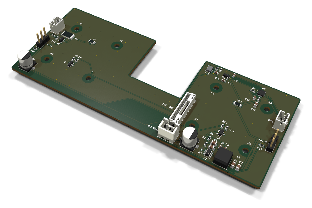
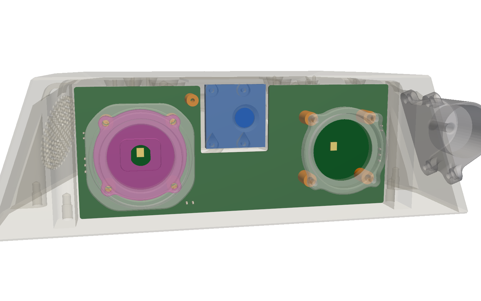
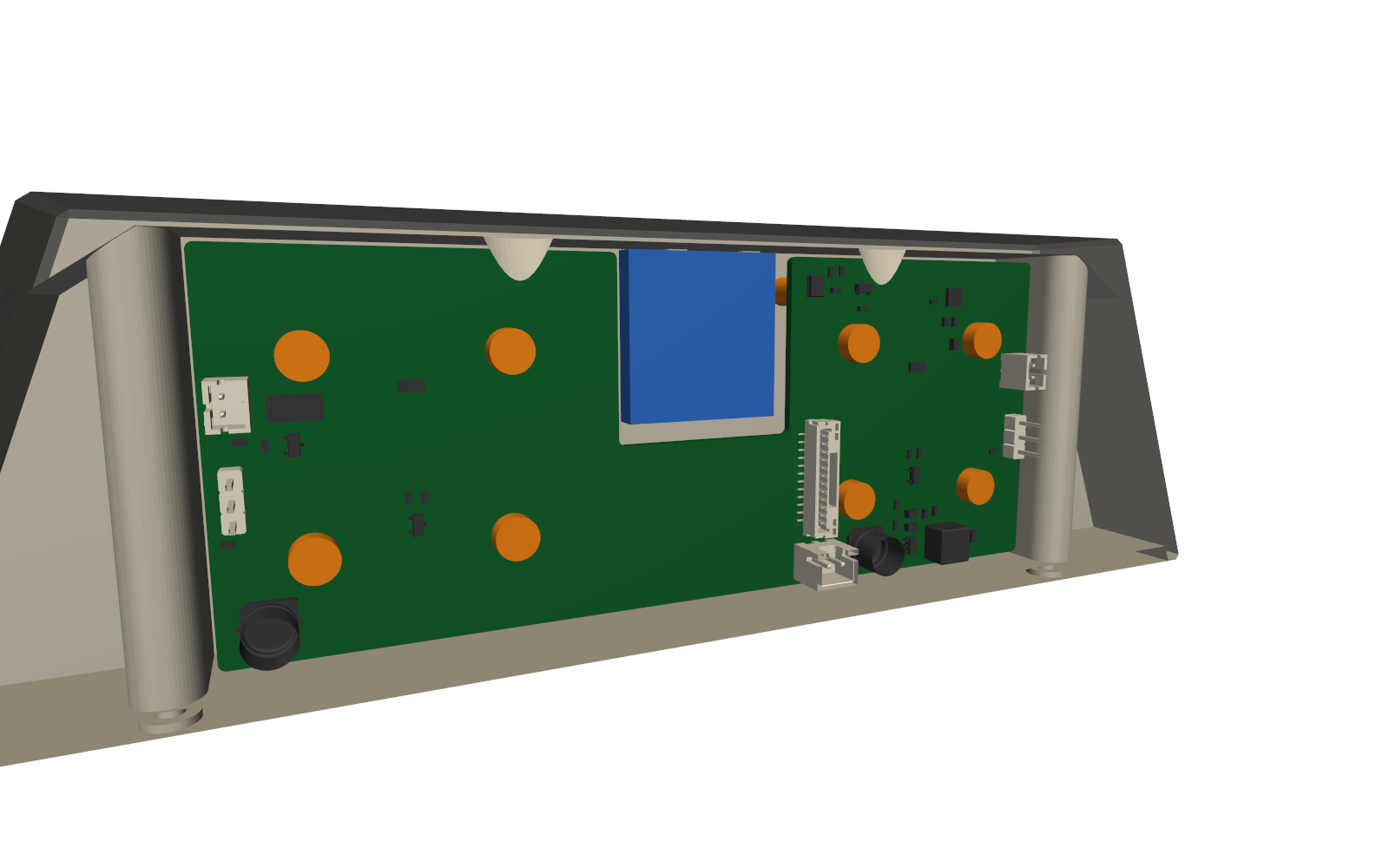
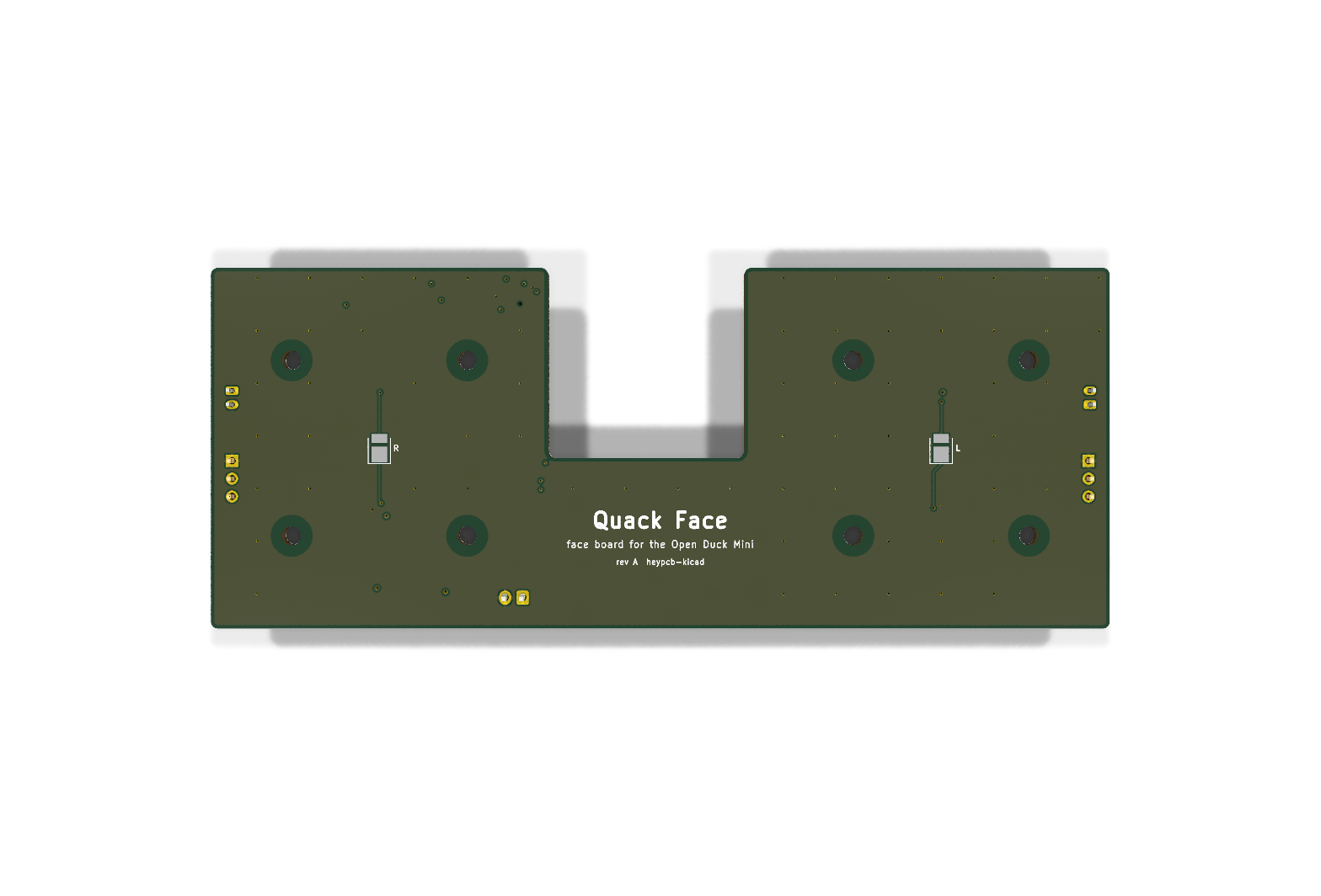
Face board for the Open Duck Mini's head: eye LEDs, projector driver, I2S amp and mic, antenna servos, shaped to the head. 4-layer KiCad 10 board plus printed standoffs, fit-checked in the head CAD.
Quack face is an open-source printed circuit board by HeyPCB, from the HeyPCB/quack-face repository on GitHub, published under the CERN-OHL-S-2.0 licence. It is a 4-layer board of 128 × 51.4 mm with 55 parts on 39 nets, routed with 327 tracks and 86 vias.
It is built around the MAX98357AETE+T, TPS56339DDC and ICS-43434, with the XC6206P332MR-G, M2.5 and CC0603KRX7R9BB104 among its other parts. Its parts include 17 resistors, 13 capacitors, 6 connectors, 4 ICs and 3 transistors. It belongs with the robots and motor control and audio and music boards of this library.
The face board for the Open Duck Mini's head: eye LEDs, projector driver, I2S speaker amp and microphone, antenna servos, shaped to the head.
Part of HeyPCB's open robot boards. Designed end to end with the HeyPCB method on
KiCad 10 (headless pipeline, Freerouting 2.4.1); every number below is measured on the files in this repository.
Mentions of ./run.sh, docs/rules/, blocks/ or parts/ refer to the heypcb-kicad SDK that produced them.
Quack Face is the face board for the Open Duck Mini's head. It stands vertically 8 mm behind the
face wall, on the eight screw holes that hold the duck's eye parts today. Its outward face
carries the two eye LEDs and the microphone's sound port; everything else sits on the face
that looks into the head. It makes its own 5 V from the pack, drives the eyes, the projector,
the speaker and the two antenna servos, and listens through an I2S microphone. It talks to the
Quack Core brain board over one JST-GH 12-pin harness (J12) and takes power on a JST-XH 2-pin
(J13). It was designed with the HeyPCB method on KiCad 10 (10.0.6), by heypcb-kicad's headless
pipeline with Freerouting 2.4.1, from the brief in board.json and the research spec for the
duck (robots/research/duck/spec.md, section 4).
This board has not been fabricated, assembled or powered. Everything below is what KiCad,
the pipeline and cad/parts.py measured on the design files. Nothing here has been tested on
hardware or in the duck. Every gate number comes from report.json, and every
fit number from cad/fit.json, both written by the runs of 2026-10-02.
What it carries
Power: VBAT (2S pack, 6.0-8.4 V, fused 5 A on the Quack Core) on J13, with a 220 uF / 16 V
electrolytic for the 330 mm harness. A TPS56339 buck (4.5-24 V in, 3 A, 500 kHz) makes 5 V
with TI's 5 V divider (52.3k over 10.0k, 0.802 V reference: 4.996 V nominal), a 4.7 uH
inductor and 2 x 22 uF out. TI's 5.6 uH is computed at 19 V in; its inductor equation gives
4.5 uH at the pack's 8.4 V. EN floats, as TI's pin table allows ("Float to enable"). An
XC6206P332MR LDO makes 3.3 V for the microphone.
Eyes: two white 2835 LEDs (XINGLIGHT XL-2835UWC-05, 150 mA / 500 mW maximum) on the
outward face, each centred on its 25 mm eye opening. Each is fed from 5 V through 33 ohm and
switched on its cathode by an AO3400A; the gate takes the Pi's GPIO through 100 ohm and
is held off by 100k. High = on, as eyes.py drives them. From the datasheet's 2.8-3.4 V
forward voltage the 33 ohm sets about 48-67 mA (an estimate: the datasheet gives Vf at
150 mA). The GPIO no longer carries LED current.
Projector: the 1 W emitter stays in its reflector in flash_light_module, outside the
head's left wall. The board switches it the same way: 5 V through a 10 ohm 1 W 2512 to J15
pin 1, an AO3400A on pin 2. About 160-200 mA for a 3.0-3.4 V emitter (estimated; the
emitter's own data is not known).
Speaker: a MAX98357A (I2S, class D, 3.2 W into 4 ohm per its catalogue row) on the
Pi's I2S output. SD_MODE goes to VDD through 1 Mohm: with the datasheet's internal 100k
pull-down that is 0.45 V, inside the (left + right)/2 window. GAIN_SLOT is open (9 dB). VDD
has 10 uF + 100 nF behind a 0603 ferrite bead. The exposed pad is on GND. Speaker on J14.
Microphone: a TDK ICS-43434 I2S MEMS microphone with a bottom port. It shares BCLK and
LRCLK with the amplifier and drives the Pi's DIN (GPIO20) through 47 ohm, with the
datasheet's 100k pull-down. LR is tied low, so it answers in the left half-frame. The part
sits on the inner face and its 0.5 mm sound hole opens on the outward face.
Antenna servos: two 1x3 2.54 mm headers (pin 1 GND, pin 2 5 V, pin 3 PWM, the spec's
order), PWM through 220 ohm, and one 220 uF / 16 V on 5 V beside the left header.
Board: 128.0 x 51.4 mm with a 28.0 x 27.1 mm camera notch and 1 mm fillets (a
board.shape polygon), 4 layers, 1.6 mm. F.Cu (the inner face) is signal with a GND pour,
In1 a GND plane, In2 signal with a 5 V pour, B.Cu (the outward face) a GND pour with two
short LED slots and no other track. Eight 2.7 mm NPTH holes for M2.5.
Which face looks out
The outward face is B.Cu. The pipeline always writes the title on B.SilkS, so making B the
face the viewer sees puts the board's name there with no SDK change. Only the two eye LEDs are
placed with "side": "bottom"; every other part, connectors included, is on F.Cu, facing the
inside of the head where the harness arrives. So the assembler places one face and two LEDs on
the other: a two-sided job at JLC.
On the outward face:
B.Cu takes no tracks (board.keepouts, B.Cu, tracks) except a 3.2 mm slot through each LED.
A 12 mm circle round each LED takes no via, on any layer.
So each LED's anode leaves straight up and its cathode straight down on a short B.Cu track
to a via outside that halo. The two eyes mirror each other.
What remains on that face is the GND pour, the two LEDs, the eight holes, the sound port and
the title, "Quack Face / face board for the Open Duck Mini / rev A heypcb-kicad".
Copper stays 3 mm from every screw-hole centre on both outer faces, so the screw heads and
the printed spacers sit on bare laminate.
A 5 mm circle round the sound hole takes no via, so the printed acoustic boot seals on flat
solder mask.
Connectors
J12, to the Quack Core (JST-GH 12P, BM12B-GHS-TBT vertical, C2983891). The pinout is the
shared contract in the research spec, section 4.5, unchanged. These are the board's nets, read
back from the run's design.json:
Pin
Net
Pi GPIO
Pin
Net
Pi GPIO
1
GND
7
GND
2
I2S_BCLK
18
8
EYE_L
24
3
GND
9
EYE_R
23
4
I2S_LRCLK
19
10
PROJ
25
5
I2S_DOUT (to the amplifier)
21
11
ANT_L
13
6
I2S_DIN (from the microphone)
20
12
ANT_R
12
The GH mounting pads are on GND. DOUT and DIN are named from the Pi's side, as in the contract.
J13, power from the Quack Core (JST-XH 2P, B2B-XH-A, C158012): pin 1 VBAT, pin 2 GND.
Ref
What
Part
Pins
J14
Speaker, 4 ohm
JST-PH 2P B2B-PH-K-S (C131337)
1 OUTP, 2 OUTN (bridge-tied: neither wire to GND)
J15
Projector emitter
JST-PH 2P B2B-PH-K-S (C131337)
1 anode (5 V through 10 ohm), 2 cathode (AO3400A)
J16
Left antenna servo (ANT_L)
1x3 PZ254V-11-03P (C2937625)
1 GND, 2 5 V, 3 PWM
J17
Right antenna servo (ANT_R)
1x3 PZ254V-11-03P (C2937625)
1 GND, 2 5 V, 3 PWM
Placement follows the head:
the projector connector and the left servo header are on the robot-left edge (the
projector's feed-through is in the left wall);
the speaker connector and the right servo header are on the robot-right edge (the speaker
hangs on the right wall);
J12 and J13 are beside the camera notch on the robot's right, where the head leaves about
40 mm behind the board (see the fit table).
Departures from the research spec
Spec
On the board
Why
Microphone hole suggested at CAD (y +20.0, z 160.0)
At (y -20.0, z 160.0), the same spot mirrored
With the mic left of the camera notch, every I2S net had to cross under the notch, and routing left I2S_BCLK open at the mic. On the right, no I2S net crosses it and routing closed (see docs/rules/pipeline.md). The hole clears the eye screws and camera bosses, by the spec's own criteria.
Eye openings at z 139.20
LEDs at z 139.41
cad/parts.py fits the 25.0 mm opening in a section of head.stl and finds it centred at z 139.41, midway between the screw rows (126.91 / 151.91). The LEDs sit on the fitted centre.
JST-GH 12P SM12B-GHS-TB (right-angle; no LCSC number resolved)
BM12B-GHS-TBT, top entry, C2983891 (11 553 in stock)
Found by MPN on the JLC mirror. The side-entry SM12B-GHS-TB is C265421 (519 in stock). The pinout is the contract's either way.
Either on-board emitters or JST-PH to the existing 1 W eyes
On-board white 2835 LEDs at roughly 50-70 mA (estimate above)
The outward face carries the eyes. The stock eyes run from bare GPIO, so their real current is not 330 mA.
M2.5 male-female hex standoffs
Printed 8 mm / 6 mm spacers on M2.5 x 16 through-screws (cad/)
The task asked for printed standoffs. A through-screw clamps eye part, wall (and bulb ring), spacer and board in one stack; see the fit table for its thread engagement.
Optional 74LVC1G125 for a 5 V servo signal
Not fitted
Optional in the spec; the PWM swings 3.3 V through 220 ohm.
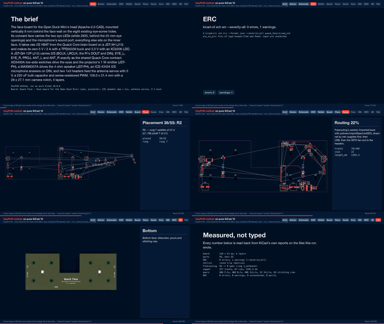
Measured gates (full run with media, 2026-10-02, from report.json)
47 of 47 orderable parts bound, 0 unsourced, 0 identity conflicts. The eight holes are not in the BOM. 14 distinct Extended parts, about $42 in JLC loading fees
ERC (kicad-cli sch erc --severity-all)
0 errors, 1 warning (pin_to_pin: the MAX98357A's exposed pad, an "unspecified" pin, on the GND power net)
Netlist round trip
identical, 33 nets
Freerouting, rung 1, fanout off (kept)
96 → 10 open; the last-mile router closed all 10 (45 tracks, 14 vias, kept on DRC's word) → 0 open
Freerouting, rung 1, fanout on (for comparison)
96 → 8 open; the last mile closed 7 → 1 open
Copper
327 tracks, 22 routing vias, 1392.3 mm of track (F.Cu 977.8, In2 387.5, B.Cu 27.0). No class was narrowed
Pours (only after a measured 0 open)
GND on F.Cu, In1 and B.Cu, 5 V on In2 (board.pours); 65 stitching vias (87 vias in all); 0 open after the pour, after stitching and at the end
Silkscreen
9 words and the 3 title lines placed; 40 designators re-seated and 6 hidden; 1 stitching via displaced
0 errors, 1 warning (213 stock-footprint silk strokes at 0.12 mm; the fab prints them at its 0.15 mm minimum)
Fab gate
ready, no blockers. Four copper gerbers and a gerber job with LayerNumber 4; the JLC CPL corrected 6 rotations and lists D1 and D2 as Bottom
The kept route depends on the last mile: Freerouting alone left 10 connections open, most of
them a few millimetres long (the buck's SW to its boot capacitor, the mic's LR pin to its GND
pin, I2S at J12). The brief routes the same way every run (docs/rules/pipeline.md, "One brief
routes one way"). A change as small as moving both eye halos 0.21 mm left 11 open on the
no-fanout solve and 13 on the fanout solve; a 12 mm halo at the same spot routed 0 open. Treat
any brief change as a new routing sample.
CAD fit (from fit.json)
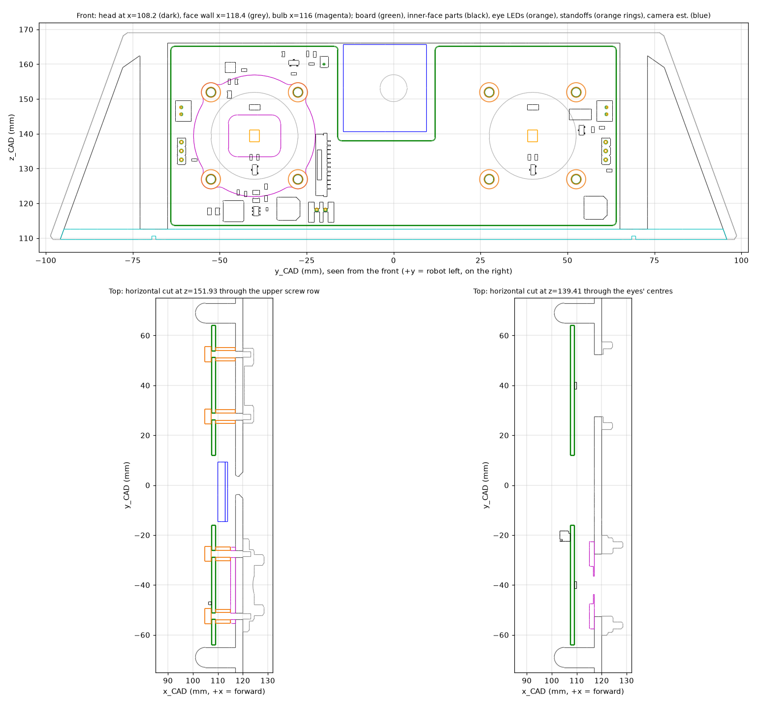
cad/parts.py loads the board's own STEP (fab/quack_face.step) and the
duck's print STLs (Open_Duck_Mini v2 @ b23317a, print/). It puts the board in the head's CAD
frame (outward face at x 109.0, inner face at x 107.4) and measures:
circles fitted to sections of head.stl, the eye parts and bulb.stl;
gaps and pilot depths, by rays cast through the meshes;
clearances, by closest points both ways between the meshes;
overlaps, by manifold3d booleans or a containment test;
the swept neck, from the research step's voxel cavity (neck over head_roll +-30 deg and
head_yaw +-160 deg, 1 mm voxels).
The camera is the spec's estimated outline, not a model.
Check
Measured
Board holes vs the face wall's holes (8)
every board hole 0.02 mm from the wall hole fitted to the STL (wall holes 2.698 mm, at z 126.91 / 151.91)
Board holes vs the eye parts' pilots
0.02 mm (left pilots 2.195 mm, right 2.045 mm, all blind, 3.0 mm deep)
Right-eye bulb ring holes
0.02 mm (2.698 mm)
Gap from the board's outward face to the bearing face
7.99 mm on the left eye (face wall, x 117.0), 5.99 mm on the right (bulb ring); the spacers are 8.0 and 6.0 mm
Screws
M2.5 x 16 pan head with two ISO 7089 washers (0.5 mm) under the head: grip 12.6 mm, 2.4 mm into the 3.0 mm blind pilot, 0.6 mm short of its bottom. Without washers no standard length fits: 14 mm engages 1.4 mm, 16 mm bottoms out
Screw heads + washers on the inner face (6.0 mm across, 2.75 mm tall)
1.625 mm from the nearest inner-face part
Board + parts vs head shell, floor, head-roll mount, speaker stand
min 0.99 mm (the bottom corner by the rib and the floor: the spec's 1 mm edge allowance); 0 points inside any of them
Spacers vs head, floor, roll mount, bulb ring
0.0 mm3 overlap (they bear on the wall and the bulb ring)
Board vs the swept neck (voxel cavity)
0 of 81 190 points in an occupied voxel; nearest occupied voxel 1 voxel (1 mm) away
Eye LEDs vs the 25.0 mm openings
0.0 mm off axis; LED face 7.21 mm from the wall's inner face; the opening subtends 60.0 deg half-angle (the LED's datasheet beam is 120 deg)
Right eye through the bulb ring
the ring's centre hole (radius 3.625 mm at x 116.75) cuts the cone to 27.5 deg half-angle (see Check these)
Eye parts
10.19 mm (left) and 9.24 mm (right) from the board and its parts; the bulb ring 5.91 mm
Camera (estimated outline)
1.7 mm from the notch; lens axis 12.03 mm from the nearest board edge (lens hole 7.75 mm, z 153.11)
Projector (flash_light_module)
16.65 mm
Mic port
at (y -20.0, z 160.0); 7.99 mm from the board's outward face to the wall, so the printed boot is 8.0 mm; the stock head.stl has no hole there
Room behind the tall inner-face parts (walking -x through the cavity)
J12 42.5 mm, J13 39.5, J14 39.5, J15 92.5, J16 90.5, J17 65.5, C1 44.5, C8 91.5, L1 more than 120
More previews: cad/img/fit_front_ghost.png (the head see-through, from the front) and
cad/img/fit_cut_z151.png (a cut through the upper screw row, from above). The KiCad renders
of both faces are in img/.
Printed parts (cad/print/, STEP and STL): standoff_left_8mm (4 off) and
standoff_right_6mm (4 off), both 5.5 mm across with a 2.9 mm bore and 0.3 mm chamfers. Also
mic_boot_8mm (4.6 mm across, 1.6 mm bore), only with a reprinted head. All three are
watertight meshes. cad/quack_face_in_head.step is the board's STEP with the
eight spacers, the boot and the two LED bodies, in the duck's CAD frame.
Silkscreen
Outward face: the three title lines centred under the camera notch, and L and R beside the
eye LEDs (robot left and right), and the LED footprints' own silk outlines.
Inner face: J12 CORE, J13 VBAT, PROJ, SPK, ANT L, ANT R and MIC beside their parts, and the
remaining designators. The brief's + mark for J13 pin 1 did not land (the known silk gap:
every spot the stage tries overlaps the XH pads). The footprint's own pin-1 mark is there.
Check these before ordering
The board passes ERC, the netlist round trip, routing, DRC (errors, unconnected and parity), DFM
and the fab gate in KiCad, and the CAD fit above. It has not been fabricated, assembled, powered
or fitted.
The interface
J13's pin order is this board's reading of the contract. The contract says "VBAT + GND,
JST-XH 2P" and nothing about pin numbers. Quack Face has pin 1 VBAT, pin 2 GND; the Quack
Core's J13 must match. A reversed harness reverses the 220 uF and the buck: there is no
reverse-polarity element here.
J12's harness must join pin n to pin n. Pre-crimped JST-GH cables come both straight and
reversed. J12 here is a top-entry (vertical) GH; the brain's J12 may be right-angle. The
mating parts are the same either way.
The microphone needs software: the runtime only reserves it (duck_config.py), so it
needs a full-duplex I2S overlay. The datasheet warns against clocking WS/SCK while VDD is off;
both boards share the Quack Core's switched supply.
The eyes
The two eyes will not look the same with the bulb ring in. The stock right eye keeps the
bulb ring between the wall and the board, which is why the brief uses 6 mm spacers there.
Its centre hole (radius 3.6 mm) now limits that LED to a 27.5 deg cone. The left eye sees the
whole 25 mm opening (60 deg). For symmetric eyes, leave the ring out and fit 8 mm spacers on
the right too (STANDOFF_RIGHT in cad/parts.py; the face wall's inner face measures x 117.0
on both sides, where the left eye's gap is 7.99 mm), or reprint the ring with a larger hole.
LED polarity. The XL-2835UWC-05 datasheet's recommended land puts its wide pad under pin 1,
the cathode, as KiCad's LED_PLCC_2835 does (pad 1 is the 2.2 mm pad). Its bottom-view
drawing shows the wide pad on the other side. Check one part against the board before reflow.
Brightness and heat are the 33 ohm resistors (estimated 48-67 mA, at most 0.15 W in each
0.25 W 1206). 22 ohm roughly doubles the light. Stay under the LED's 150 mA. The head is PLA.
No LED or amplifier body in the 3D outputs. KiCad 10.0.6 has no 3D model for
LED_PLCC_2835 or for the MAX98357A's TQFN-16 footprint, so the renders and
fab/quack_face.step have no body for D1, D2 or U3. The CAD fit adds the LEDs' datasheet
outline (3.5 x 2.8 x 0.79 mm).
Power
Buck loop with the bulk capacitor. TI's stability range is for ceramic output capacitors
(L x COUT 93-334 uH x uF for 5 V; 4.7 uH x about 22.8 uF effective = 107). The 220 uF
electrolytic on 5 V (360 mOhm at 100 kHz) sits at the left servo header, about 110 mm away.
Check the step response on the bench.
Inductor rating. The SWPA6045S4R7MT's catalogue row lists 3.3 A and 5.5 A without naming
which is the saturation and which the heating current. The buck's high-side limit is
3.9-5.4 A (TI).
Peak load (research spec 4.4, estimated): amplifier 0.8 A, two stalled servos 1.7 A, LEDs.
It is at the buck's 3 A. 5 V runs on 0.5 mm tracks and the In2 pour.
Amplifier heat. The MAX98357A's exposed pad has no via under it: the pipeline's
via-in-pad option would also drill the LED, inductor and electrolytic pads. At 3.2 W and
92 % efficiency (catalogue row) that is about 0.28 W in the package.
The projector current (about 160-200 mA, 0.26-0.4 W in its 1 W resistor) assumes a
3.0-3.4 V emitter. Measure the duck's emitter, or change R15.
Servo signal. 3.3 V PWM through 220 ohm; MG90S-class servos usually accept it, but the
duck's exact servo was not checked.
Mechanics
The board edge is 1 mm from the head's ribs, floor and ceiling (measured 0.99 mm). Put it
in square.
Screws: M2.5 x 16 pan head plus two M2.5 washers per hole (8 sets). The eye parts' pilots
are blind and 3.0 mm deep. The stock screws engage them no deeper, but do not overtighten.
The camera numbers rest on the spec's estimated outline (y -14.5..9.4, z 140.7..165.7, rear
parts to x 109.8). Check the real camera and its FFC against the notch.
The mic port needs a reprinted head with a 2 mm hole at CAD (y -20.0, z 160.0). That is a
modification of an Apache-2.0 file: mark it as changed (see cad/NOTICE).
Stackup. The gerber job lists KiCad's default 4-layer stackup (35 um copper, 0.48 mm FR4
dielectrics, 1.6 mm). The fab's real stackup is chosen when ordering.
Sourcing
All 27 part numbers in fab/quack_face_bom.csv come from parts/lcsc_pinned.json: 12 parts
and 5 passives added on 2026-10-02 from live heypcb parts lookup rows, the rest pinned
earlier (2026-06-23 and 2026-09-30). The lowest stock: ICS-43434 (C5656610) 3 807, the 10 ohm
2512 (C47019) 5 030, the 30 ohm boot resistor (C2907026) 11 009. Stock and Basic/Extended class
go stale; re-check on jlcpcb.com before ordering.
Files
In this folder (committed):
board.json: the brief.
cad/parts.py: the printed parts, the fit and the previews.
cad/print/: the printed parts, STEP and STL.
cad/img/: the fit previews.
cad/NOTICE and cad/LICENSE-Open_Duck_Mini-Apache-2.0.txt: attribution and licence.
img/: KiCad's raytraced renders of both faces.
The blocks are blocks/quackface_*.json; the part rows are in parts/lcsc_pinned.json.
Under build/quack_face/ (regenerated, not committed):
report.json: the gate report.
quack_face.kicad_sch and quack_face.kicad_pcb.
fab/:
quack_face_gerbers.zip;
quack_face_bom.csv (28 rows, 47 parts);
quack_face_cpl_jlc.csv (42 SMD parts, D1 and D2 on the bottom);
quack_face_pos.csv;
quack_face_schematic.pdf;
quack_face.step.
cad/: fit.json, the printed parts, quack_face_in_head.step and the previews.
video/quack_face_design_process.mp4.
Reproduce
From the heypcb-kicad repository:
bash
./run.sh --board boards/quack_face              # every stage, with the renders and the video
./run.sh --board boards/quack_face --no-media   # stop before the 3D frames, renders and video
DUCK_CAD=<duck folder> python cad/source/parts.py   # a Python with CadQuery and trimesh
parts.py needs CadQuery, trimesh, manifold3d, VTK, matplotlib and scipy. It reads the duck's
STLs from the folder DUCK_CAD names (default ./duck_cad): its cad/print/ is Open_Duck_Mini's
print/ at b23317a, and its fig/head_cavity.npz is the swept head cavity, which the research step
measured from those STLs and which is not shipped here.
Licence and attribution
Quack Face is a board for the Open Duck Mini. The duck is by Antoine Pirrone (apirrone) and
contributors (https://github.com/apirrone/Open_Duck_Mini), under the Apache License 2.0. The
board's outline, hole pattern, spacer lengths and the fit previews are derived from its CAD.
cad/NOTICE says what is derived and how, and cad/LICENSE-Open_Duck_Mini-Apache-2.0.txt is
the licence. No duck file is redistributed. The pin and port assignments follow the
Open_Duck_Mini_Runtime as interface facts; that repository has no licence file and none of its
code is copied here. The board uses no Disney or BD-X marks. KiCad's symbols and footprints are
CC-BY-SA-4.0 with the KiCad library exception.
License
Hardware: CERN-OHL-S v2. Files under cad/ that derive from third-party CAD carry their own notice there.
It measures 128 × 51.4 mm and has 4 copper layers, 1.6 mm thick.
What parts does the Quack face use?
55 parts, built around the MAX98357AETE+T, TPS56339DDC, ICS-43434 and XC6206P332MR-G. The full list of its parts is on this page, with links to each part's symbol and footprint where PCBKit's library has them.
Where can I download the Quack face KiCad files?
From the HeyPCB/quack-face repository on GitHub, at the commit this page was made from: the board is kicad/quack_face.kicad_pcb and its schematic kicad/quack_face.kicad_sch. PCBKit opens the board in the browser, with nothing to install.
Can I use the Quack face design in my own project?
Its repository publishes it under the CERN-OHL-S-2.0 licence: you may reuse it on that licence's terms (keep the author's notice, and for a copyleft licence share your changes alike).
Brain board for the Open Duck Mini: Pi Zero 2W carrier, 14-servo STS bus, fused 2S power path in stitched copper zones (15-18 A battery side), USB-C charging with balancing, IMU.
Iris Brainstem: power and servo hub of the Iris robot head. 9 V USB-C PD in, 6 V / 5 A servo rail in stitched copper zones (measured), 5 V rail, half-duplex servo bus with ten ports, speaker amp.