4 layers21 × 51 mm
Easyduino RP2040
Hanqaqa/Easyduino
Easily dive into different PCB KiCad designs of the most popular microcontroller devboards
65 parts755CERN-OHL-P-2.0
 Hanqaqa/Easyduino755
Easily dive into different PCB KiCad designs of the most popular microcontroller devboards
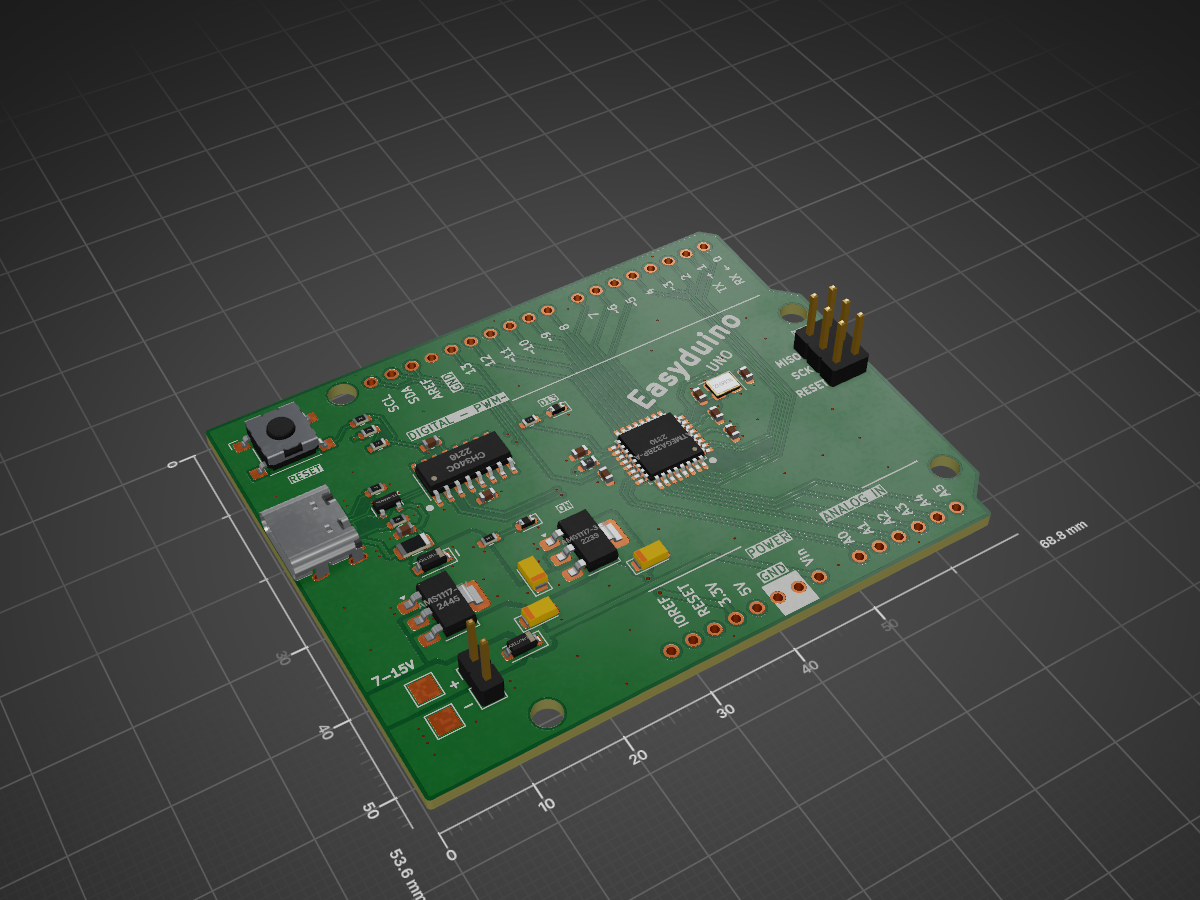
Easyduino Atmega is an open-source printed circuit board by Hanqaqa, from the Hanqaqa/Easyduino repository on GitHub, published under the CERN-OHL-P-2.0 licence. It is a 4-layer board of 68.8 × 53.6 mm with 38 parts on 55 nets, routed with 391 tracks and 106 vias.
It is built around the ATMEGA328P-AU, CH340C and AMS1117-3.3V, with the AMS1117-5V and PRTR5V0U2X among its other parts. Its parts include 12 capacitors, 7 resistors, 5 diodes, 4 ICs and 3 connectors. It belongs with the microcontroller boards boards and the ESP32, RP2040, STM32 and AVR (ATmega, ATtiny) boards of this library.


The most popular WiFi Microcontroller


KiCad Schematic symbols, footprints and 3D Models were obtained from their KiCad Github repository


| Qty | Value | Footprint | References |
|---|---|---|---|
| 7 | 100n | Capacitor_SMD:C_0603_1608Metric | C1, C2, C3, C4, C5, C6, C7 |
| 4 | 5.1k | Resistor_SMD:R_0603_1608Metric | R1, R2, R3, R4 |
| 3 | 22u | Capacitor_Tantalum_SMD:CP_EIA-3216-10_Kemet-I | C10, C11, C12 |
| 2 | 22p | Capacitor_SMD:C_0603_1608Metric | C8, C9 |
| 2 | 2k | Resistor_SMD:R_0603_1608Metric | R6, R7 |
| 2 | D_Schottky | Diode_SMD:D_SOD-123 | D2, D3 |
| 2 | LED | Diode_SMD:D_0603_1608Metric | D4, D5 |
| 2 | TestPoint | TestPoint:TestPoint_Pad_2.5x2.5mm | TP1, TP2 |
| 1 | 10uH | Inductor_SMD:L_0603_1608Metric | L1 |
| 1 | 16MHz | Crystal:Crystal_SMD_3225-4Pin_3.2x2.5mm | Y1 |
| 1 | 330 | Resistor_SMD:R_0603_1608Metric | R5 |
| 1 | AMS1117-3.3V | Package_TO_SOT_SMD:SOT-223-3_TabPin2 | U4 |
| 1 | AMS1117-5V | Package_TO_SOT_SMD:SOT-223-3_TabPin2 | U3 |
| 1 | ATmega328P-A | Package_QFP:TQFP-32_7x7mm_P0.8mm | U2 |
| 1 | Arduino_UNO_Connects | Module:Arduino_UNO_R3_WithMountingHoles | A1 |
| 1 | CH340C | Package_SO:SOIC-16_3.9x9.9mm_P1.27mm | U1 |
| 1 | Conn_01x02_Pin | Connector_PinHeader_2.54mm:PinHeader_1x02_P2.54mm_Vertical | J2 |
| 1 | ICSP | Connector_PinHeader_2.54mm:PinHeader_2x03_P2.54mm_Vertical | J3 |
| 1 | PRTR5V0U2X | Package_TO_SOT_SMD:SOT-143 | D1 |
| 1 | Polyfuse | Fuse:Fuse_1206_3216Metric | F1 |
| 1 | SW_Push | Button_Switch_SMD:SW_SPST_Omron_B3FS-100xP | SW1 |
| 1 | USB_C_Receptacle_USB2.0 | Connector_USB:USB_C_Receptacle_G-Switch_GT-USB-7010ASV | J1 |
It measures 68.8 × 53.6 mm and has 4 copper layers, 1.6 mm thick.
38 parts, built around the ATMEGA328P-AU, CH340C, AMS1117-3.3V and AMS1117-5V. The full list of its parts is on this page, with links to each part's symbol and footprint where PCBKit's library has them.
From the Hanqaqa/Easyduino repository on GitHub, at the commit this page was made from: the board is Atmega328p Arduino Uno/Easyduino_Atmega.kicad_pcb and its schematic Atmega328p Arduino Nano/Easyduino_Atmega_Nano.kicad_sch. PCBKit opens the board in the browser, with nothing to install.
Its repository publishes it under the CERN-OHL-P-2.0 licence: you may reuse it on that licence's terms (keep the author's notice, and for a copyleft licence share your changes alike).
Hanqaqa/Easyduino
Easily dive into different PCB KiCad designs of the most popular microcontroller devboards

Hanqaqa/Easyduino
Easily dive into different PCB KiCad designs of the most popular microcontroller devboards

Hanqaqa/Easyduino
Easily dive into different PCB KiCad designs of the most popular microcontroller devboards

Hanqaqa/Easyduino
Easily dive into different PCB KiCad designs of the most popular microcontroller devboards

Hanqaqa/Easyduino
Easily dive into different PCB KiCad designs of the most popular microcontroller devboards


jbteja/tj01-ms51-heater-controller
A heater control system featuring deterministic operation, safety auto-cutoff, predefined timer modes, and temperature measurement using a K-type thermocouple.


