
2 layers20 × 65 mm
019-tayloe quadrature product detector
Halogenek/modular-rf-bench
Cheap and simple setup for learning RF electronics
30 parts3
Cheap and simple setup for learning RF electronics
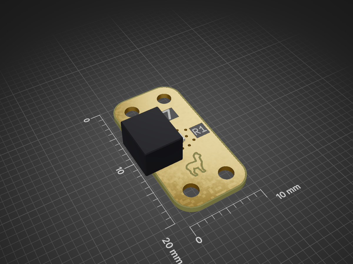
Load is an open-source printed circuit board by Halogenek, from the Halogenek/modular-rf-bench repository on GitHub. It is a 2-layer board of 10 × 20 mm with 7 parts on 2 nets, routed with 1 track and 13 vias.
Its parts include 1 resistor and 1 connector. It belongs with the radio and wireless boards of this library.
I came across an awesome system for rapid prototyping RF and Microwave solutions
by connecting individual components on small PCBs, just like LEGO.
This Modular building block system for RF and microwave design of prototypes is in my opinion a very clever way of building RF
circuits. On their website the sell almost every
available modern RF IC or passive network in a form of a rectangle PCBs.
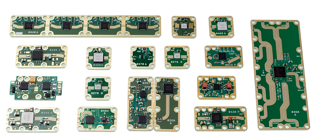
The whole system is well polished and every part has some sort of improvement. For example the boards interconnection has a ground cutout, probably for better impedance matching. The connection is done (according to their patent) with a small piece with diamond particles that improve contact. That's why they claim that this system can be used up to ~67 GHz.
Of course this performance comes at a price.
I liked this idea so much that I wanted to check how bad will standard FR4 boards perform if someone would make a system like this one. But without all those whistles.
So I made ten different designs inspired by that system. Ordered it on PcbWay.
And when will it arrive I will test it with my VNA.
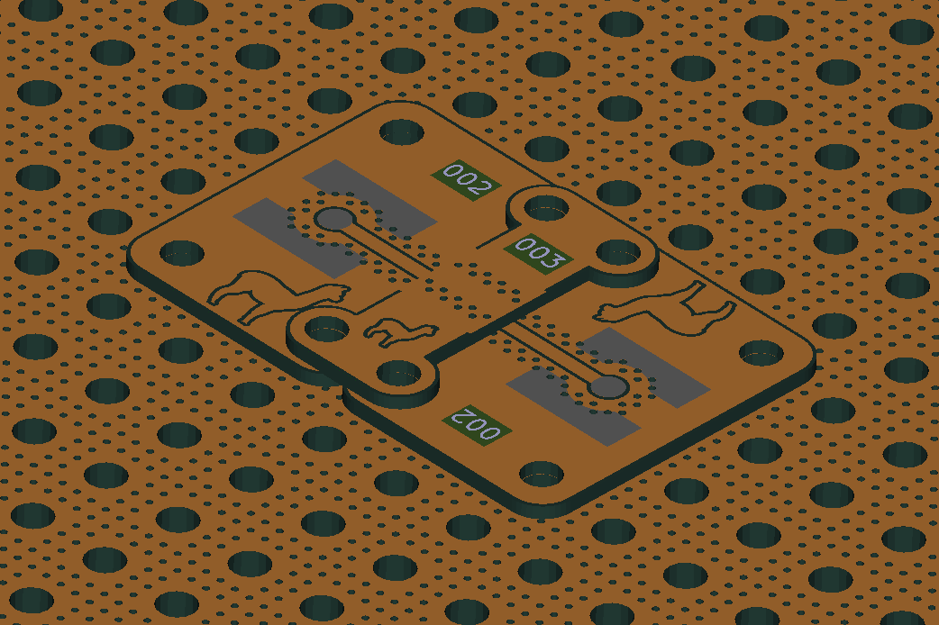
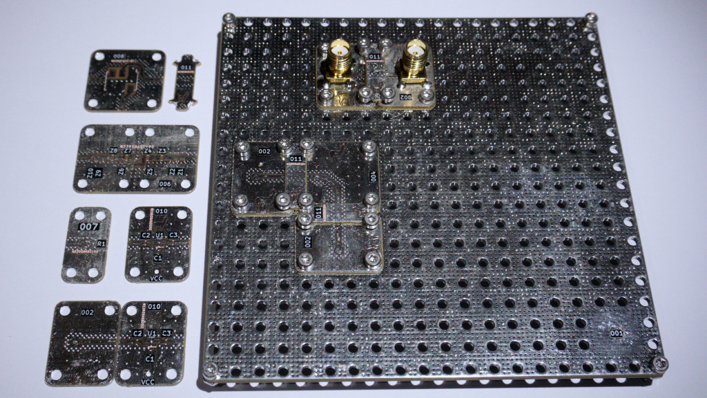
After some time the boards arrived in decent quality. I soldered SMA connectors to two boards designed for them and screwed them to the PCB base, together with a small interconnecting PCB.
I tried to follow X Microwave design but my idea had some problems. The small board with the number 011 that was designed to connect other boards didn't make good contact after mounted with screws. It just bulged up and the center signal trace didn't touched the traces on the other PCBs. But after adding a small amount of solder to the trace it started to work.
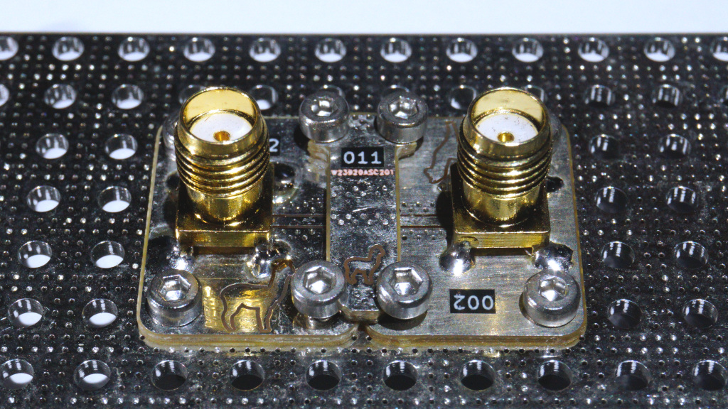
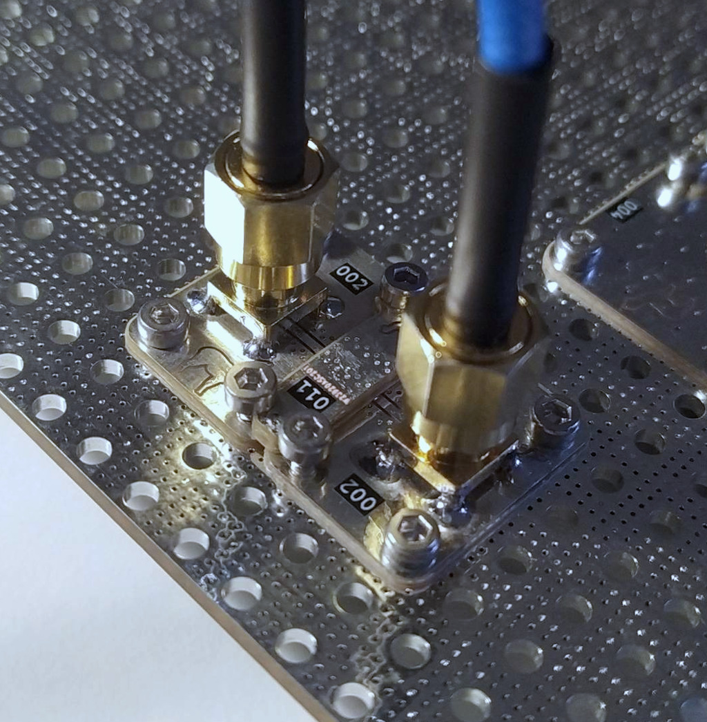
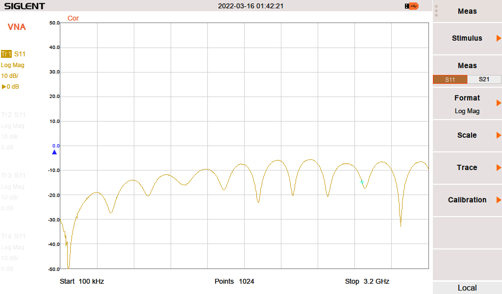
S11 50 Ohm termination
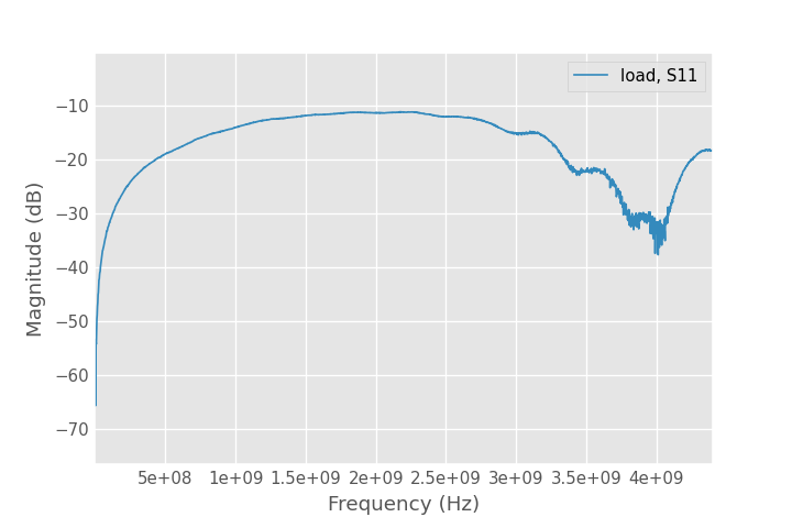 S11 50 Ohm termination by Port 2 of nanoVNA
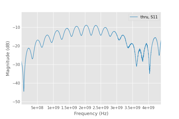
S11 50 Ohm termination
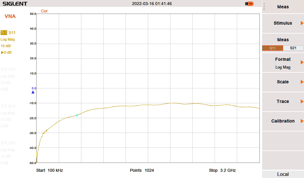 S11 50 Ohm termination by Port 2 of VNA
 S21
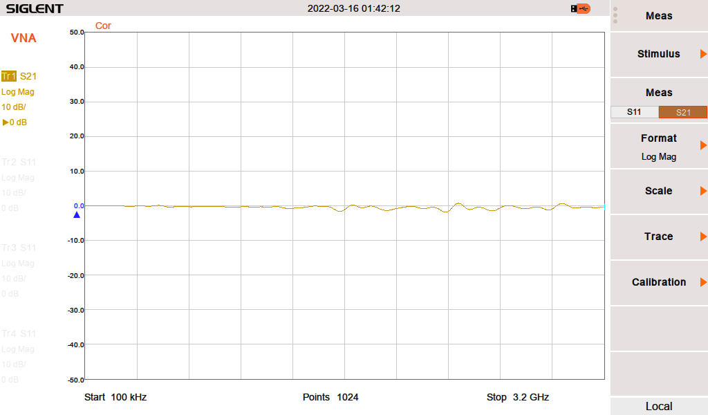
I wasn't excepting much after 0,8 mm FR4 PCB but it is usable up to 1,5 GHz. The board to board connection is working and everything is pretty durable.
| Qty | Value | Footprint | References |
|---|---|---|---|
| 4 | M2 | modular-rf-bench-footprints:M2-hole | H1, H2, H3, H4 |
| 1 | CONN | modular-rf-bench-footprints:edge-connector | J1 |
| 1 | LOGO | LOGO | G*** |
| 1 | R | Resistor_SMD:R_0805_2012Metric | R1 |
It measures 10 × 20 mm and has 2 copper layers, 0.8 mm thick.
7 parts. The full list of its parts is on this page, with links to each part's symbol and footprint where PCBKit's library has them.
From the Halogenek/modular-rf-bench repository on GitHub, at the commit this page was made from: the board is src/007-load/load.kicad_pcb and its schematic src/001-base/base.kicad_sch. PCBKit opens the board in the browser, with nothing to install.
Its repository states no licence, so its author keeps all rights: ask Halogenek before reusing the design.
Halogenek/modular-rf-bench
Cheap and simple setup for learning RF electronics


Halogenek/modular-rf-bench
Cheap and simple setup for learning RF electronics

Halogenek/modular-rf-bench
Cheap and simple setup for learning RF electronics


Halogenek/modular-rf-bench
Cheap and simple setup for learning RF electronics

Halogenek/modular-rf-bench
Cheap and simple setup for learning RF electronics


byrantech/laptop
anyon_e, a highly integrated, high end, open source laptop. Attempt the impossible.


AxxAxx/AxxSolder
STM32 Based soldering station for JBC cartridges, 9-24 VDC and USB-PD power


jamro/tiny-engineer
A small desktop robot that brings an AI coding assistant to life, physically acting out when it reads files, thinks, writes code, and finishes work.

hoglet67/RGBtoHDMI
Bare-metal Raspberry Pi project that provides pixel-perfect sampling of Retro Computer RGB/YUV video and conversion to HDMI
