2 layers227.8 × 48 mm

 Hackuarium/ion-mobility11
DIY Ion mobility spectrometer
Alim and ctr is an open-source printed circuit board by Hackuarium, from the Hackuarium/ion-mobility repository on GitHub. It is a 2-layer board of 208 × 130 mm with 72 parts on 47 nets, routed with 141 tracks and 28 vias.
It is built around the RHV2-1212S/R20, LM358 and LM358P, with the 6N137A, CNY65AYST and SSM3J340R,LF among its other parts. Its parts include 16 resistors, 13 capacitors, 12 connectors, 6 ICs and 4 transistors.


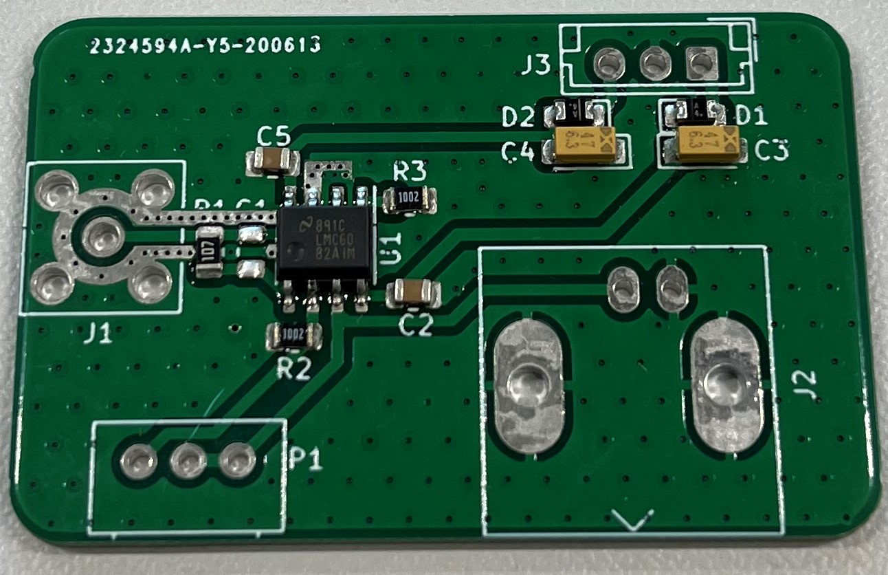
Amplification stage to transform the small current on the target to an acceptable voltage to be read/processed.
Transimpedance circuit with a big gain (10^8) and a voltage follower through a dual precision operationnal amplifier (Texas Instruments LMC6082).
The circuit needs to be as close as possible to the target of the IMS in order to limit the noise present on the signal. One possibility is to solder the PCB directly on the back of the target.
Possible amplification of the noise must be taken into account, and possibly filtered through a very small capacitor (~0.01 pF, thus quite expensive) in the gain stage feedback loop (a bigger resistor amplifies the signal but also the noise).
Below is a picture of the mounted PCB, currently missing the connectors and a potential filtering capacitor C1.
| Qty | Value | Footprint | References |
|---|---|---|---|
| 6 | TestPoint | TestPoint:TestPoint_Keystone_5000-5004_Miniature | TP2, TP4, TP5, TP6, TP7, TP8 |
| 3 | 100nF | Capacitor_SMD:C_0805_2012Metric | C6, C8, C12 |
| 3 | 20K | Resistor_SMD:R_0805_2012Metric | R8, R15, R16 |
| 2 | 1.5M | Resistor_SMD:R_1206_3216Metric | R2, R3 |
| 2 | 100R | Resistor_SMD:R_0805_2012Metric | R10, R11 |
| 2 | 1M | Resistor_SMD:R_0805_2012Metric | R4, R14 |
| 2 | 4700pF 10kV | Capacitor_THT:C_Rect_L13.0mm_W8.0mm_P10.00mm_FKS3_FKP3_MKS4 | C1, C2 |
| 2 | 50K | Potentiometer_THT:Potentiometer_Alps_RK097_Single_Horizontal | POT3, POT4 |
| 2 | HV out | Connector:conn_HV_JACK_PB1021 | J3, J4 |
| 1 | 0.22uF | Capacitor_THT:C_Rect_L13.0mm_W8.0mm_P10.00mm_FKS3_FKP3_MKS4 | C3 |
| 1 | 0.33uF Tant. | Capacitor_Tantalum_SMD:CP_EIA-3528-21_Kemet-B_Pad1.50x2.35mm_HandSolder | C10 |
| 1 | 100uF | Capacitor_THT:CP_Radial_D5.0mm_P2.50mm | C11 |
| 1 | 10M | Resistor_SMD:R_1206_3216Metric | R5 |
| 1 | 10M | Potentiometer_THT:Potentiometer_Vishay_148-149_Single_Vertical | POT1 |
| 1 | 12V in | Connector_PinHeader_2.54mm:PinHeader_2x01_P2.54mm_Vertical | J7 |
| 1 | 15A | HV_source:15A | HV2 |
| 1 | 15pF | Capacitor_SMD:C_0805_2012Metric | C7 |
| 1 | 1K | Resistor_SMD:R_1206_3216Metric | R9 |
| 1 | 2,2uF | Capacitor_SMD:C_0805_2012Metric_Pad1.15x1.40mm_HandSolder | C13 |
| 1 | 2,2uF | Capacitor_THT:CP_Radial_D5.0mm_P2.50mm | C9 |
| 1 | 2500pF 15 kV | Capacitor_THT:C_Rect_L19.0mm_W8.0mm_P15.00mm_MKS4 | C4 |
| 1 | 3.3M | Resistor_SMD:R_0805_2012Metric | R13 |
| 1 | 47uF/100V | Capacitor_THT:CP_Radial_D12.5mm_P5.00mm | C5 |
| 1 | 500K | Resistor_THT:R_Axial_DIN0204_L3.6mm_D1.6mm_P7.62mm_Horizontal | R1 |
| 1 | 50R | Resistor_SMD:R_1206_3216Metric | R7 |
| 1 | 5K | Resistor_SMD:R_0805_2012Metric_Pad1.15x1.40mm_HandSolder | R6 |
| 1 | 6N137A | Package_DIP:DIP-8_W7.62mm_Socket | U1 |
| 1 | Ap Grid | Connector:conn_HV_JACK_PB1021 | J8 |
| 1 | CNY65AYST | OptoDevice:CNY65AYST | OPTO1 |
| 1 | EN switch | Connector_PinHeader_2.54mm:PinHeader_2x01_P2.54mm_Vertical | SW1 |
| 1 | Electrode in | Connector:conn_HV_JACK_PB1021 | J1 |
| 1 | Electrode out | Connector:conn_HV_JACK_PB1021 | J2 |
| 1 | G40 | HV_source:G40 | HV1 |
| 1 | Gate | Connector:conn_HV_JACK_PB1021 | J6 |
| 1 | HV1 Switch | Connector_PinHeader_2.54mm:PinHeader_2x01_P2.54mm_Vertical | SW2 |
| 1 | Jumper | Connector_PinHeader_1.00mm:PinHeader_1x02_P1.00mm_Horizontal | JP1 |
| 1 | LCD1 PWR | Connector_JST:JST_EH_B2B-EH-A_1x02_P2.50mm_Vertical | J12 |
| 1 | LCD1 V/I measures | Connector_JST:JST_EH_B3B-EH-A_1x03_P2.50mm_Vertical | J11 |
| 1 | LCD2 PWR | Connector_JST:JST_EH_B2B-EH-A_1x02_P2.50mm_Vertical | J10 |
| 1 | LCD2 Vin | Connector_JST:JST_EH_B2B-EH-A_1x02_P2.50mm_Vertical | J9 |
| 1 | LM358 | Package_DIP:DIP-8_W7.62mm_Socket | U3 |
| 1 | LM358P | Package_DIP:DIP-8_W7.62mm_Socket | U6 |
| 1 | Last Electrode | Connector:conn_HV_JACK_PB1021 | J5 |
| 1 | Lolin32 | Dev_boards:Lolin32 | U4 |
| 1 | MC78M15ACTG | Package_TO_SOT_THT:TO-262-3_Vertical | U5 |
| 1 | Mid electrode1 | Connector:conn_HV_JACK_PB1021 | E1 |
| 1 | Mid electrode2 | Connector:conn_HV_JACK_PB1021 | E2 |
| 1 | PWR LED | LED_THT:LED_D4.0mm | D1 |
| 1 | PWR switch | Connector_PinHeader_2.54mm:PinHeader_2x01_P2.54mm_Vertical | SW3 |
| 1 | RHV2-1212S/R20 | Isolated_converters:R8 | PS1 |
| 1 | RHV2-1212S/R20 | Isolated_converters:R20 | PS2 |
| 1 | R_LED | Resistor_SMD:R_0805_2012Metric | R12 |
| 1 | SSM3J340R | Package_TO_SOT_SMD:SOT-23_Handsoldering | Q3 |
| 1 | ZTX1053A | Package_TO_SOT_SMD:SOT-23_Handsoldering | Q4 |
| 1 | ZTX1053A | Package_TO_SOT_THT:TO-220-3_Vertical | Q2 |
| 1 | ZVN2110A | Package_TO_SOT_THT:TO-220-3_Vertical | Q1 |
| 1 | mEZD41501A-X | Connector_JST:JST_EH_B6B-EH-A_1x06_P2.50mm_Vertical | U2 |


FinnKrass/MX-Break-In-Machine
64 Slot Break In Machine for MX Style Switches


Lafayette-Motorsports/LVBoards
LV Board repository for Motorsports created 09.02.2025

abdontroche/InfraRed_Gel_Universal_Dispenser
This project pretends to be a open source device that could help people fighting against the COVID-19.

igorzab-stud/wanptek_encoder
Digital front-panel mod for Wanptek DC power supplies — replaces analog potentiometers with dual rotary encoders, MCP4725 DACs, and an OLED display.

ansh1113/e-bike-conversion-kit
A 4-layer PCB-based e-bike conversion kit featuring an STM32-based VESC ESC, power management circuits, wireless throttle, GSM, GPS, and more.


UAA-F14/PCBs-Design
Power electronics PCB coursework — SCR controller, buck converter, Class D amplifier, DC-AC inverter, and a protected power supply Resources
It measures 208 × 130 mm and has 2 copper layers, 1.6 mm thick.
72 parts, built around the RHV2-1212S/R20, LM358, LM358P and 6N137A. The full list of its parts is on this page, with links to each part's symbol and footprint where PCBKit's library has them.
From the Hackuarium/ion-mobility repository on GitHub, at the commit this page was made from: the board is PCB/Divider/Complete_divider/Alim_and_ctr.kicad_pcb. PCBKit opens the board in the browser, with nothing to install.
Its repository states no licence, so its author keeps all rights: ask Hackuarium before reusing the design.