4 layers45 × 75.9 mm
 h0lad/SolarMeshtasticNode40
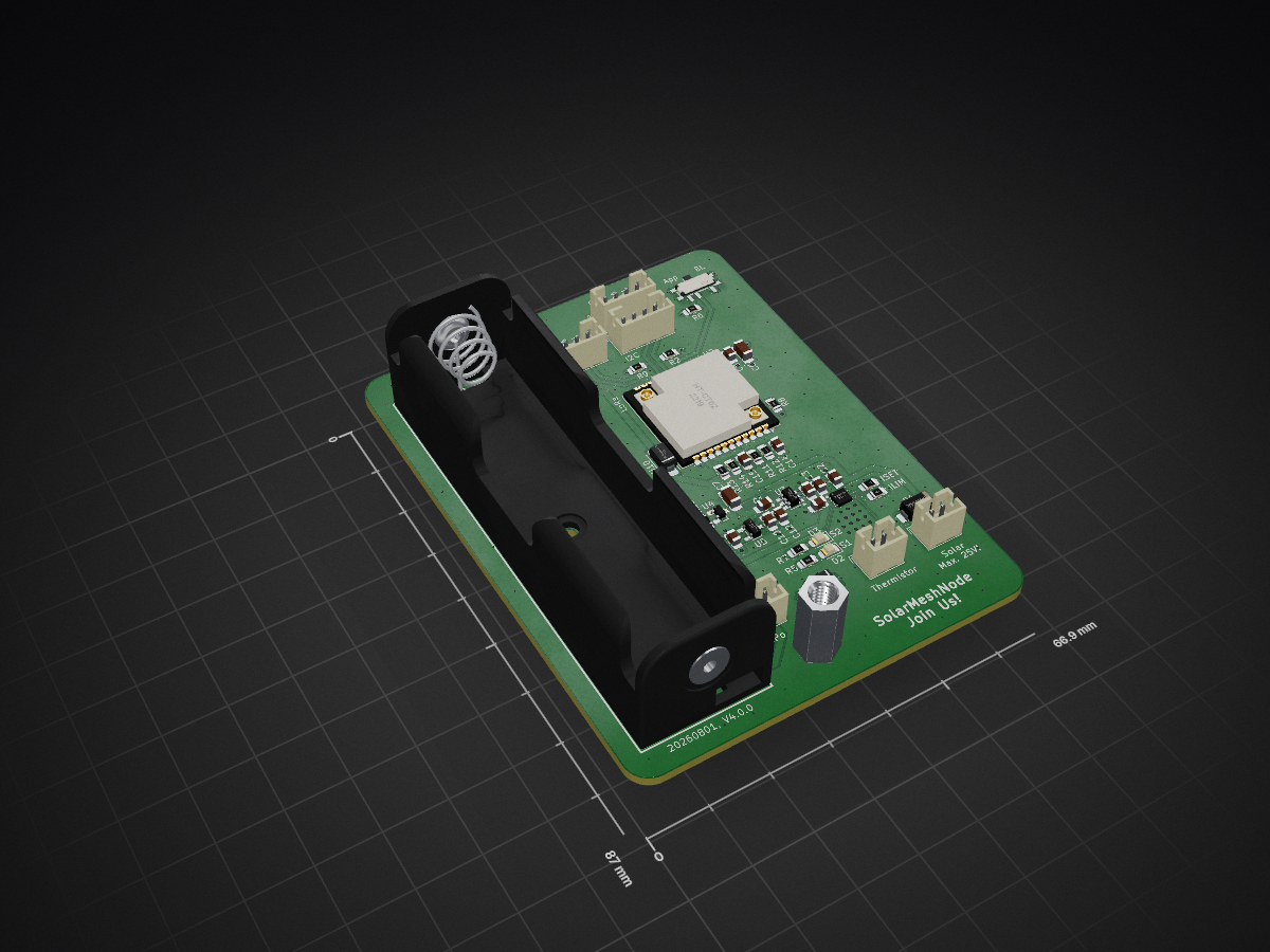
This is a Meshtastic Solar Node PCB based on the Heltec HT-CT62 and the linear solar charge controller TI BQ25185.
MeshtasticNode BQ25185 is an open-source printed circuit board by h0lad, from the h0lad/SolarMeshtasticNode repository on GitHub, published under the CERN-OHL-S-2.0 licence. It is a 4-layer board of 66.9 × 87 mm with 49 parts on 36 nets, routed with 195 tracks and 237 vias.
It is built around the HE9073A30MR, TPS22917DBV and BH-18650-A1AJ005, with the SMAJ14A and SSSS811101 among its other parts. Its parts include 14 capacitors, 14 resistors, 6 ICs, 6 connectors and 3 diodes. It belongs with the power and radio and wireless boards and the ESP32 boards of this library.


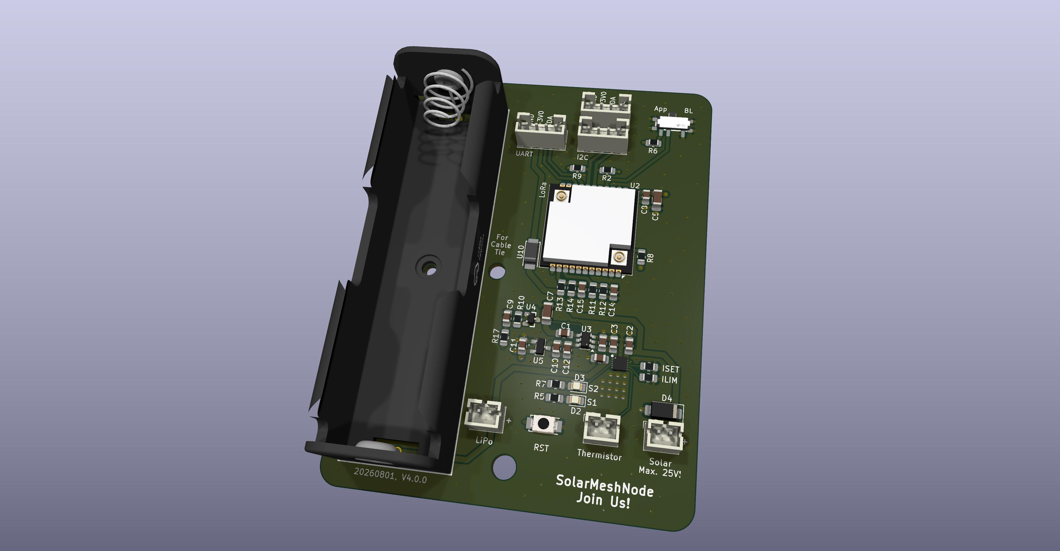
This is a Meshtastic solar node based on the Heltec HT-CT62 and the (new) linear solar charge controller TI BQ25185.
Features of this PCB
Combined with a solar panel this device can be placed in remote areas to cover a wide range.
| Pin | GPIO | Description |
|---|---|---|
| 8 | GPIO2 | Boot strapping pin (R8 10kΩ pull-up to +3V0) |
| 9 | GPIO1 | ADC_VLOAD - load voltage measurement (1:2 divider via R11, R12, C14) |
| 10 | GPIO0 | ADC_VBUS - solar panel voltage measurement (~1:10 divider via R13, R14, C15) |
| 15 | GPIO9 | Bootloader mode switch (SW1 via R6 1kΩ to +3V0) |
| 16 | GPIO8 | Boot strapping pin (R1 10kΩ pull-up to +3V0) |
| 17 | GPIO18 | I2C SCL (J5, J7 JST-PH 1x4, R2 10kΩ pull-up) |
| 18 | GPIO19 | I2C SDA (J5, J7 JST-PH 1x4, R9 10kΩ pull-up) |
| 19 | GPIO20 | UART RX (J4 JST-PH 1x4) |
| 20 | GPIO21 | UART TX (J4 JST-PH 1x4) |
RST is not routed through a HT-CT62 pin. Reset is performed by the APX803L05 brown-out IC (U4) and push button (SW4) pulling the TPS22917 load switch ON pin low cutting the 3.0V rail to the module.
Info
The successor of this project is now in its very early development stages: LoRaPowerBox.
There is also a miniaturized version of this PCB: SolarMeshtasticNodeMini.
The size of the PCB is 66.85 mm x 87mm and is planned around following Box (120x90x70).
Heltec HT-CT62: Aliexpress
TI BQ25185: Mouser or Digikey
PCB: You can load the Kicad project file and then export the manufacturing files using the plugins. Just throw them into JLCPCB and order them.
Everything else can be ordered from LCSC.
Due to strict legislation, it is not planned to offer ready-made circuit boards or kits here. Sorry.
Warning 1
By enabling "Power Saving" you will loose all regular telemetry (Sensors, Battery Voltages, etc.)! The battery voltage can be polled manually using the Python lib.
I reported this a bug but it was rejected.
Warning 2
You also will not be able to configure it by serial port anymore! You have a short period after power cycling it. Use the "meshtastic" Python script as it waits for a while.
Enable "Power Saving" (is activated by default if using Router role)
When configuring the device you should set the "Minimum Wake Interval" from 10 seconds to 1 second.
Switch Bluetooth and Wifi off! They suck power like crazy.
This is more tricky as per default it doesn't switch into "Light Sleep" as several delays are blocking it.
You also have to decrease "Wait Bluetooth Seconds" and "Screen on Seconds" to 1 second.
Then configure is like a "Router".
I'm keeping a more or less outdated branch von the Meshtastic firmware on git@github.com:dm5tt/meshtastic-firmware.git in the branch solarmeshtasticnode. If you want a fresher version you must rebase it yourself.
Evaluation, PCB v2.0.0 (18650)
The HT-CT62 uses a ESP32C3. Thats not Low Power!!!
Meshtastic supports the "Power Saving" mode on the ESP32 where the entire device stays in the light sleep mode until it gets a interrupt signal from the LoRa modem. In that phase CPU will consume around ~800uA while sleeping.
Permanent active LoRa RX from the Semtech modem will always cause a consumption of 7-8mA. Not even a STM32 or Nordic can get rid of this.
Much less power consumption could be achieved in a sensor scenario where permanent RX is not required: there the worst-case is most likely determined by the current draw of the sleeping microcontroller and component leakage.
Warning, again: switching on BLE or even Wifi will make the ESP32 burn a crazy amount of energy.
For sunny regions (Portugal, Spain, etc.) a 6V panel is enough. For central Europe (like Germany) a 12V or higher solar panel is recommended for surviving the winter.
It's not really that cheap either!
Yep. It's expensive if you build only 1 device. But the costs dramatically drop if think of building 5-10 of them as you can mass order everything (PCBs, Components from LCSC and so own).
The TI BQ25185 uses a linear regulator to create the voltage before the LDO. That will be inefficient for solar panels above 6V.
Yes. It's very inefficient if it's running with the power path enabled (= direct solar pass-through) as the device has to burn off a lot of voltage from the panel. During battery runtime the difference is way lower which is acceptable.
It maybe cause unneccesary heat during the winter time where small 18V solar panels would be a great benefit. But for 6V panels it's a within acceptable ranges.
I'm planing to build a new generation of the SolarMeshtasticNode with the upcoming TI BQ25630. It has an integrated ADC (which allows us to get rid of all power dividers) and also has a very efficient DC DC buck architecture. Price wise it will be around $2 which is still very acceptable.
Why are you using a 3.0V and not a 3.3V LDO?
This gives us more runtime by only loosing 1-2dB TX power from the LoRa module.
With a 3.3V LDO the device will switch off around ~3.5V - with 3.0V LDO it can survive down to 3.2V.
LED circuit for STAT1 and STAT2 aren't tested. The TI BQ25185 uses 1.8V for the status pins so the LEDs must be switched via a transistor against the 3.3V supply voltage.
CERN OHL v2 – Strongly Reciprocal (S)
| Qty | Value | Footprint | References |
|---|---|---|---|
| 4 | 1uF | Capacitor_SMD:C_0805_2012Metric_Pad1.18x1.45mm_HandSolder | C2, C6, C12, C13 |
| 3 | 100nF | Capacitor_SMD:C_0805_2012Metric_Pad1.18x1.45mm_HandSolder | C8, C14, C15 |
| 3 | 10k | Resistor_SMD:R_0805_2012Metric_Pad1.20x1.40mm_HandSolder | R2, R8, R9 |
| 3 | 10uF | Capacitor_SMD:C_0805_2012Metric_Pad1.18x1.45mm_HandSolder | C3, C9, C10 |
| 3 | Conn_01x02_Socket | Connector_JST:JST_PH_B2B-PH-K_1x02_P2.00mm_Vertical | J1, J2, J8 |
| 3 | Conn_01x04_Socket | Connector_JST:JST_PH_B4B-PH-K_1x04_P2.00mm_Vertical | J4, J5, J7 |
| 2 | 1.2k | Resistor_SMD:R_0805_2012Metric_Pad1.20x1.40mm_HandSolder | R5, R7 |
| 2 | 100k | Resistor_SMD:R_0805_2012Metric_Pad1.20x1.40mm_HandSolder | R3, R10 |
| 2 | 1M | Resistor_SMD:R_0805_2012Metric_Pad1.20x1.40mm_HandSolder | R11, R12 |
| 2 | LED | LED_SMD:LED_0805_2012Metric_Pad1.15x1.40mm_HandSolder | D2, D3 |
| 1 | 100nF | Capacitor_SMD:C_1206_3216Metric_Pad1.33x1.80mm_HandSolder | C7 |
| 1 | 1k | Resistor_SMD:R_0805_2012Metric_Pad1.20x1.40mm_HandSolder | R6 |
| 1 | 1nF | Capacitor_SMD:C_0805_2012Metric_Pad1.18x1.45mm_HandSolder | C1 |
| 1 | 375 | Resistor_SMD:R_0805_2012Metric_Pad1.20x1.40mm_HandSolder | R4 |
| 1 | 4.7uF | Capacitor_SMD:C_0805_2012Metric_Pad1.18x1.45mm_HandSolder | C11 |
| 1 | 470 | Resistor_SMD:R_0805_2012Metric_Pad1.20x1.40mm_HandSolder | R17 |
| 1 | 47uF | Capacitor_SMD:C_1206_3216Metric_Pad1.33x1.80mm_HandSolder | C5 |
| 1 | 820k | Resistor_SMD:R_0805_2012Metric_Pad1.20x1.40mm_HandSolder | R13 |
| 1 | 91k | Resistor_SMD:R_0805_2012Metric_Pad1.20x1.40mm_HandSolder | R14 |
| 1 | APX803L05-32SA-7 | footprints:SOT23-3 | U4 |
| 1 | BH-18650-A1AJ005 | footprints:BAT-TH_BH-18650-A1AJ005 | BT1 |
| 1 | BQ25185 | footprints:SON40P220X200X80-11N | U1 |
| 1 | HE9073A30MR | footprints:SOT-23-3_L2.9-W1.6-P1.90-LS2.8-BR-CW | U5 |
| 1 | HT-CT62 | RF_Module:Heltec_HT-CT62 | U2 |
| 1 | MountingHole | MountingHole:MountingHole_2.2mm_M2 | H2 |
| 1 | MountingHole | MountingHole:MountingHole_3.2mm_M3_DIN965 | H1 |
| 1 | MountingHole | MountingHole:MountingHole_4.3mm_M4_DIN965 | H3 |
| 1 | SMAJ14A | Diode_SMD:D_SMA | D4 |
| 1 | SS26_C5350986 | footprints:SMA_L4.3-W2.6-LS5.1-RD | U10 |
| 1 | SSSS811101 | footprints:SW-SMD_SSSS811101 | SW1 |
| 1 | SW_Push | footprints:SMA_L4.3-W2.6-LS5.1-RD | SW4 |
| 1 | TPS22917DBV | Package_TO_SOT_SMD:SOT-23-6 | U3 |
It measures 66.9 × 87 mm and has 4 copper layers, 1.62 mm thick.
49 parts, built around the HE9073A30MR, TPS22917DBV, BH-18650-A1AJ005 and SMAJ14A. The full list of its parts is on this page, with links to each part's symbol and footprint where PCBKit's library has them.
From the h0lad/SolarMeshtasticNode repository on GitHub, at the commit this page was made from: the board is pcb/MeshtasticNode_BQ25185.kicad_pcb and its schematic pcb/MeshtasticNode_BQ25185.kicad_sch. PCBKit opens the board in the browser, with nothing to install.
Its repository publishes it under the CERN-OHL-S-2.0 licence: you may reuse it on that licence's terms (keep the author's notice, and for a copyleft licence share your changes alike).

h0lad/LoRaHarvesterBox
PCB integrating a ST STM32WLE5CC and TI BQ25570 energy harvester. Ideal platform for ultra-low-power LoRa(WAN) nodes projects.


axpaul/Avionic-Mastodonte
Mastodonte experimental rocket avionic (On-board electronics) created by Paul Miailhe, Version 2025

axpaul/Avionic-Sirius
Sirius experimental rocket avionic (On-board electronics) created by Paul Miailhe, Version 2023/2024 launched at C'space 2024


rekirxs/NeoXalle-PCB-Slave
A full PCB work for a sport sensorial reaction device called NeoXalle.