

2 layers62 × 208.5 mm
Combined
wr/airwriter
Print to vintage Apple printers from modern devices over AirPrint, or from a vintage Mac over AppleTalk.
154 parts7

 gjberger/pico2-starter
Bare-metal C on the Raspberry Pi Pico 2 (RISC-V), no SDK: linker script, minimal lib, UART loader
Pico2w usbc header board is an open-source printed circuit board by gjberger, from the gjberger/pico2-starter repository on GitHub. It is a 4-layer board of 31.5 × 76.5 mm with 44 parts on 73 nets, routed with 341 tracks and 70 vias.
It is built around the CP2102N-A02-GQFN24, SN74AHCT1G125DBVR(UMW) and USBLC6-2SC6, with the SK6812MINI-C and MBR120VLSFT1G-TP among its other parts. Its parts include 16 resistors, 12 capacitors, 9 diodes, 3 ICs and 3 connectors. It belongs with the interfaces and adapters boards and the RP2040 and RP2350 boards of this library.


Ari — this is the hardware design for Gabe’s Pico 2 W carrier. It adds USB-C power, a CP2102N USB-to-serial bridge, and six programmable LEDs.
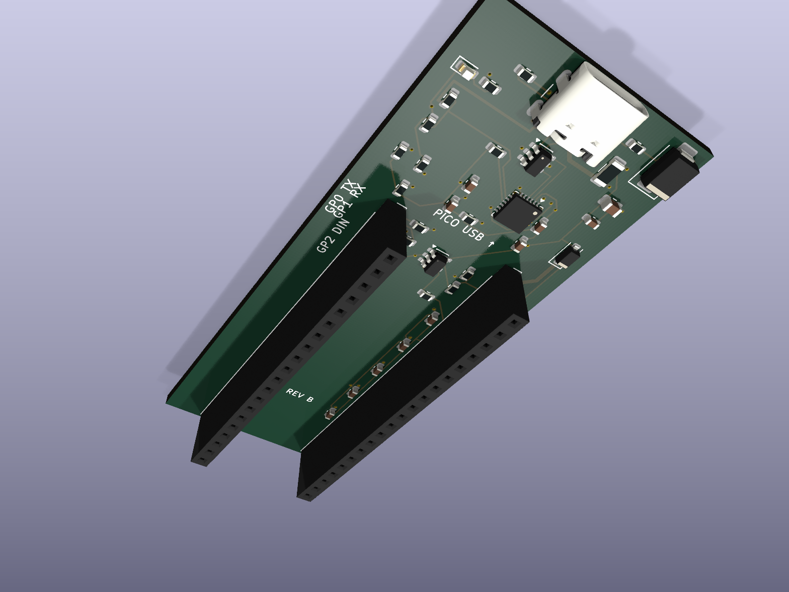
Download the repository ZIP using Code → Download ZIP, extract it, and open PCB files/pico2w-usbc-header-board.kicad_pro in KiCad 9. Keep the folder together: the schematic, routed board, and custom libraries are included. No generation scripts are needed.
Use the fabrication ZIP with the JLCPCB order instructions. The ZIP contains the manufacturing and assembly files; the instructions explain the upload settings.
The carrier’s USB-C connector supplies power and exposes UART0 through the CP2102N: Pico GP0 = TX, GP1 = RX. It does not expose the Pico’s native USB interface. Follow the starter instructions for the UART bootloader and loading programs. Initial UF2/BOOTSEL flashing uses the Pico’s own micro-USB port; subsequent UART loading uses the carrier once the bootloader is installed.
This carrier is documented for the Pico 2 W. The starter’s GPIO 25 blink example is written for the non-wireless Pico 2; do not use that blink as a Pico 2 W hardware check. The carrier’s external LED chain uses GP2 and needs addressable-LED signaling.
The source project reports a successful assembled-board power-up and UF2 run on July 22, 2026. USB serial, LED behavior, dual-USB power, and wireless performance still need recorded hardware validation. Bring-up checklist contains the detailed checks; its introductory wording predates the reported successful power-up.
The design notes recommend limiting LEDs to about 60% full-white brightness or less on a default 500 mA USB source.
These files come from the August 24, 2026 share bundle. Design and manufacturing files are unchanged.
| Qty | Value | Footprint | References |
|---|---|---|---|
| 9 | 100nF 16V X7R | Capacitor_SMD:C_0603_1608Metric | C2, C4, C5, C7, C8, C9, C10, C11, C12 |
| 6 | SK6812MINI-C | Pico2W_Carrier:SK6812MINI-C | D4, D5, D6, D7, D8, D9 |
| 5 | 100k | Resistor_SMD:R_0603_1608Metric | R9, R13, R14, R15, R16 |
| 2 | 1k | Resistor_SMD:R_0603_1608Metric | R5, R8 |
| 2 | 4.7k UART | Resistor_SMD:R_0603_1608Metric | R6, R7 |
| 2 | 4.7uF 10V X7R | Capacitor_SMD:C_0603_1608Metric | C3, C6 |
| 2 | 5.1k 1% | Resistor_SMD:R_0603_1608Metric | R1, R2 |
| 1 | 10k | Resistor_SMD:R_0603_1608Metric | R10 |
| 1 | 10uF 10V X7R | Capacitor_SMD:C_0805_2012Metric | C1 |
| 1 | 2.2k | Resistor_SMD:R_0603_1608Metric | R12 |
| 1 | 22.1k 1% | Resistor_SMD:R_0603_1608Metric | R3 |
| 1 | 47.5k 1% | Resistor_SMD:R_0603_1608Metric | R4 |
| 1 | 470 | Resistor_SMD:R_0603_1608Metric | R11 |
| 1 | 750mA resettable PTC | Fuse:Fuse_1206_3216Metric | F1 |
| 1 | CP2102N-A02-GQFN24 | Pico2W_Carrier:CP2102N-A02-GQFN24 | U1 |
| 1 | MBR120VLSFT1G | Diode_SMD:D_SOD-123F | D1 |
| 1 | POWER GREEN | LED_SMD:LED_0603_1608Metric | D3 |
| 1 | Pico 2W LEFT pins 1-20 | Connector_PinSocket_2.54mm:PinSocket_1x20_P2.54mm_Vertical | J2 |
| 1 | Pico 2W RIGHT pins 40-21 | Connector_PinSocket_2.54mm:PinSocket_1x20_P2.54mm_Vertical | J3 |
| 1 | SMBJ5.0A TVS | Diode_SMD:D_SMB | D2 |
| 1 | SN74AHCT1G125DBVR | Package_TO_SOT_SMD:SOT-23-5 | U3 |
| 1 | USB-C USB2 sink | Pico2W_Carrier:USB4105-GF-A | J1 |
| 1 | USBLC6-2SC6 | Package_TO_SOT_SMD:SOT-23-6 | U2 |
wr/airwriter
Print to vintage Apple printers from modern devices over AirPrint, or from a vintage Mac over AppleTalk.

Jubakuba/Volt-80-Kicad
This PCB can be purchased and assembled by JLCPCB or other services. You can have them assemble hotswap socket of your choice or order them and solder them yourself.

nspired-Hackers/nternet-Link
Wi-Fi, AI chat, and camera module for TI-Nspire calculators. Custom ESP32 PCBs + firmware. (Yes, 'nternet' is intentional, Nspire community naming.)

PCB-Design-MIT/Wi-Fi-Controlled-RGB-Light
A demo board for students to learn to solder and debug

bdini13/esp32-cc1101-multiband
Work-in-progress ESP32-WROOM-32E + CC1101 multiband PCB: software-selected 315/433/868/915 MHz paths. AI-assisted engineering draft; not manufacturing-ready.


durveshpathak1989/kicad-local-agent
Free local Ollama agent for generating and validating KiCad project files

kaorii-ako/Poket
ESP32-S3 Bluetooth MP3 player - custom PCB + 3D-printed case, built from scratch
It measures 31.5 × 76.5 mm and has 4 copper layers, 1.6 mm thick.
44 parts, built around the CP2102N-A02-GQFN24, SN74AHCT1G125DBVR(UMW), USBLC6-2SC6 and SK6812MINI-C. The full list of its parts is on this page, with links to each part's symbol and footprint where PCBKit's library has them.
From the gjberger/pico2-starter repository on GitHub, at the commit this page was made from: the board is PCB files/pico2w-usbc-header-board.kicad_pcb and its schematic PCB files/pico2w-usbc-header-board.kicad_sch. PCBKit opens the board in the browser, with nothing to install.
Its repository states no licence, so its author keeps all rights: ask gjberger before reusing the design.