
4 layers90 × 36 mm
A2-routing candidate
bdini13/esp32-cc1101-multiband
Work-in-progress ESP32-WROOM-32E + CC1101 multiband PCB: software-selected 315/433/868/915 MHz paths. AI-assisted engineering draft; not manufacturing-ready.
107 parts1

 bdini13/esp32-cc1101-multiband1
Work-in-progress ESP32-WROOM-32E + CC1101 multiband PCB: software-selected 315/433/868/915 MHz paths. AI-assisted engineering draft; not manufacturing-ready.
A3-before crystal refinement is an open-source printed circuit board by bdini13, from the bdini13/esp32-cc1101-multiband repository on GitHub. It is a 4-layer board of 90 × 36 mm with 121 parts on 107 nets, routed with 1,005 tracks and 172 vias.
It is built around the PE42442A-Z, CC1101RGPR and ESP32-WROOM-32E-N8, with the SN74LVC2G125DCTR-JSM, CP2102N-A02-GQFN24 and MMBT3904 among its other parts. Its parts include 43 capacitors, 23 resistors, 14 inductors, 8 ICs and 5 diodes. It belongs with the radio and wireless boards and the ESP32 boards of this library.


A custom USB-C development board combining an ESP32-WROOM-32E-N8 with an integrated CC1101 sub-GHz radio, software-selected RF paths, and a vertical SMA antenna connector at the opposite end from USB-C.
Rev A3 · Fully connected review candidate · Not approved to manufacture or sell
The aim is to replace a separate ESP32 board, CC1101 breakout and jumper wires with one purpose-built PCB. The first intended build is five assembled engineering prototypes, after the pre-order checks are complete. Possible product sales are a future option, not a launch announcement.
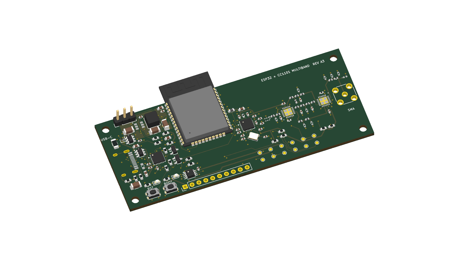
KiCad design render—not a photograph of a built board. USB, SMA and some RF parts lack complete 3D bodies. Their absence in the image does not mean they were removed from the design.
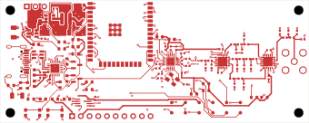
The routing image is a separate experimental candidate, not the main placement file or a fabrication package. Bottom and inner routes are not shown here.
Schematic SVG · Latest design report · Draft BOM · Roadmap
Latest work: A3 replaces the power supply and RF switches, completes routed connectivity, adds safe RF boot sequencing and proposes all populated parts. See engineering decisions and first-power instructions and the pre-order blocker report. The crystal was relocated and rerouted: all 180 artifact checks and six route screens now pass. Independent/supplier reviews remain pending. No hardware has been tested. Do not order historical A2 files.

Stock module reference image: Espressif, linked from the manufacturer's site. This is not a photo of the custom board or a guarantee of the N8 marking.
The actual component is an Espressif module, not an entire stock development board soldered onto another PCB. The selected N8 variant has 8 MB flash; its ESP32 provides a dual-core processor, 2.4 GHz Wi-Fi and Bluetooth. Its PCB antenna is separate from the sub-GHz SMA path. The antenna section extends beyond the custom base board to preserve its keepout. Module datasheet.
Power/programming uses ESP32 development-board conventions: USB-to-UART, automatic reset/boot control and manual BOOT/RESET buttons. This is not a pin-compatible clone of a particular commercial DevKit. Espressif ESP32-DevKitC reference.

Representative package image: Texas Instruments. This is the IC package, not a complete CC1101 antenna module; package markings may differ.
The PCB integrates CC1101RGPR directly, with its crystal, bypass capacitors, balun, switches and matching/filter components. TI specifies tuning ranges of 300–348, 387–464 and 779–928 MHz. That does not make every frequency or antenna equally usable or establish this board's RF performance. CC1101 product information and datasheet.
The separate Amazon CC1101 module supplied by the owner was a functional starting point. Its exact internal circuit and advertised four-band performance have not been independently verified here. The switched RF topology and initial component values also reference the M5Stack Cap CC1101 schematic. This is a different implementation, not an endorsed M5Stack product.
| Function | Current design choice |
|---|---|
| USB-C | HRO TYPE-C-31-M-12, USB 2.0 connection |
| USB-to-UART | Silicon Labs CP2102N-A02-GQFN24 |
| 3.3 V regulator | AP63203WU-7 buck, XAL4030 4.7 uH inductor |
| USB startup / UART isolation | TPS22918, SN74LVC2G125; J4 ships unjumpered |
| Radio reference | Abracon ABM8, 26 MHz; load requires validation |
| RF selection | Two pSemi PE42442A-Z SP4T switches; three paths used |
| RF balun | B0310J50100AHF |
| Antenna connector | Amphenol 132134, vertical standard SMA female, 50 ohm |
See third-party notices for provenance, image credits and license boundaries. Parts remain subject to sourcing, footprint and assembly approval; the BOM is not an approved shopping list.
| Feature | Planned behavior | Status |
|---|---|---|
| Four target bands | 315 / 433 / 868 / 915 MHz, one selected at a time | Not RF-validated |
| Software band switching | GPIO-operated RF switches; no DIP switches | Circuit present; firmware isolation only |
| Three RF branches | Dedicated 315 and 433 paths; shared 868/915 path | Matching, loss and isolation unmeasured |
| Single sub-GHz SMA | Vertical connector opposite USB-C | Placed; mechanical approval pending |
| USB-C power/programming | 5 V input, USB-to-UART flashing/logging | Captured; not bench-tested |
| Wi-Fi / Bluetooth | Available through the ESP32 module | Application integration planned |
| Developer controls | BOOT, RESET, LEDs and test pads | Included in draft |
| Expansion | Optional DNP 10-pin header | Included in draft |
| PCB | 90 × 36 mm base, four layers, nominal 1.6 mm | Stackup/impedance release pending |
| Safe bring-up | RF paths isolated; no transmit command | Implemented in initial firmware |
Band switching changes the hardware path. Future firmware must also set the radio frequency/modem registers and operating limits. One CC1101 cannot listen on all four bands simultaneously. Use an antenna suitable for the selected band; a shared SMA does not imply a universal antenna.
There is no native USB, USB-PD, battery charger, finished RF application or guaranteed protocol compatibility in this revision.
Snapshot: 2026-09-26, KiCad 10.0.6. Design-file checks, not lab results.
| Check | Result |
|---|---|
| Schematic ERC | 0 reported violations |
| Main placement seed DRC | 0 violations; 283 unconnected items (not the routed board) |
| Targeted artifact checks | 180 / 180 passing on refined candidate / explicit seed checks |
| Added route screens | 6 / 6 passing; oscillator routing, cross-layer clearance and modeled DC drops |
| Separate A3 routed candidate DRC | 0 violations; 0 unconnected items |
| Fresh schematic / routed PCB comparison | Every numbered pad net, value and footprint name matches |
| Layer constraints | No signal traces on In1; RF/clock top-only; documented USB crossover |
| Candidate power routing | Main rails explicitly routed; 60 narrower branch/neck segments listed; critical copper paths quantitatively screened |
| Parts selection | 94 / 94 populated positions have proposed exact parts; sourcing unapproved |
| Physical boards tested | None |
Zero reported violations does not prove working or compliant hardware. A3's power redesign addresses the earlier LDO heat problem and the new switches cover the target bands in their specified frequency range. Actual power sequencing, temperature, impedance, matching and crystal startup/frequency remain unmeasured. C21 and U5 contain in-pad vias requiring filled/capped processing; supplier DFM confirmation is mandatory. USB power must be configured before fitting J4, and full combined Wi-Fi/radio load is not approved.
Raw reports · Verification checklist · Power, routing and RF validation plan
The detailed roadmap uses acceptance criteria, not promised dates. There is no release date, sales price, preorder or claim of certification.
Open hardware/esp32-cc1101-multiband.kicad_pro in KiCad 10 for the main
placement seed and schematic. Open hardware/A3-routing-candidate.kicad_pro
separately for the unapproved routing experiment. Do not order either one.
Python generators are the editable source for this checkpoint. Regenerating placement overwrites the generated board; preserve manual routing first. See rebuild instructions and firmware instructions.
Initial firmware resets the CC1101, checks repeated PARTNUM/VERSION reads and stable IDLE state, and logs explicit failures. It does not configure a receiver or transmitter and has not run on physical hardware. Passing digital diagnostics is not proof of authenticity or RF qualification.
This project is developed with substantial assistance from OpenAI Codex under the owner's direction. AI assisted with component research, schematic/PCB generators, footprints, experimental routing, firmware, documentation and review. Design images are KiCad renders/exports, not AI-generated product photographs.
AI output and automated checks can contain errors. They are not independent engineering approval, bench validation or regulatory certification. No physical prototype has been completed. Qualified human electrical/RF review remains a release gate. See the full AI disclosure.
This initial publication uses the Public Review License: non-commercial study/private evaluation is permitted; manufacturing, product sales and other uses beyond its limited permissions require written permission. Commercial rights are reserved while the owner's plans are undecided. This is source-available, not open-source/open hardware. Third-party terms are separate; see notices. Obtain legal advice before relying on the custom license for a commercial launch.
Use only with equipment and signals you own or are authorized to test. Tunable frequencies are not automatically permitted transmit frequencies. Final use and sale require applicable RF, EMC, product-safety and other compliance work. This prototype is not for safety-critical applications. No manufacturer named here endorses the project.
| Qty | Value | Footprint | References |
|---|---|---|---|
| 15 | 100nF | C_0402_1005Metric | C4, C6, C7, C12, C14, C21, C22, C23, C24, C25, C26, C30, C60, C61, C71 |
| 8 | DNP | C_0402_1005Metric | C43, C46, C48, C50, C51, C52, C53, C54 |
| 5 | 0R | L_0402_1005Metric | L43, L46, L47, L49, L50 |
| 5 | 10k | R_0603_1608Metric | R10, R11, R20, R21, R70 |
| 5 | 10k pullup | R_0603_1608Metric | R31, R32, R33, R34, R35 |
| 4 | MountingHole_2.7mm_M2.5 | MountingHole_2.7mm_M2.5 | MH1, MH2, MH3, MH4 |
| 3 | 10nH 5% | L_0402_1005Metric | L42, L44, L51 |
| 3 | 22uF 25V | C_1206_3216Metric | C1, C2, C13 |
| 2 | 100pF C0G | C_0402_1005Metric | C40, C41 |
| 2 | 10uF | C_0603_1608Metric | C11, C20 |
| 2 | 15pF C0G | C_0402_1005Metric | C31, C32 |
| 2 | 330R 1% | R_0603_1608Metric | R12, R13 |
| 2 | 4.7uF | C_0603_1608Metric | C3, C9 |
| 2 | 49.9R 1% | R_0402_1005Metric | R60, R61 |
| 2 | 5.1k 1% | R_0603_1608Metric | R1, R2 |
| 2 | MMBT3904 | SOT-23 | Q1, Q2 |
| 2 | PE42442A-Z | pSemi_PE42442_QFN24 | U3, U4 |
| 1 | +3V3 | TestPoint_Pad_D1.0mm | TP3 |
| 1 | 0.6pF C0G | C_0402_1005Metric | C42 |
| 1 | 0R | R_0402_1005Metric | R41 |
| 1 | 1.2pF C0G | C_0402_1005Metric | C44 |
| 1 | 100k | R_0603_1608Metric | R71 |
| 1 | 10nF | C_0402_1005Metric | C70 |
| 1 | 10pF C0G | C_0402_1005Metric | C47 |
| 1 | 15nH 5% | L_0402_1005Metric | L48 |
| 1 | 1M | R_0603_1608Metric | R4 |
| 1 | 1k | R_0603_1608Metric | R3 |
| 1 | 1uF | C_0603_1608Metric | C10 |
| 1 | 2.2nH 5% | L_0402_1005Metric | L52 |
| 1 | 22.1k 1% | R_0603_1608Metric | R5 |
| 1 | 3.3nH 5% | L_0402_1005Metric | L40 |
| 1 | 3.6nH 5% | L_0402_1005Metric | L45 |
| 1 | 4.7nF 1kV | C_1206_3216Metric | C5 |
| 1 | 4.7uH XAL4030 | L_Coilcraft_XAL4030-XXX | L1 |
| 1 | 47.5k 1% | R_0603_1608Metric | R6 |
| 1 | 56k 1% | R_0402_1005Metric | R30 |
| 1 | 6.2pF C0G | C_0402_1005Metric | C49 |
| 1 | 6.8nH 5% | L_0402_1005Metric | L41 |
| 1 | 600R@100MHz | L_0603_1608Metric | FB1 |
| 1 | 750mA PTC | Fuse_1206_3216Metric | F1 |
| 1 | 8pF C0G | C_0402_1005Metric | C45 |
| 1 | ABM8-26.000MHZ-10-1-U-T | Abracon_ABM8_4Pin_3.2x2.5mm | Y1 |
| 1 | AP63203WU-7 | Diodes_TSOT26 | U6 |
| 1 | B0310J50100AHF | TTM_B0310J50100AHF | B1 |
| 1 | BOOT | SW_Push_1P1T_NO_CK_KMR2 | SW2 |
| 1 | CC1101RGPR | Texas_RGP0020H_VQFN-20-1EP_4x4mm_P0.5mm_EP2.4x2.4mm_ThermalVias | U2 |
| 1 | CC1101_CSN | TestPoint_Pad_D1.0mm | TP7 |
| 1 | CC1101_GDO0 | TestPoint_Pad_D1.0mm | TP8 |
| 1 | CC1101_GDO2 | TestPoint_Pad_D1.0mm | TP9 |
| 1 | CP2102N-A02-GQFN24 | QFN-24-1EP_4x4mm_P0.5mm_EP2.6x2.6mm | U5 |
| 1 | DNP | C_0603_1608Metric | C8 |
| 1 | ESP32-WROOM-32E-N8 | ESP32-WROOM-32E | U1 |
| 1 | EXPANSION (DNP) | PinHeader_1x10_P2.54mm_Vertical | J3 |
| 1 | GND | TestPoint_Pad_D1.0mm | TP1 |
| 1 | PESD5V0S1UL | D_SOD-882 | D2 |
| 1 | POWER ARM AUTO / EXT | PinHeader_1x03_P2.54mm_Vertical | J4 |
| 1 | POWER GREEN | LED_0603_1608Metric | D4 |
| 1 | RESET | SW_Push_1P1T_NO_CK_KMR2 | SW1 |
| 1 | RF ESD DNP | D_0402_1005Metric | D5 |
| 1 | RF_SW0 | TestPoint_Pad_D1.0mm | TP10 |
| 1 | RF_SW1 | TestPoint_Pad_D1.0mm | TP11 |
| 1 | SMA FEMALE VERTICAL 50 OHM | SMA_Amphenol_132134_Vertical | J2 |
| 1 | SN74LVC2G125DCTR | SSOP-8_2.95x2.8mm_P0.65mm | U8 |
| 1 | SPI_MISO | TestPoint_Pad_D1.0mm | TP5 |
| 1 | SPI_MOSI | TestPoint_Pad_D1.0mm | TP6 |
| 1 | SPI_SCLK | TestPoint_Pad_D1.0mm | TP4 |
| 1 | STATUS GREEN | LED_0603_1608Metric | D3 |
| 1 | TPS22918DBVR | SOT-23-6 | U7 |
| 1 | UART_TX_ESP | TestPoint_Pad_D1.0mm | TP12 |
| 1 | USB-C USB2.0 | USB_C_Receptacle_HRO_TYPE-C-31-M-12 | J1 |
| 1 | USBLC6-2SC6 | SOT-23-6 | D1 |
| 1 | VBUS_PROTECTED | TestPoint_Pad_D1.0mm | TP2 |
bdini13/esp32-cc1101-multiband
Work-in-progress ESP32-WROOM-32E + CC1101 multiband PCB: software-selected 315/433/868/915 MHz paths. AI-assisted engineering draft; not manufacturing-ready.


Jonathan-0101/skeletonKey
BEng Dissertation; Penetration-testing device to highlight security system vulnerabilities

badgeteam/konsool-zero
RFID NFC <1GHz radio Konsool expansion board

SmallCoral/c5-car
用 KiCad 10 打开 CoralC5-Expansion.kicadpro。这是 Coral-C5 的单槽扩展板,顶部 J14 接核心板,左右 J9、J8 各一组 2×24 排针,下方放 RJ45 和 microSD,右侧放 ESP32-C3-MINI-1U。100×86mm 板框为本项目暂定尺寸。

PotatoPeaSea/Rocky
Five-legged walking robot inspired by Rocky (Project Hail Mary).

florisvde/QN8007B-Breakout-Board
Breakout board for the Quintic QN8007B single-chip stereo FM transmitter with RDS.


It measures 90 × 36 mm and has 4 copper layers, 1.6 mm thick.
121 parts, built around the PE42442A-Z, CC1101RGPR, ESP32-WROOM-32E-N8 and SN74LVC2G125DCTR-JSM. The full list of its parts is on this page, with links to each part's symbol and footprint where PCBKit's library has them.
From the bdini13/esp32-cc1101-multiband repository on GitHub, at the commit this page was made from: the board is hardware/routing/A3-before-crystal-refinement.kicad_pcb and its schematic hardware/esp32-cc1101-multiband.kicad_sch. PCBKit opens the board in the browser, with nothing to install.
Its repository states no licence, so its author keeps all rights: ask bdini13 before reusing the design.