4 layers55.5 × 34.9 mm

 nspired-Hackers/nternet-Link58
Wi-Fi, AI chat, and camera module for TI-Nspire calculators. Custom ESP32 PCBs + firmware. (Yes, 'nternet' is intentional, Nspire community naming.)
Nlink lite is an open-source printed circuit board by nspired-Hackers, from the nspired-Hackers/nternet-Link repository on GitHub. It is a 4-layer board of 40 × 15 mm with 26 parts on 20 nets, routed with 213 tracks and 43 vias.
It is built around the ESP32-C3-MINI-1-N4, CP2102N-A02-GQFN24 and TLV62569DBV, with the USBLC6-2SC6 among its other parts. Its parts include 10 resistors, 7 capacitors, 4 ICs, 2 connectors and 1 diode. It belongs with the ESP32 and RISC-V boards of this library.


An open-hardware platform that turns a TI-Nspire graphing calculator into a networked handheld terminal. It adds Wi-Fi, an AI chat/tutor, a camera that reads and solves problems, and onboard storage, all through a small plug-in device.
New to the Nspire scene? The spelling "nternet" is intentional. The Nspire's name plays on "inspire", and community projects follow suit by dropping the first letter, like the Ndless jailbreak playing on "endless". nternet is "internet", Nspire style.
Over four generations the project grew from a soldered-in modification into a clean, reproducible, plug-in platform with a proper communication protocol and custom PCBs.
Not affiliated with or endorsed by Texas Instruments. This is an embedded-systems and networking experiment. It is not designed or intended for use during exams. Follow your institution's rules.
The V4 calculator UI runs as a live simulator. The on-screen calculator and a virtual ESP32 talk over the real V4 wire protocol, so you can experiment with the whole experience before building anything.
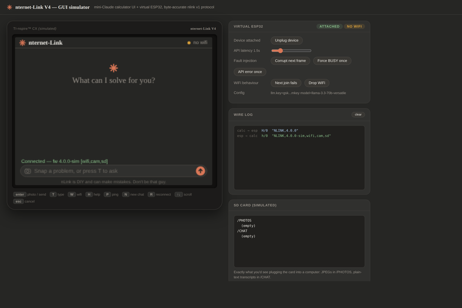
Open the live simulator,
or download v4/tools/gui_simulator.html and
open it in any browser (it runs fully offline).
Build V4. It is the current, recommended generation. The others are here as history and reference.
| Version | What it is | Build it? | |
|---|---|---|---|
| 🟢 | V4 | Rewritten firmware, protocol, and UI. Two custom PCBs: a full camera stick and a tiny chat-only board. Browser simulator, automated tests. | Yes, start here |
| ⚪ | V3 | First ESP32-S3 and camera platform, with a host proxy server. | Superseded |
| ⚪ | V2 | First external USB plug-in adapter (ESP32-C3). No calculator mod. | Superseded |
| ⚪ | V1 | The original: an ESP32 soldered inside the calculator. | Legacy / reference |
 TI-Nspire  =USB=>  nternet-Link device  =Wi-Fi=>  AI provider
 (keyboard,         (ESP32 + USB bridge             (Groq / OpenAI /
  screen, Lua)       + camera + SD)                  OpenRouter / local)
The calculator supplies the keyboard and screen and runs a Lua app. The device is an ESP32 that bridges USB-serial to Wi-Fi, calls an AI API, drives a camera, and stores photos and chat logs on a microSD card. In V4 the two sides speak nlink v1, a framed protocol with CRC checks and automatic retries.
README.md          you are here: the project hub
docs/              shared assets (hub images)
v1/                Ti-GPT, internal mod (legacy)
   firmware/       ESP32 .ino
   calculator/     Lua app + .tns
v2/                external adapter (docs)
v3/                ESP32-S3 and camera platform
   firmware/       ESP32 .ino
   calculator/     Lua app + .tns
   server/         host proxy server
v4/                CURRENT: the full rewrite
   README.md       tutorial and build guide (start here)
   src/ include/   ESP32 firmware (C++)
   calculator/     TI-Nspire Lua client + demo
   tools/          browser GUI simulator
   docs/           protocol spec
   test/           host-side tests
   hardware/       PCB design + 4 KiCad board variants
Each version folder has its own README. New here? Open v4/.
V1 (2025) proved the concept by soldering an ESP32 onto the calculator's USB lines. V2 moved all the electronics outside into a plug-in adapter, with no calculator modification. V3 jumped to the ESP32-S3 with a camera and a host proxy. V4 is the ground-up rewrite: a reliable checksummed protocol, no API keys in the source (they live in the device's flash), support for any OpenAI-compatible AI provider, a browser simulator, automated tests, and two custom circuit boards.
nternet-Link is a small side project, built in spare time and shared for free. If it's been useful to you and you'd like to chip in, tips go toward parts and the first run of ready made cables. No pressure at all, and thank you either way.

Open hardware and software. Modify, improve, and share. Built for learning about USB, serial protocols, embedded networking, and hardware interfacing.
| Qty | Value | Footprint | References |
|---|---|---|---|
| 4 | 10k | Resistor_SMD:R_0402_1005Metric | R6, R7, R9, R10 |
| 3 | 100n | Capacitor_SMD:C_0402_1005Metric | C1, C5, C6 |
| 2 | 10u | Capacitor_SMD:C_0805_2012Metric | C3, C7 |
| 1 | 100k | Resistor_SMD:R_0402_1005Metric | R5 |
| 1 | 1k | Resistor_SMD:R_0402_1005Metric | R1 |
| 1 | 2.2uH | Inductor_SMD:L_1210_3225Metric | L1 |
| 1 | 22.1k | Resistor_SMD:R_0402_1005Metric | R2 |
| 1 | 22u | Capacitor_SMD:C_0805_2012Metric | C4 |
| 1 | 4.7u | Capacitor_SMD:C_0402_1005Metric | C2 |
| 1 | 453k | Resistor_SMD:R_0402_1005Metric | R4 |
| 1 | 47.5k | Resistor_SMD:R_0402_1005Metric | R3 |
| 1 | 470 | Resistor_SMD:R_0402_1005Metric | R8 |
| 1 | CP2102N-A02-GQFN24 | Package_DFN_QFN:QFN-24-1EP_4x4mm_P0.5mm_EP2.6x2.6mm | U3 |
| 1 | ESP32-C3-MINI-1-N4 | Espressif:ESP32-C3-MINI-1 | U1 |
| 1 | LED_STATUS | LED_SMD:LED_0402_1005Metric | D1 |
| 1 | PROG_PADS_2x3_POGO | Connector_PinHeader_1.27mm:PinHeader_2x03_P1.27mm_Vertical_SMD | J4 |
| 1 | PWR_SW | Button_Switch_SMD:SW_SPDT_PCM12 | SW1 |
| 1 | TLV62569DBV | Package_TO_SOT_SMD:SOT-23-5 | U4 |
| 1 | USBLC6-2SC6 | Package_TO_SOT_SMD:SOT-23-6 | U5 |
| 1 | USB_MiniB_PLUG_to_calc | Connector_PinHeader_2.54mm:PinHeader_1x05_P2.54mm_Vertical | J1 |

PCB-Design-MIT/Wi-Fi-Controlled-RGB-Light
A demo board for students to learn to solder and debug

bdini13/esp32-cc1101-multiband
Work-in-progress ESP32-WROOM-32E + CC1101 multiband PCB: software-selected 315/433/868/915 MHz paths. AI-assisted engineering draft; not manufacturing-ready.


durveshpathak1989/kicad-local-agent
Free local Ollama agent for generating and validating KiCad project files

gjberger/pico2-starter
Bare-metal C on the Raspberry Pi Pico 2 (RISC-V), no SDK: linker script, minimal lib, UART loader

kaorii-ako/Poket
ESP32-S3 Bluetooth MP3 player - custom PCB + 3D-printed case, built from scratch

Matthew-Garcia/NASA-Lunabotics-UHCL-Lunar-Hawks
UHCL Lunar Hawks proof-of-concept excavation rover: ROS 2, micro-ROS, MicroPython, control PCB development, CAD, and research.
It measures 40 × 15 mm and has 4 copper layers, 1 mm thick.
26 parts, built around the ESP32-C3-MINI-1-N4, CP2102N-A02-GQFN24, TLV62569DBV and USBLC6-2SC6. The full list of its parts is on this page, with links to each part's symbol and footprint where PCBKit's library has them.
From the nspired-Hackers/nternet-Link repository on GitHub, at the commit this page was made from: the board is v4/hardware/kicad/nlink-lite/nlink-lite.kicad_pcb and its schematic v4/hardware/kicad/nlink-cam/nlink-cam.kicad_sch. PCBKit opens the board in the browser, with nothing to install.
Its repository states no licence, so its author keeps all rights: ask nspired-Hackers before reusing the design.