2 layers21 × 25 mm
DronecodeCANAdapter
generationmake/DronecodeCANAdapter
Small PCB with CAN transceiver and dronecode connectors JST GH
18 parts

 generationmake/CANFDZeroHAT27
Raspberry Pi HAT with Microchip MCP2518FD CAN FD controller
CANFDZeroHAT is an open-source printed circuit board by generationmake, from the generationmake/CANFDZeroHAT repository on GitHub. It is a 2-layer board of 65 × 30 mm with 32 parts on 26 nets, routed with 337 tracks and 32 vias.
It is built around the MCP2518FD-E/SL, 0ZCM0020FF2G and 150060GS75000, with the 150060RS75000, 150060YS75000 and JS202011JCQN among its other parts. Its parts include 12 resistors, 4 capacitors, 4 diodes, 4 connectors and 3 inductors.


Raspberry Pi HAT with Microchip MCP2517FD or MCP2518FD CAN FD controller
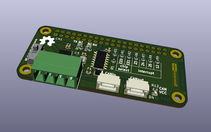
The board uses a 40 MHz crystal. This is the default crystal for the linux module. The first prototypes used a 20 MHz crystal.
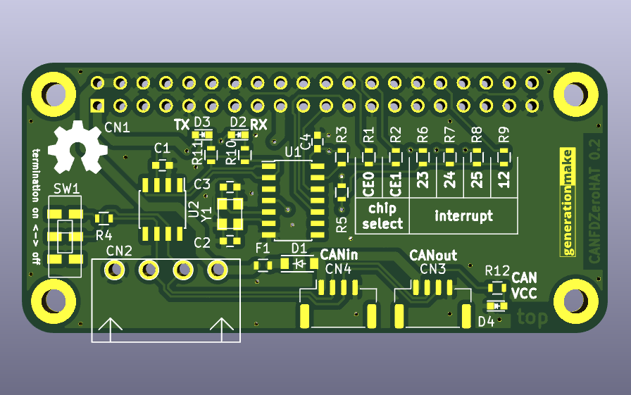
The controller can be connected to SPI0 CE0 or CE1 by populating different resistor jumpers. Also different GPIOs can be used as interrupt.
edit /boot/config.txt and add line:
dtoverlay=mcp251xfd,spi0-0,interrupt=25
If you use a crystal different to 40 MHz you have to specify the frequency:
dtoverlay=mcp251xfd,spi0-0,oscillator=20000000,interrupt=25
keep care that you choose the right interrupt and SPI CE line and populate the corresponding resistor.
enable CAN after boot up with
sudo ip link set can0 up type can bitrate 250000
Terminal block with 3.81 mm grid.
| Pin | Signal | Description |
|---|---|---|
| 1 | GND | |
| 2 | CAN_L | |
| 3 | CAN_H | |
| 4 | VCC | up to 5.5 V |
compatible to UAVCAN dronecode. JST GH 1.25mm 4-pin.
| Pin | Signal | Description |
|---|---|---|
| 1 | CANVCC | up to 5.5 V |
| 2 | CAN_H | |
| 3 | CAN_L | |
| 4 | GND |
CANVCC can be connected to the Raspberry Pi via diode D1 as desribed in the dronecode spec. The direction of the diode defines wether current is sourced from the connector or supplied into the UAVCAN system. If no connection is desired just leave D1 unpopulated.
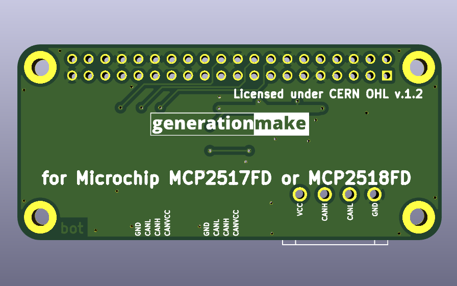
This hardware is licensed under the CERN OHL v. 1.2
| Qty | Value | Footprint | References |
|---|---|---|---|
| 4 | DNI | resistors:R_0603 | R2, R6, R7, R9 |
| 2 | 0R | resistors:R_0603 | R1, R8 |
| 2 | 100nF | capacitors:C_0603 | C1, C4 |
| 2 | 10k | resistors:R_0603 | R3, R5 |
| 2 | 1k | resistors:R_0603 | R10, R11 |
| 2 | 22pF | capacitors:C_0603 | C2, C3 |
| 2 | GH_SM04B-GHS-TB | Connector_JST:JST_GH_SM04B-GHS-TB_1x04-1MP_P1.25mm_Horizontal | CN3, CN4 |
| 1 | 0ZCM0020FF2G | resistors:R_0603 | F1 |
| 1 | 120R | resistors:R_0603 | R4 |
| 1 | 150060GS75000 | LEDs:LED_0603 | D2 |
| 1 | 150060RS75000 | LEDs:LED_0603 | D3 |
| 1 | 150060YS75000 | LEDs:LED_0603 | D4 |
| 1 | 2k | resistors:R_0603 | R12 |
| 1 | 691322310004 | CON_wuerth:WR-TBL_691322310004 | CN2 |
| 1 | DNI | diodes:SOD-123 | D1 |
| 1 | JS202011JCQN | mechanical-switches:CK_JS202011JCQN | SW1 |
| 1 | Label | labels:generationmake_logo | L2 |
| 1 | Label | labels:generationmake_small_solder | L1 |
| 1 | Label | Symbol:OSHW-Symbol_6.7x6mm_SilkScreen | L3 |
| 1 | MCP2518FD | SOIC:SOIC-14_3.9x8.7mm_Pitch1.27mm | U1 |
| 1 | RASPI-IO | MODULE_compute:RASPI_ZERO_HAT_EDGE | CN1 |
| 1 | RH100-40.000-18-F-2050-TR | crystals:Crystal_SMD_3.2x2.5mm_4Pad | Y1 |
| 1 | TCAN332GDR | SOIC:SOIC-8_3.9x4.9mm_Pitch1.27mm | U2 |
It measures 65 × 30 mm and has 2 copper layers, 1.6 mm thick.
32 parts, built around the MCP2518FD-E/SL, 0ZCM0020FF2G, 150060GS75000 and 150060RS75000. The full list of its parts is on this page, with links to each part's symbol and footprint where PCBKit's library has them.
From the generationmake/CANFDZeroHAT repository on GitHub, at the commit this page was made from: the board is kicad_source/CANFDZeroHAT.kicad_pcb. PCBKit opens the board in the browser, with nothing to install.
Its repository states no licence, so its author keeps all rights: ask generationmake before reusing the design.
generationmake/DronecodeCANAdapter
Small PCB with CAN transceiver and dronecode connectors JST GH

ut-ras/robomaster_hardware
Welcome! Please read the Wiki page for information on how to set up your computer and an overview of the projects in this repository.

ad4363/LuX-ray-PCBs
A repository containing KiCad schematic and pcb files for a wireless radiation detector testing interface

AndreasNielsen4000/Group-7-IoT-Project
The project is a wireless speaker system that can play music from a Bluetooth or WiFi source. The system consists of four main parts with subcomponents:

generationmake/ArduTrxShield
ArduTrx - Open Source Hamradio Transceiver for Arduino

KaitoTLex/RoboRyo
This is team1280's replacement for the Robo Rio for more redundant and less annoying controls.

DanielCusi/MoonJelly-robotics-PCB
Robotics PCB designed for Eurobot used by Wolvineers.
