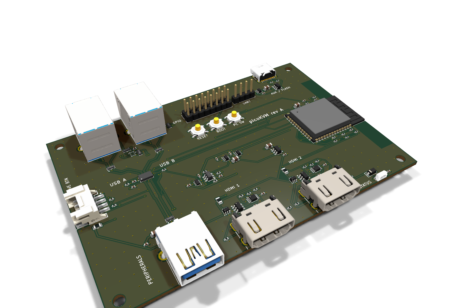
Kvm board is an open-source printed circuit board by FuNK3Y, from the FuNK3Y/picoKVM repository on GitHub. It is a 4-layer board of 112 × 75 mm with 95 parts on 75 nets, routed with 1,160 tracks and 500 vias.
It is built around the ESP32-S3-WROOM-1-N8R2, LM66100DCK and USBLC6-2SC6, with the PCA9306DC, AP2112K-3.3 and HD3SS3212IRKSR among its other parts. Its parts include 27 resistors, 25 capacitors, 22 ICs, 9 connectors and 3 switches. It belongs with the ESP32 boards of this library.
An inexpensive network KVM that can switch USB and monitor inputs simultaneously
Why
Samsung makes great monitors, but they often lack a KVM. The project started as a way to switch them along with the USB devices, over their network API. It was later generalized to most monitors, driven over HDMI DDC/CI by its own board, while still driving network-controlled monitors and devices.
Features
Switches the USB devices and the monitors' inputs together
Drives most monitors over HDMI DDC/CI, and others (or any device: a lamp, ...) over the network
No video goes through it: every computer is connected directly to every monitor, so HDCP, VRR, G-Sync, FreeSync, HDR, ... work natively
Controlled from its button, a web page or an HTTP API, from any device on the network
Hardware
picoKVM runs on its own board, designed in hardware/: an ESP32-S3, a USB 3.0 switch (two computers, one peripheral port), two HDMI ports carrying DDC/CI only (no video) to switch monitor inputs, an RGB status LED, and a Grove port for an M5Stack key unit as the switch button.
The original build (M5Stack AtomS3 Lite + USB multiplexer) is no longer supported; its last version is 5d5997c.
Install
Open the browser installer in Chrome or Edge, and plug the board's AUX / FLASH USB-C port into the computer.
Install, then connect the board to your Wi-Fi from the same page.
Computers' video goes directly to the monitors, as without a KVM.
Each computer's USB goes to the board; the keyboard and mouse go to its peripheral port, through a hub (the monitor's own hub works).
For monitors driven over DDC/CI, an HDMI cable goes from one of the board's HDMI ports to the monitor. It carries only the input-switch commands, no video. Monitors driven over the network need none.
The settings page (Settings, below the switch button at http://picokvm.local) edits everything: Wi-Fi, input names and colors, LED brightness, admin password, monitors and updates.
Admin password
Once set, the admin password protects everything the settings page does: opening it, reading and changing the configuration, and installing updates, from the page or through the API. The browser asks for it (any user name); API calls send it as HTTP Basic credentials, e.g. curl -u admin:<password>. Switching inputs, the state and /metrics stay open.
Until it is set, all of that is open to anyone on the network.
To remove it, use Clear password, then Save, on the settings page, or send "admin_password": null to /api/config; everything above is then open again.
It travels over plain HTTP, so anyone able to watch the network traffic can read it.
Monitors
Monitors are added on the settings page: a form for DDC/CI monitors, JSON for the others (config.example.json has an example of each).
DDC/CI monitors
Enable DDC/CI in the monitor's menu. For each computer, choose the monitor input it is on. The settings page reads the monitor: its name, the input it is on now, and the inputs it lists, named as the MCCS standard names them (VCP 0x60: 15 DisplayPort 1, 17 HDMI 1, ...). Some monitors use other values, or name their ports differently: put the monitor on each computer's input by hand, and the page shows which value it is (Other value... takes any number). Power the monitor on first wakes up monitors that keep DDC/CI alive in standby.
The monitor must accept DDC/CI on an input that is not the active one, since it is showing the other computer when the command arrives. Most do: tested on AOC, Samsung, Dell, Acer, Philips and Lenovo monitors. Some have no DDC/CI at all (the Samsung G80SD): drive those over the network.
Samsung monitors over the network
For Samsung smart monitors without DDC/CI, the KVM sends remote-control key presses: enable IP remote on the monitor (Connection > Network > Expert Settings). Find a repeatable sequence of keys that selects each input from the home screen, and write it with the key codes as a SamsungMonitor. KEY_RETURN first also wakes the monitor up; command_delay (or a delay on one key) slows the sequence down if the menu cannot keep up.
Other network devices
A GenericDevice sends an HTTP request for each input: another monitor's API (e.g. SmartThings, untested), a lamp, ...
Use
Switch with the button, the web page at http://picokvm.local (it follows the KVM whoever switches it), or the API:
sh
curl -X POST http://picokvm.local/api/active_input/A   # or B; without the input, toggles
curl http://picokvm.local/api/active_input             # the state: active input, switching, last error
curl http://picokvm.local/api/events                   # the state as server-sent events, on every change
/api/config reads (GET) and writes (POST) the configuration, without the passwords, only admin_password_set tells whether one is set (admin password required). /metrics gives Wi-Fi signal, memory, USB power and version for Prometheus.
picokvm is the default hostname; it can be changed in the settings.
Updates
Check for updates, then Install, on the settings page installs the latest release over the network; Upload installs a firmware-ota.bin of your own. Settings are kept. The first boot of an update is a trial: if the device is not back on Wi-Fi within 2 minutes, it returns to the previous firmware.
MicroPython does not check GitHub's certificate when downloading a release: the SHA-256 GitHub publishes only guards against a corrupted download.
ESPHome
The board can also run ESPHome instead of this firmware, for a native Home Assistant integration (DDC/CI monitors only). Include the esphome/picokvm.yaml package, then name the computers and set the number of monitors:
yaml
packages:
  picokvm: github://FuNK3Y/picoKVM/esphome/picokvm.yaml@main

substitutions:
  inputs:
    a: Work laptop
    b: Gaming PC
  monitors: 2
Each monitor's input values and the LED colors and brightness are then set from Home Assistant. esphome/example.yaml is a complete starting point; it builds, but has not been run on a board yet.
Development
firmware/build.sh builds MicroPython with src/ frozen in, into firmware/build/ (needs ESP-IDF v5.5.2):
sh
. $IDF_PATH/export.sh
firmware/build.sh
CI runs the same build on pull requests and main and keeps the images as an artifact. A v* tag publishes a release and the installer to GitHub Pages.
The tests run the application on CPython, with stand-ins for the board (tests/mocks.py); CI requires 95% coverage:
It measures 112 × 75 mm and has 4 copper layers, 1.6 mm thick.
What parts does the Kvm board use?
95 parts, built around the ESP32-S3-WROOM-1-N8R2, LM66100DCK, USBLC6-2SC6 and PCA9306DC. The full list of its parts is on this page, with links to each part's symbol and footprint where PCBKit's library has them.
Where can I download the Kvm board KiCad files?
From the FuNK3Y/picoKVM repository on GitHub, at the commit this page was made from: the board is hardware/revA/kvm_board.kicad_pcb. PCBKit opens the board in the browser, with nothing to install.
Can I use the Kvm board design in my own project?
Its repository states no licence, so its author keeps all rights: ask FuNK3Y before reusing the design.
An optional Raspberry Pi Compute Module 5 carrier for Iasis. It plugs into the main board's HubPD population and carries Ethernet, NVMe storage, an accessory USB-C port and a service USB-C port.
A fast autorouter for KiCad boards that, above all, reroutes incrementally: given the previous route, it keeps what an edit left standing and routes again only what the edit disturbed.