2 layers
 fstp/computer_clock_module
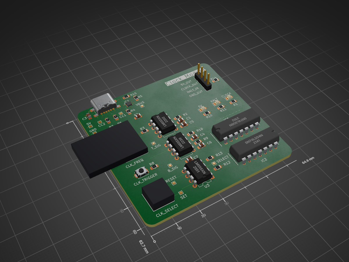
The clock module for my PCB computer
Timer 555 is an open-source printed circuit board by fstp, from the fstp/computer_clock_module repository on GitHub. It is a 4-layer board of 64.8 × 62.7 mm with 47 parts on 41 nets, routed with 222 tracks and 40 vias.
It is built around the SN74LS04N, SN74LS08N and TPS25200DRVR. Its parts include 16 resistors, 7 capacitors, 6 ICs, 3 diodes and 2 connectors. It belongs with the lEDs and displays boards of this library.


A dedicated PCB implementation of the clock module for a discrete 8-bit computer. This project is heavily inspired by Ben Eater's 8-bit computer series but adapts the breadboard schematics into a permanent, reliable Printed Circuit Board form factor. The clock module is the heartbeat of the computer. It synchronizes all operations across the bus, registers, and memory. This PCB module is designed to be modular, allowing it to be plugged into a larger backplane or connected via jumper wires to other components.
The circuit is built around the versatile 555 Timer IC. The design uses three distinct timers to handle signal generation and logic control:
The PCB exposes the following header pins:
| Name | Description |
|---|---|
| 5V_OUT | +5V supply output. |
| CLOCK_OUT | The clock output signal. |
| HALT_IN | The input halt signal. |
| GND_OUT | Ground supply output. |

Ben Eater: For the incredible 8-bit computer tutorial series which served as the primary inspiration for this project.| Qty | Value | Footprint | References |
|---|---|---|---|
| 4 | 10K | Resistor_SMD:R_0805_2012Metric_Pad1.20x1.40mm_HandSolder | R8, R12, R13, R14 |
| 3 | 10n | Capacitor_SMD:C_0805_2012Metric_Pad1.18x1.45mm_HandSolder | C5, C6, C7 |
| 3 | 220 | Resistor_SMD:R_0805_2012Metric_Pad1.20x1.40mm_HandSolder | R1, R10, R11 |
| 3 | LM555xN | Package_DIP:DIP-8_W7.62mm | U1, U2, U3 |
| 2 | 150k | Resistor_SMD:R_0805_2012Metric_Pad1.20x1.40mm_HandSolder | R5, R15 |
| 2 | 1K | Resistor_SMD:R_0805_2012Metric_Pad1.20x1.40mm_HandSolder | R2, R3 |
| 2 | 1M | Resistor_SMD:R_0805_2012Metric_Pad1.20x1.40mm_HandSolder | R9, R16 |
| 2 | 1u | Capacitor_SMD:C_0805_2012Metric_Pad1.18x1.45mm_HandSolder | C1, C4 |
| 2 | 5.1k | Resistor_SMD:R_0805_2012Metric_Pad1.20x1.40mm_HandSolder | R6, R7 |
| 1 | 0.1u | Capacitor_SMD:C_0805_2012Metric_Pad1.18x1.45mm_HandSolder | C3 |
| 1 | 22u | Capacitor_SMD:C_0805_2012Metric_Pad1.18x1.45mm_HandSolder | C2 |
| 1 | 33k | Resistor_SMD:R_0805_2012Metric_Pad1.20x1.40mm_HandSolder | R4 |
| 1 | 5V | TestPoint:TestPoint_Pad_1.0x1.0mm | TP1 |
| 1 | 5V | LED_SMD:LED_0805_2012Metric_Pad1.15x1.40mm_HandSolder | D2 |
| 1 | B_SIG | TestPoint:TestPoint_Pad_1.0x1.0mm | TP7 |
| 1 | CC1 | TestPoint:TestPoint_Pad_1.0x1.0mm | TP3 |
| 1 | CC2 | TestPoint:TestPoint_Pad_1.0x1.0mm | TP2 |
| 1 | CLK_FREQ | SamacSys_Parts:P160KN0QD15B1MEG | VR1 |
| 1 | CLK_SELECT | SamacSys_Parts:GPBS850N | S2 |
| 1 | CLK_TRIGGER | Button_Switch_SMD:SW_SPST_TS-1088-xR020 | SW1 |
| 1 | CLOCK | LED_SMD:LED_0805_2012Metric_Pad1.15x1.40mm_HandSolder | D1 |
| 1 | Conn_01x04 | Connector_PinHeader_2.54mm:PinHeader_1x04_P2.54mm_Vertical | J2 |
| 1 | GND | TestPoint:TestPoint_Pad_1.0x1.0mm | TP4 |
| 1 | HALT | LED_SMD:LED_0805_2012Metric_Pad1.15x1.40mm_HandSolder | D3 |
| 1 | RESET | TestPoint:TestPoint_Pad_1.0x1.0mm | TP10 |
| 1 | SELECT | TestPoint:TestPoint_Pad_1.0x1.0mm | TP8 |
| 1 | SET | TestPoint:TestPoint_Pad_1.0x1.0mm | TP9 |
| 1 | SN74LS04N | SamacSys_Parts:DIP794W53P254L1930H508Q14N | IC2 |
| 1 | SN74LS08N | SamacSys_Parts:DIP794W53P254L1930H508Q14N | IC3 |
| 1 | TPS25200DRVR | SamacSys_Parts:SON65P200X200X80-7N | IC1 |
| 1 | T_SIG | TestPoint:TestPoint_Pad_1.0x1.0mm | TP6 |
| 1 | USB_C_Receptacle_USB2.0_16P | Connector_USB:USB_C_Receptacle_GCT_USB4135-GF-A_6P_TopMnt_Horizontal | J1 |
| 1 | VBUS | TestPoint:TestPoint_Pad_1.0x1.0mm | TP5 |
It measures 64.8 × 62.7 mm and has 4 copper layers, 1.6 mm thick.
47 parts, built around the SN74LS04N, SN74LS08N and TPS25200DRVR. The full list of its parts is on this page, with links to each part's symbol and footprint where PCBKit's library has them.
From the fstp/computer_clock_module repository on GitHub, at the commit this page was made from: the board is timer_555.kicad_pcb and its schematic clock_module.kicad_sch. PCBKit opens the board in the browser, with nothing to install.
Its repository states no licence, so its author keeps all rights: ask fstp before reusing the design.

Grudz/6502_Computer
This repository stores everything for my 6502 project. This includes schematics, datasheets, C scripts, and assembly programs

baldengineer/bit-preserve
Project for capturing vintage, classic, aka old computer schematics in KiCad.

ForgottenMachines/Entrex
The technologies documented here will include all like-kind systems manufactured by Nixdorf, Redifon, ROCC & Mera, all originally designed by Entrex Inc, Burlington, MA USA.


imamunorzrashid/Break-System-Plausibility-Device
A standalone, analog Brake System Plausibility Device (BSPD) designed for Formula Student / Formula SAE Electric Vehicles.

Student-Satellite-IITB/Communication-Subsystem
Communication Subsystem for IITBSSP CubeSat Mission


taskx6004/limejig
Open-source LimeJig fixture firmware, host tools, KiCad source, and synthetic test examples