2 layers54.5 × 74.3 mm

 Grudz/6502_Computer1
This repository stores everything for my 6502 project. This includes schematics, datasheets, C scripts, and assembly programs
Clock module 6502 is an open-source printed circuit board by Grudz, from the Grudz/6502_Computer repository on GitHub. It is a 4-layer board of 133.4 × 151.8 mm with 69 parts on 117 nets, routed with 978 tracks and 83 vias.
It is built around the LM555CN, MC74HC00AD and SN74LS04N, with the SN74LS08N, SN74LS32N and EG1218 among its other parts. Its parts include 13 ICs, 11 resistors, 9 capacitors, 8 switches and 5 diodes. It belongs with the retro computing and games and lEDs and displays boards of this library.


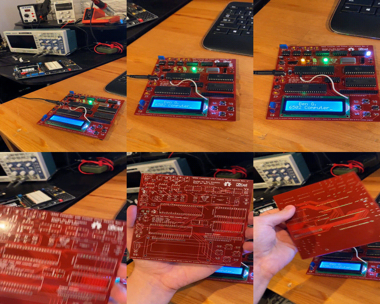
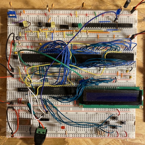
This repository stores everything for my 6502 project. This includes schematics, datasheets, C scripts, and assembly programs . Ben Eater designed a custom clock module and 6502 computer on a breadboard. I expanded on that project, by combining those and turning them into a PCB.
| Qty | Value | Footprint | References |
|---|---|---|---|
| 10 | 1k | Resistor_SMD:R_1206_3216Metric_Pad1.42x1.75mm_HandSolder | R1_U2, R1_U3, R1_U7, R1_UB1, R2_U1, R2_U3, R2_UB1, R3_U1, R3_UB1, R4_UB2 |
| 10 | TestPoint | TestPoint:TestPoint_Keystone_5000-5004_Miniature | A_Cap_U1, A_Cap_U1G1, A_Out_U1, A_Out_U1G1, M_Cap_U2, M_Cap_U2G1, M_Out_U2, M_Out_U2G1, Out_U5, Out_U5G1 |
| 6 | SW_Push_Dual | Button_Switch_THT:SW_Tactile_Straight_KSL0Axx1LFTR | SW1_U2, SW1_U7, SW1_UB1, SW2_UB1, SW3_UB1, SW4_UB1 |
| 5 | 220 | Resistor_SMD:R_1206_3216Metric_Pad1.42x1.75mm_HandSolder | R_Out1, R1_U1, R2_U2, R3_U3, R4_UB1 |
| 5 | LED | LED_THT:LED_D3.0mm_FlatTop | D1_U1, D1_U2, D1_U3, D1_U5, D1_UB1 |
| 4 | 0.1uF | Capacitor_THT:C_Disc_D7.5mm_W5.0mm_P5.00mm | C1_U2, C1_U7, C2_U1, C3_U2 |
| 3 | 0.01uF | Capacitor_THT:C_Disc_D7.5mm_W5.0mm_P5.00mm | C1, C1_U3, C2_U2 |
| 3 | LM555CN | Package_DIP:DIP-8_W7.62mm | U1, U2, U3 |
| 2 | 1uF | Capacitor_THT:CP_Radial_D5.0mm_P2.50mm | C1_U1, C2 |
| 2 | EG1218 | EG1218:EG1218 | SW1_U3, SWC_U14 |
| 1 | 10k | Potentiometer_THT:Potentiometer_Bourns_3296W_Vertical | RV1_U2 |
| 1 | 1M | Potentiometer_THT:Potentiometer_Bourns_3296W_Vertical | RV1_U1 |
| 1 | 1M | Resistor_SMD:R_1206_3216Metric_Pad1.42x1.75mm_HandSolder | R3_U2 |
| 1 | AT28C256 | Package_DIP:DIP-28_W15.24mm_Socket | U8_EEPROM1 |
| 1 | DGOF5S3 | Oscillator:Oscillator_DIP-14 | U13 |
| 1 | Debug_Monitor_Mount | Connector_PinHeader_2.54mm:PinHeader_2x17_P2.54mm_Vertical | J2 |
| 1 | HM62256LP-70 | Package_DIP:DIP-28_W15.24mm_Socket | U11_RAM1 |
| 1 | LED_Display | Display:WC1602A | U12 |
| 1 | MC74HC00A | SN74LS:SN74LS32N | U10 |
| 1 | Power_Jack | Connector_BarrelJack:BarrelJack_Horizontal | J3 |
| 1 | Power_Mount | Connector_PinHeader_2.54mm:PinHeader_1x02_P2.54mm_Vertical | J1 |
| 1 | SN74LS04N | SN74LS:SN74LS32N | U4 |
| 1 | SN74LS08N | SN74LS:SN74LS32N | U5 |
| 1 | SN74LS32N | SN74LS:SN74LS32N | U6 |
| 1 | Symbol_GNU-Logo_SilkscreenTop | Symbol:Symbol_GNU-Logo_SilkscreenTop | (this is only here b/c logo cool) |
| 1 | W65C02S | Package_DIP:DIP-40_W15.24mm_Socket | U7_CPU1 |
| 1 | W65C22S | Package_DIP:DIP-40_W15.24mm_Socket | U9_VIA1 |
The 67 most common of 69 parts.
It measures 133.4 × 151.8 mm and has 4 copper layers, 1.6 mm thick.
69 parts, built around the LM555CN, MC74HC00AD, SN74LS04N and SN74LS08N. The full list of its parts is on this page, with links to each part's symbol and footprint where PCBKit's library has them.
From the Grudz/6502_Computer repository on GitHub, at the commit this page was made from: the board is clock_module_6502/clock_module_6502.kicad_pcb. PCBKit opens the board in the browser, with nothing to install.
Its repository states no licence, so its author keeps all rights: ask Grudz before reusing the design.

baldengineer/bit-preserve
Project for capturing vintage, classic, aka old computer schematics in KiCad.


ForgottenMachines/Entrex
The technologies documented here will include all like-kind systems manufactured by Nixdorf, Redifon, ROCC & Mera, all originally designed by Entrex Inc, Burlington, MA USA.


chgopireddy/Full-Bridge-Class-D-Audio-Amplifier
LTspice Model for Full Bridge Class D, Voltage Mode Control, Peak Current Mode Control
