Skip to the content
4 layers75 × 50 mmCANchovy PCB, the printed circuit board in 3D

MKS CANable V2.0 based isolated USB-CAN interface

Size
75 × 50 mm
Copper layers
4
Thickness
1.6 mm
Parts
102
Nets
81
Pads
311
Tracks, vias
704, 275
Pours
377
Routed
Yes
KiCad
KiCad 8.0 (file 20240108)
Created
7 Oct 2023
Updated
6 Sep 2024

Overview

CANchovy PCB is an open-source printed circuit board by fred314159265, from the fred314159265/CANchovy repository on GitHub. It is a 4-layer board of 75 × 50 mm with 102 parts on 81 nets, routed with 704 tracks and 275 vias.

It is built around the STM32G431C8T6, B0505S-1WR3 and NC7SZ125P5X, with the TJA1051T/3/1, TPD4E1U06DCKR and ADUM1201BR among its other parts. Its parts include 20 capacitors, 20 resistors, 8 ICs, 3 diodes and 3 transistors. It belongs with the interfaces and adapters boards and the STM32 boards of this library.

Main components

11

README

README.md

CANchovy USB-CAN Interface

This repository contains the design file for an isolated USB-CAN interface PCB. It is based upon the MKS CANable V2.0 and is compatible with the CANable V2.0 firmware. It connects to the CAN bus via RJ45 connectors which can be configured with whatever pinout you require!
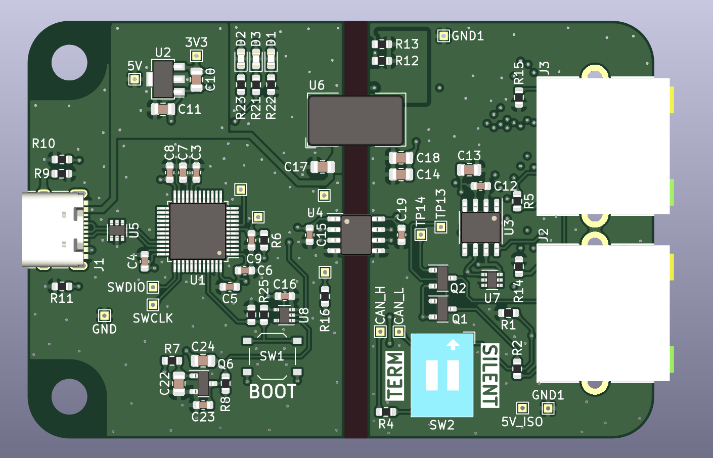
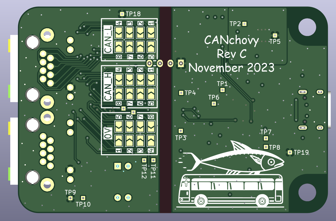
PCB-Top PCB-Top

Features

  • Firmware compatible with CANable V2.0 firmware - can be flashed & updated with the CANable 2.0 web updater.
  • RJ45 pinout configured via solder-able jumpers.
  • Galvanic isolation between CAN port and USB.
  • Two RJ45 connector in parallel allows for inserting inline on bus - all eight signal are passed through.
  • DIP switch to enable or disable CAN termination.
  • DIP switch to enable silent mode, preventing the CANchovy from transmitting on the bus in hardware.
  • JLCPCB basic parts used where possible and all parts available for JLCPCB assembly service. Five CANchovies fully assembled with postage costs around $20 per CANchovy.
  • 3D printed case design files.

Status

Assembled CANchovies from JLCPCB of both revision A & B have been tested and work correctly. The only issues with these version were silkscreen issues.

Revision C has the silkscreen fixed and is ready to manufacture and use.

Firmware

As the CANchovy is based upon the MKS CANable V2.0, it is compatible with firmware which is compatible with the MKS CANable V2.0.

There area couple of suitable firmware options - which firmware you will want to use really depends on your use case.

gs_usb

Using a firmware version which uses the gs_usb protocol will mostly be useful for SocketCAN on Linux, but python-can does support the gs_usb protocol on all platforms. (Note: The Linux kernel only supports CAN FD with the gs_usb driver after version 5.18.)

SLCAN

SLCAN is a protocol which operates over a serial port. Nearly all OS's have support for serial ports and so is very cross-platform. However, support for SLCAN is not very widespread.

You can also mount the serial port as a SocketCAN port on Linux (E.g. as described here.), however, it does not support FD CAN at this time.

FD CAN is possible with the SLCAN firmware, but even fewer programs support FD with SLCAN (if any?). It may be a viable for custom applications where non-Linux is a requirement and Python is not an option.

Configuring RJ45 Connections

As mentioned above, a feature of this board is that the RJ45's pinout is user configurable. By soldering one jumper for each of the three connections (0V, CAN_H, CAN_L) on the rear of the board, your custom CAN pinout over RJ45 can be supported!

Simply bridge one of the solder jumpers in each of the silkscreen boxes (labelled: 0V, CAN_H & CAN_L) to connect each signal to the corresponding pin number of the RJ45 connectors.

⚠⚠⚠ Care must be taken to ensure no two signals are connected to the same RJ45 pin! ⚠⚠⚠
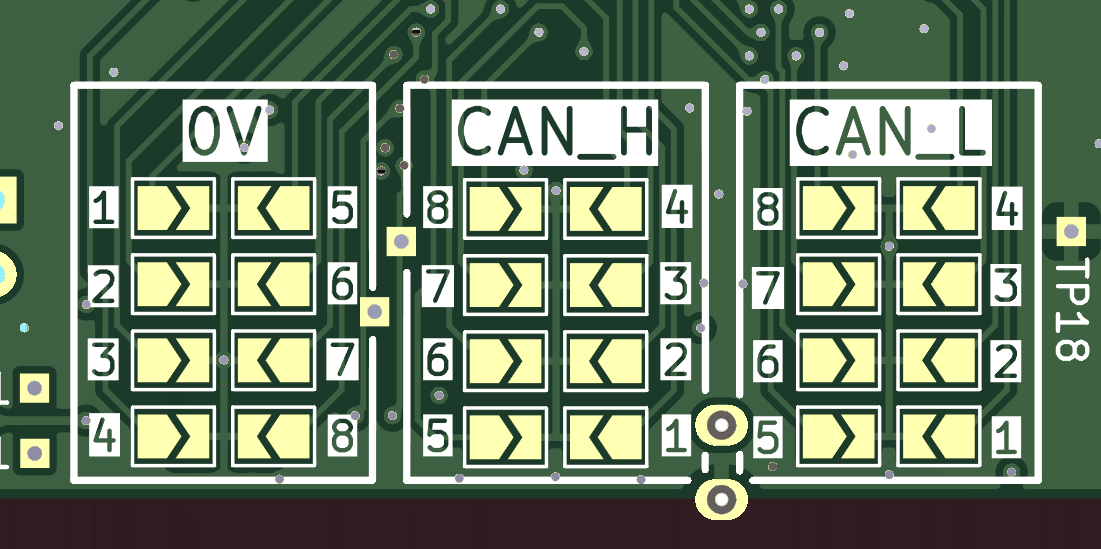
PCB-Top

Ordering

Gerbers, BOM, etc. can all be found in the releases area.

When ordering from JLCPCB, is is suggested to select "JLC04161H-7628" under the controlled impedance option, although the USB run is so short that even non-controlled impedance stack-ups will likely work too.

Parts

102
QtyValueFootprintReferences
16TestPointTestPoint:TestPoint_THTPad_1.0x1.0mm_Drill0.5mmTP1, TP2, TP3, TP4, TP5, TP6, TP7, TP8, TP9, TP10, TP11, TP12, TP13, TP14, TP18, TP19
12100nFCapacitor_SMD:C_0603_1608MetricC3, C4, C5, C6, C7, C8, C9, C12, C15, C16, C19, C23
61kResistor_SMD:R_0603_1608MetricR14, R15, R21, R22, R23, R25
54.7uFCapacitor_SMD:C_0805_2012MetricC14, C17, C18, C22, C24
310kResistor_SMD:R_0603_1608MetricR1, R6, R16
3120RResistor_SMD:R_0603_1608MetricR4, R12, R13
31uFCapacitor_SMD:C_0805_2012MetricC10, C11, C13
3OPT_1Jumper:SolderJumper-2_P1.3mm_Open_TrianglePad1.0x1.5mmJP1, JP9, JP17
3OPT_2Jumper:SolderJumper-2_P1.3mm_Open_TrianglePad1.0x1.5mmJP2, JP10, JP18
3OPT_3Jumper:SolderJumper-2_P1.3mm_Open_TrianglePad1.0x1.5mmJP3, JP11, JP19
3OPT_4Jumper:SolderJumper-2_P1.3mm_Open_TrianglePad1.0x1.5mmJP4, JP12, JP20
3OPT_5Jumper:SolderJumper-2_P1.3mm_Open_TrianglePad1.0x1.5mmJP5, JP13, JP21
3OPT_6Jumper:SolderJumper-2_P1.3mm_Open_TrianglePad1.0x1.5mmJP6, JP14, JP22
3OPT_7Jumper:SolderJumper-2_P1.3mm_Open_TrianglePad1.0x1.5mmJP7, JP15, JP23
3OPT_8Jumper:SolderJumper-2_P1.3mm_Open_TrianglePad1.0x1.5mmJP8, JP16, JP24
2100kResistor_SMD:R_0603_1608MetricR3, R8
25.1kResistor_SMD:R_0603_1608MetricR10, R11
2510RResistor_SMD:R_0603_1608MetricR2, R5
2AO3401APackage_TO_SOT_SMD:SOT-23Q1, Q2
2KH-RJ45-56-8P8C-DCANchovy_PCB:KH-RJ45-56-8P8C-DJ2, J3
2M4MountingHole:MountingHole_4.3mm_M4H1, H2
2TPD4E1U06DCKRPackage_TO_SOT_SMD:SOT-363_SC-70-6U5, U7
10RResistor_SMD:R_0603_1608MetricR9
11MResistor_SMD:R_0603_1608MetricR7
1ADuM1201BRPackage_SO:SOIC-8_3.9x4.9mm_P1.27mmU4
1B0505S-1WR3Converter_DCDC:Converter_DCDC_Murata_CRE1xxxxxx3C_THTU6
1BOOTButton_Switch_SMD:SW_Push_1P1T_XKB_TS-1187ASW1
1BlueLED_SMD:LED_0603_1608MetricD2
1DSWB02LHGETButton_Switch_THT:SW_DIP_SPSTx02_Slide_9.78x7.26mm_W7.62mm_P2.54mmSW2
1GreenLED_SMD:LED_0603_1608MetricD3
1HT7533-1Package_TO_SOT_SMD:SOT-89-3U2
1LOGOLOGOG***
1NC7SZ125P5XPackage_TO_SOT_SMD:SOT-353_SC-70-5U8
1RedLED_SMD:LED_0603_1608MetricD1
1SS8050Package_TO_SOT_SMD:SOT-23Q6
1STM32G431C8T6Package_QFP:LQFP-48_7x7mm_P0.5mmU1
1TJA1051T-3Package_SO:SOIC-8_3.9x4.9mm_P1.27mmU3
1USB_C_Receptacle_USB2.0Connector_USB:USB_C_Receptacle_XKB_U262-16XN-4BVC11J1

Similar boards

  • 4 layers408.7 × 50 mmPartial Drawer Controller v1, the printed circuit board in 3D

    Partial Drawer Controller v1

    Robast-GmbH/PCB_Designs

    This repository contains all the necessary files and instructions for the PCBs that are designed using KiCad. Here is an overview of the main components: - .github: Contains Github-specific configurations, including…

    619 parts1MIT
  • 2 layers100 × 64 mmRf power monitor rev2, the printed circuit board in 3D

    Rf power monitor rev2

    TheKingOfChaos/RF-Power-Monitor

    A 2-layer carrier board for the WIZnet W5500-EVB-Pico-PoE. It is 80 x 51.5 mm: exactly as long as the module, so both short edges line up with the module.

    129 parts
  • 6 layers24.9 × 51.5 mmDM0001, the printed circuit board in 3D

    DM0001

    dioderobot/demo

    Demo for diode boards

    147 parts3
  • 2 layers41 × 40.5 mmUSBIsolator, the printed circuit board in 3D

    USBIsolator

    NanashiTheNameless/USBIsolator

    A simple USB Isolator board with some simple functions that I find useful!

    8 parts1
  • 4 layers65 × 30 mmComposite vr, the printed circuit board in 3D

    Composite vr

    alanbog/Composite-VR-PCB

    Controller board for CRT-based VR headset

    208 partsCERN-OHL-P-2.0
  • 4 layers243.8 × 171.5 mmNeotron Pico, the printed circuit board in 3D

    Neotron Pico

    Neotron-Compute/Neotron-Pico

    A Neotron powered by the Raspberry Pi Pico

    242 parts250
  • 4 layers65 × 56.5 mmSH RPi, the printed circuit board in 3D

    SH RPi

    hatlabs/SH-RPi-hardware

    Sailor Hat for Raspberry Pi hardware design files

    168 parts56

Questions

How big is the CANchovy PCB PCB?

It measures 75 × 50 mm and has 4 copper layers, 1.6 mm thick.

What parts does the CANchovy PCB use?

102 parts, built around the STM32G431C8T6, B0505S-1WR3, NC7SZ125P5X and TJA1051T/3/1. The full list of its parts is on this page, with links to each part's symbol and footprint where PCBKit's library has them.

Where can I download the CANchovy PCB KiCad files?

From the fred314159265/CANchovy repository on GitHub, at the commit this page was made from: the board is CANchovy_PCB/CANchovy_PCB.kicad_pcb and its schematic CANchovy_PCB/8_way_select.kicad_sch. PCBKit opens the board in the browser, with nothing to install.

Can I use the CANchovy PCB design in my own project?

Its repository states no licence, so its author keeps all rights: ask fred314159265 before reusing the design.