2 layers80 × 51.5 mm
Pico poe mains carrier
TheKingOfChaos/RF-Power-Monitor
A 2-layer carrier board for the WIZnet W5500-EVB-Pico-PoE. It is 80 x 51.5 mm: exactly as long as the module, so both short edges line up with the module.
26 parts

 TheKingOfChaos/RF-Power-Monitor
A 2-layer carrier board for the WIZnet W5500-EVB-Pico-PoE. It is 80 x 51.5 mm: exactly as long as the module, so both short edges line up with the module.
Rf power monitor rev2 is an open-source printed circuit board by TheKingOfChaos, from the TheKingOfChaos/RF-Power-Monitor repository on GitHub. It is a 2-layer board of 100 × 64 mm with 129 parts on 86 nets, routed with 3,318 tracks and 305 vias.
It is built around the RP2040, TLV62569DBVR-TP and W25Q16JVSNIQ, with the LTV-814S-TA1, SN74LVC1G14DBVR and W5500 among its other parts. Its parts include 45 capacitors, 41 resistors, 8 ICs, 4 diodes and 4 connectors. It belongs with the radio and wireless boards and the RP2040 boards of this library.


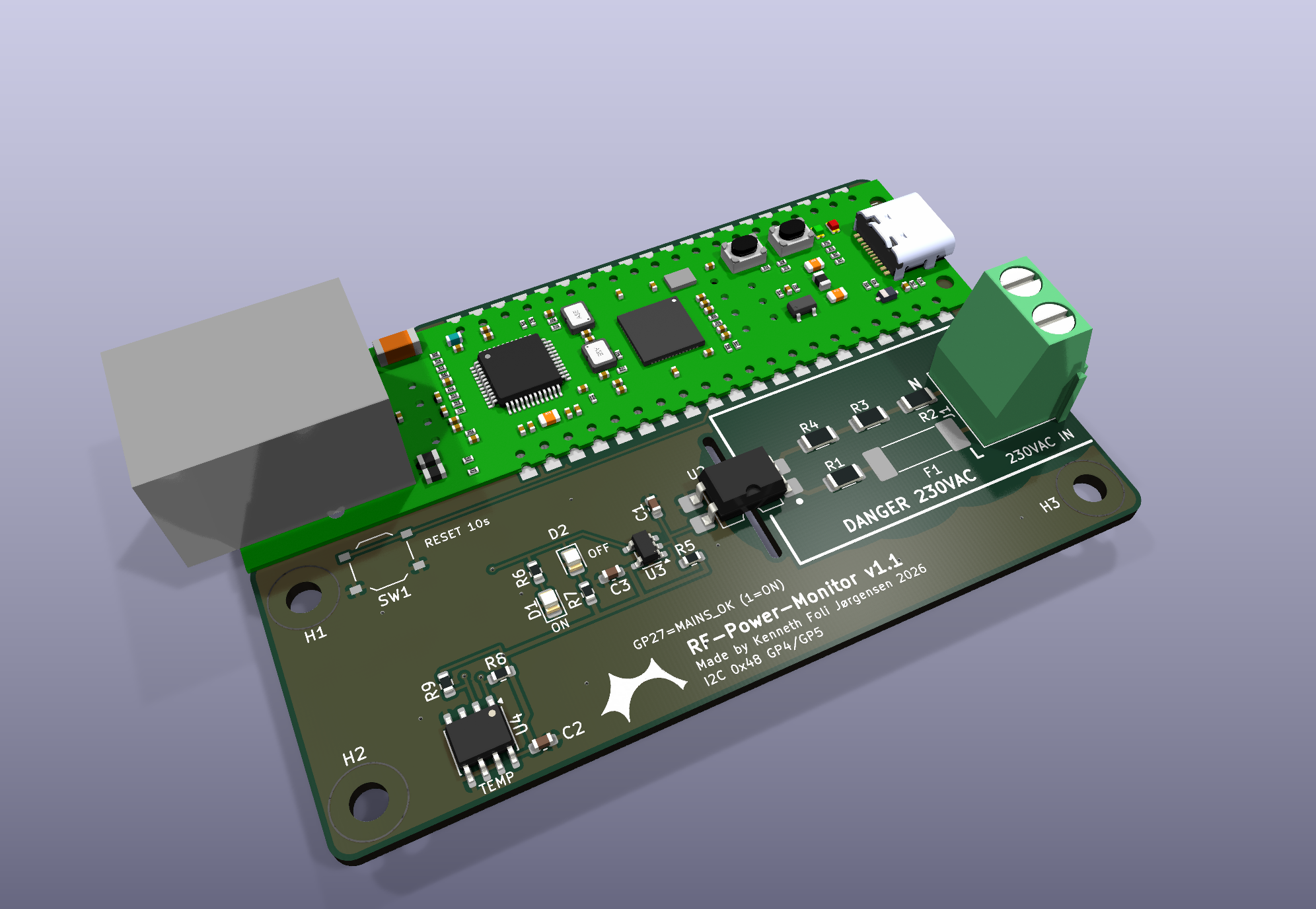
A 2-layer carrier board for the WIZnet W5500-EVB-Pico-PoE. It is 80 x 51.5 mm: exactly as long as the module, so both short edges line up with the module. The board extends 1.5 mm above the module for the solder fillets. It has 5x M3 holes, with centres at (4, 25.5), (4, 46) and (76, 46) mm from the module's top-left corner, plus H4 (30, 10.5) and H5 (66.5, 10.5) under the module, between the header rows. All SMD parts are on the top side. The only through-hole parts are the module headers and the screw terminal.
The successor, rev 2, puts the RP2040 and W5500 on one board with these circuits (designed, not built yet).
| Function | Connection |
|---|---|
| 230 VAC present / absent | GP27 (module pin 32): HIGH = mains present, LOW = mains absent |
| LED indication (hardware, no firmware needed) | Green D1 = mains ON, red D2 = mains OFF |
| Temperature | TMP1075 on I2C0: GP4 = SDA, GP5 = SCL, address 0x48 |
| Factory reset | SW1 from GP22 (module pin 29) to GND, below the module; hold 10 s (the firmware's internal pull-up holds GP22 high) |
| Power | From the module's 3V3(OUT) pin 36 (the module is PoE powered) |
GP16 to GP21 are used by the on-board W5500 and are not used here.
| Soldered flat | On female headers |
|---|---|
| 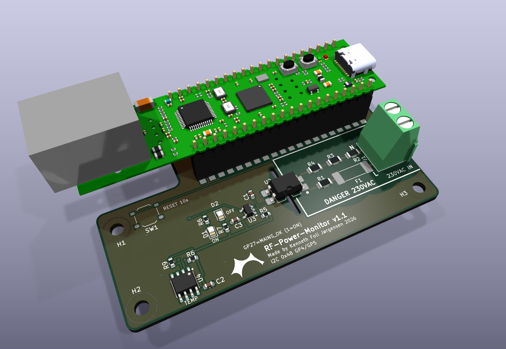 |
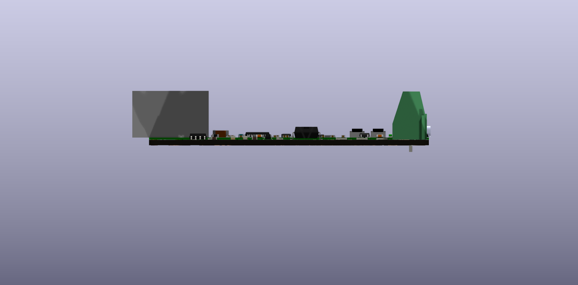 | 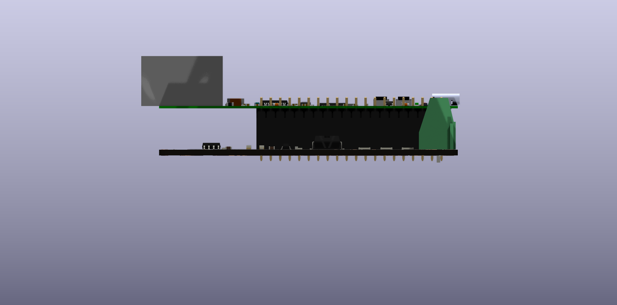 |
You can mount the module in either of two ways; the footprint supports both.
For flat mounting, the carrier has clearance for the parts that stick out under the module. The positions come from WIZnet's V1.1 drill file.
Trim any header pins under the module flush before soldering it down.
The mains area is on the right, below the module's USB end, outlined on silkscreen ("DANGER 230VAC"). The low-voltage logic, LEDs and temperature sensor are on the left. MAINS_OK, +3V3 and I2C reach them on the bottom layer, running between the module's two header rows.
pico-poe-mains-carrier.kicad_dru.pico-poe-mains-carrier.kicad_pro/.kicad_sch/.kicad_pcb: the KiCad 10 projectPicoPoE_Carrier.kicad_sym, PicoPoE_Carrier.pretty/: project symbols and the module footprintfab/: Gerbers and drill (zip), BOM and CPL in JLCPCB format, schematic PDF, STEP modeltools/generate.py: generates the whole project; tools/check.sh runs ERC and DRC; tools/fab.sh exports the fab filesThe firmware in this repository (C++, see the main README) runs on the module unchanged: it reads MAINS_OK on GP27 (HIGH = mains present) and uses the on-board W5500 on GP16-GP21. It reads the TMP1075 every 2 s as ambientTemperature (SNMP 63050.5, status screen, web page). Its 10 s factory reset reads SW1 on GP22 (active low).
from machine import Pin, I2C
mains = Pin(27, Pin.IN)
i2c = I2C(0, sda=Pin(4), scl=Pin(5), freq=400_000)
raw = i2c.readfrom_mem(0x48, 0x00, 2)
temp_c = ((raw[0] << 8 | raw[1]) >> 4) * 0.0625   # sign-extend for < 0 C
print("mains", "ON" if mains.value() else "OFF", "temp", temp_c)pico-poe-mains-carrier/
├── pico-poe-mains-carrier.kicad_pro KiCad 10 project
├── pico-poe-mains-carrier.kicad_sch schematic
├── pico-poe-mains-carrier.kicad_pcb PCB
├── pico-poe-mains-carrier.kicad_dru custom design rules (230 VAC isolation)
├── PicoPoE_Carrier.kicad_sym project symbol library
├── PicoPoE_Carrier.pretty/ project footprint library (module footprint)
├── sym-lib-table, fp-lib-table project library tables (paths are relative)
├── fab/ Gerbers, BOM, CPL, schematic PDF (see fab/README.md)
├── images/ renders: top, bottom, 3D and side views; module soldered flat
│ (iso, side-flat), on headers (*-headers) and carrier only
├── 3d/ STEP + GLB of the board with the module soldered flat and on
│ headers, STEP of the carrier only, and WIZnet's module model
└── tools/
├── generate.py generates the whole KiCad project
├── check.sh regenerate + ERC + DRC (needs kicad-cli 10)
├── fab.sh export the files in fab/
├── render.sh render images/ and export 3d/
└── stock_fp/ copies of the KiCad 10 library footprints usedAll library paths are relative (${KIPRJMOD}), so the folder works anywhere. For example, you can place it at hardware/pico-poe-mains-carrier/ in your firmware repository. Stock footprints and 3D models come from the standard KiCad 10 libraries.
tools/generate.py rewrites the schematic and PCB. If you edit the board by hand in KiCad, either copy the change into generate.py or stop using the generator; otherwise your edit will be overwritten.
3d/W5500-EVB-Pico-PoE_V1.1.step is WIZnet's 3D model of the module, from https://docs.wiznet.io/Product/Chip/Ethernet/W5500/W5500-EVB-Pico-PoE. The module footprint shows it soldered flat. The cutouts in the carrier match WIZnet's V1.1 drill file.
The footprints in tools/stock_fp/ are from the KiCad library, licensed CC-BY-SA 4.0 with an exception for designs made with them (https://www.kicad.org/libraries/license/).
| Qty | Value | Footprint | References |
|---|---|---|---|
| 22 | 100nF | PCM_rf-power-monitor-rev2:C_0402_1005Metric | C12, C13, C14, C15, C16, C17, C18, C25, C26, C27, C28, C29, C30, C31, C32, C33 +6 |
| 14 | TP_0.5mm | RFPM_Rev2:TestPoint_Pad_D0.5mm | TP1, TP2, TP3, TP4, TP5, TP6, TP7, TP8, TP9, TP10, TP11, TP12, TP13, TP14 |
| 5 | 4.7k | PCM_rf-power-monitor-rev2:R_0402_1005Metric_0402WGF1003TCE | R14, R15, R16, R40, R41 |
| 4 | 10nF 100V | PCM_rf-power-monitor-rev2:C_0603_1608Metric | C5, C6, C7, C8 |
| 4 | 3.3R | PCM_rf-power-monitor-rev2:R_0402_1005Metric | R17, R18, R21, R22 |
| 4 | 49.9R | PCM_rf-power-monitor-rev2:R_0402_1005Metric | R19, R20, R23, R24 |
| 4 | 68k 1206 200V | PCM_rf-power-monitor-rev2:R_1206_3216Metric | R33, R34, R35, R36 |
| 4 | 75R | PCM_rf-power-monitor-rev2:R_0402_1005Metric | R7, R8, R9, R10 |
| 4 | M3 | MountingHole:MountingHole_3.2mm_M3 | H1, H2, H3, H4 |
| 3 | 1k | PCM_rf-power-monitor-rev2:R_0402_1005Metric_0402WGF1003TCE | R29, R30, R31 |
| 3 | 22uF | PCM_rf-power-monitor-rev2:CL21A226MAQNNNE | C1, C2, C4 |
| 2 | 10uF | PCM_rf-power-monitor-rev2:C_0805_2012Metric | C3, C39 |
| 2 | 15pF | PCM_rf-power-monitor-rev2:C_0402_1005Metric_0402CG150J500NT | C40, C41 |
| 2 | 18pF | PCM_rf-power-monitor-rev2:C_0402_1005Metric_0402CG180J500NT | C21, C22 |
| 2 | 1nF 2kV | PCM_rf-power-monitor-rev2:C_1808_4520Metric | C9, C10 |
| 2 | 1uF | PCM_rf-power-monitor-rev2:C_0402_1005Metric_CL05A105KA5NQNC | C35, C36 |
| 2 | 27R | PCM_rf-power-monitor-rev2:R_0402_1005Metric | R27, R28 |
| 2 | 330R | PCM_rf-power-monitor-rev2:0402WGF3300TCE | R25, R26 |
| 2 | 4.7uF | PCM_rf-power-monitor-rev2:CL10A475KO8NNNC | C11, C19 |
| 2 | 5.1k | PCM_rf-power-monitor-rev2:R_0402_1005Metric | R1, R2 |
| 2 | 6.8nF | PCM_rf-power-monitor-rev2:C_0402_1005Metric | C23, C24 |
| 1 | 0R | PCM_rf-power-monitor-rev2:R_0402_1005Metric_0402WGF1003TCE | R13 |
| 1 | 100R | PCM_rf-power-monitor-rev2:R_0603_1608Metric | R38 |
| 1 | 100k | PCM_rf-power-monitor-rev2:R_0402_1005Metric_0402WGF1003TCE | R5 |
| 1 | 10k | PCM_rf-power-monitor-rev2:R_0402_1005Metric_RC0402FR-0710KL | R4 |
| 1 | 10nF | PCM_rf-power-monitor-rev2:CL05B103KB5NNNC | C20 |
| 1 | 12.4k 1% | PCM_rf-power-monitor-rev2:R_0402_1005Metric | R11 |
| 1 | 120R@100MHz | PCM_rf-power-monitor-rev2:L_0603_1608Metric | FB1 |
| 1 | 12MHz | PCM_rf-power-monitor-rev2:Crystal_SMD_Abracon_ABM8AIG-4Pin_3.2x2.5mm | Y2 |
| 1 | 1M | PCM_rf-power-monitor-rev2:R_0402_1005Metric | R12 |
| 1 | 1uF | PCM_rf-power-monitor-rev2:C_0603_1608Metric | C43 |
| 1 | 2.2uH | PCM_rf-power-monitor-rev2:IND-SMD_L3.0-W3.0 | L1 |
| 1 | 22k | PCM_rf-power-monitor-rev2:R_0402_1005Metric | R6 |
| 1 | 230VAC L/N | PCM_rf-power-monitor-rev2:TerminalBlock_Phoenix_MKDS-1,5-2-5.08_1x02_P5.08mm_Horizontal | J4 |
| 1 | 25MHz | PCM_rf-power-monitor-rev2:Crystal_SMD_3225-4Pin_3.2x2.5mm | Y1 |
| 1 | 330R | PCM_rf-power-monitor-rev2:R_0603_1608Metric | R39 |
| 1 | 470R | PCM_rf-power-monitor-rev2:R_0402_1005Metric | R32 |
| 1 | 47k | PCM_rf-power-monitor-rev2:R_0603_1608Metric | R37 |
| 1 | 5.6k | PCM_rf-power-monitor-rev2:R_0402_1005Metric | R3 |
| 1 | B5819W | PCM_rf-power-monitor-rev2:D_SOD-123 | D1 |
| 1 | BOOTSEL | PCM_rf-power-monitor-rev2:SW_Push_1P1T_XKB_TS-1187A | SW1 |
| 1 | Blue | PCM_rf-power-monitor-rev2:LED_0603_1608Metric | D2 |
| 1 | FACTORY RESET | PCM_rf-power-monitor-rev2:SW_Push_1P1T_XKB_TS-1187A | SW3 |
| 1 | Green | PCM_rf-power-monitor-rev2:LED_0805_2012Metric | D3 |
| 1 | HR601680 | PCM_rf-power-monitor-rev2:SMD-16_L12.7-W7.2-P1.27-LS9.5-BL | T1 |
| 1 | LTV-814S | PCM_rf-power-monitor-rev2:SMDIP-4_W9.53mm | U6 |
| 1 | RESET | PCM_rf-power-monitor-rev2:SW_Push_1P1T_XKB_TS-1187A | SW2 |
| 1 | RJ45 | PCM_rf-power-monitor-rev2:RJ45-TH_KH-RJ45-56-8P8C-D | J2 |
| 1 | RP2040 | PCM_rf-power-monitor-rev2:QFN-56-1EP_7x7mm_P0.4mm_EP3.2x3.2mm | U4 |
| 1 | Red | PCM_rf-power-monitor-rev2:LED_0805_2012Metric | D4 |
| 1 | SN74LVC1G14DBVR | PCM_rf-power-monitor-rev2:SOT-23-5 | U7 |
| 1 | SWD | Connector_PinHeader_2.54mm:PinHeader_1x03_P2.54mm_Vertical | J3 |
| 1 | T1A 250VAC | PCM_rf-power-monitor-rev2:Fuse_Schurter_UMT250 | F1 |
| 1 | TLV62569DBVR | PCM_rf-power-monitor-rev2:SOT-23-5 | U1 |
| 1 | TMP1075DR | PCM_rf-power-monitor-rev2:SOIC-8_3.9x4.9mm_P1.27mm | U8 |
| 1 | USB-C | PCM_rf-power-monitor-rev2:USB_C_Receptacle_HRO_TYPE-C-31-M-12 | J1 |
| 1 | W25Q16JVSNIQ | PCM_rf-power-monitor-rev2:SOIC-8_3.9x4.9mm_P1.27mm | U5 |
| 1 | W5500 | PCM_rf-power-monitor-rev2:LQFP-48_7x7mm_P0.5mm | U3 |
| 1 | WIZPoE-P1 | RFPM_Rev2:WIZPoE-P1 | U2 |
TheKingOfChaos/RF-Power-Monitor
A 2-layer carrier board for the WIZnet W5500-EVB-Pico-PoE. It is 80 x 51.5 mm: exactly as long as the module, so both short edges line up with the module.

CappyT/freedo
Local coordinator for tado V3+ heating devices, with a Home Assistant integration and add-on


ara-mkr/f405-flight-controller
This is a flight controller I designed as a side project. It was fun and pretty challenging, and I'm planning to build a drone with it at some point!

TKAman23/AERoS
An All-Encompassing Rocket System (AERoS) currently in development

fquinto/abb-welcome-gateway
ESP32 gateway for ABB‑Welcome / Busch‑Welcome 2‑wire intercoms. Doorbell notifications + remote door control in Home Assistant. Includes PCB design and firmware.


It measures 100 × 64 mm and has 2 copper layers, 1.6 mm thick.
129 parts, built around the RP2040, TLV62569DBVR-TP, W25Q16JVSNIQ and LTV-814S-TA1. The full list of its parts is on this page, with links to each part's symbol and footprint where PCBKit's library has them.
From the TheKingOfChaos/RF-Power-Monitor repository on GitHub, at the commit this page was made from: the board is hardware/rf-power-monitor-rev2/kicad/rf-power-monitor-rev2.kicad_pcb and its schematic hardware/pico-poe-mains-carrier/pico-poe-mains-carrier.kicad_sch. PCBKit opens the board in the browser, with nothing to install.
Its repository states no licence, so its author keeps all rights: ask TheKingOfChaos before reusing the design.