2 layers51.9 × 52 mm

 foxel/esp-dual-rf-switch6
LightFox Dual: esp8266 WiFi+RF dual channel switch
Esp switch is an open-source printed circuit board by foxel, from the foxel/esp-dual-rf-switch repository on GitHub. It is a 2-layer board of 50.8 × 50.8 mm with 29 parts on 27 nets, routed with 306 tracks and 12 vias.
It is built around the ATTINY441-SSU, HLK-PM03 and BT137, with the MOC3041M among its other parts. Its parts include 9 resistors, 5 ICs, 4 diodes, 4 connectors and 1 capacitor. It belongs with the radio and wireless boards and the ESP8266 and AVR (ATmega, ATtiny) boards of this library.


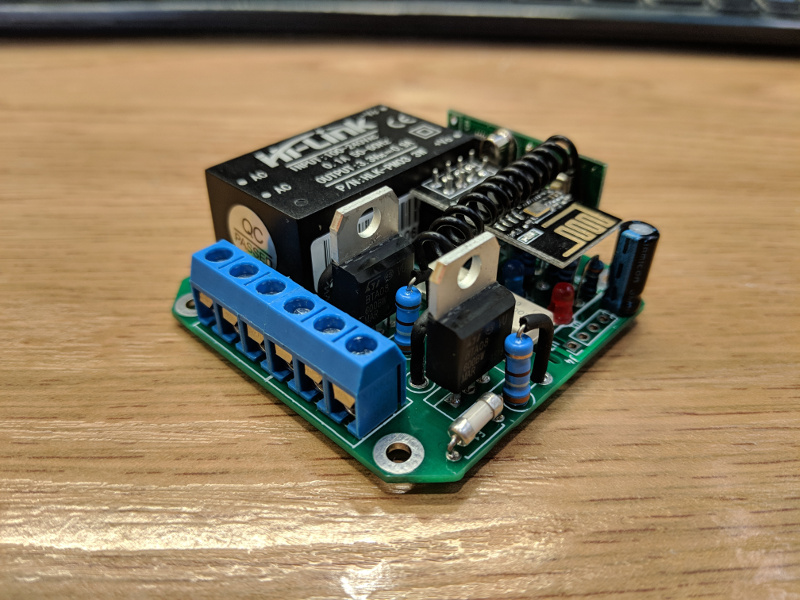
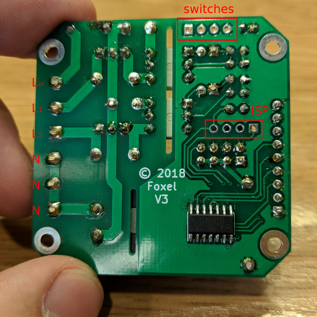
The board has following connectors:
Lin, L1, L2, N). Mains supply should be connected to Lin and one of N terminals. The loads are connected to L1/L2 and one of N terminals.RST, MOSI, MISO, SCL)L1, L2, 3V3, GND.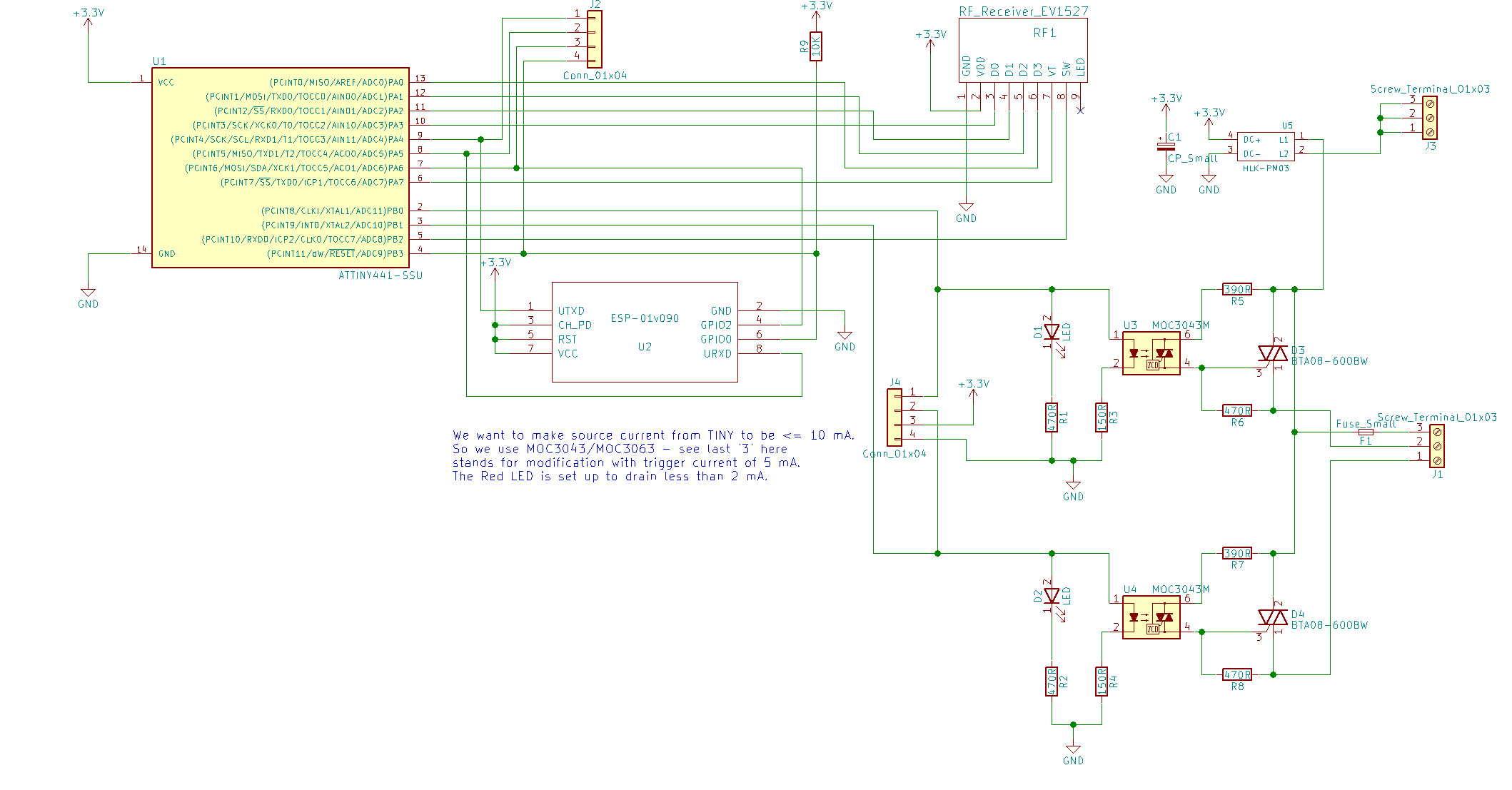
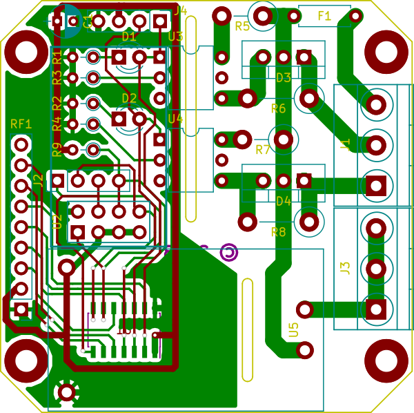
There are two microcontrollers to run this switch
ESP-01 - use one of available firmware options:
ATTINY441 - firmware is in attiny-firmware folder. This requires ATTinyCore to build
To flash ESP module connect it to PC any available way (e.g. USB-Serail adapter + breadboard) and follow selected firmware option flashing instructions.
To flash ATTINY:
| Item | Qty | Reference(s) | Link |
|---|---|---|---|
| 100uF, 5v | 1 | C1 | |
| 3mm red LED | 2 | D1, D2 | |
| BTA08-600BW | 2 | D3, D4 | |
| 1A fuse | 1 | F1 | |
| Screw Terminal 01x03 | 2 | J1, J3 | |
| 4pin header | 2 | J2, J4 | |
| 470R, 0.125W | 2 | R1, R2 | |
| 150R, 0.125W | 2 | R3, R4 | |
| 390R, 0.5W | 2 | R5, R7 | |
| 470R, 0.5W | 2 | R6, R8 | |
| 10K, 0.125W | 1 | R9 | |
| Itead.cc RF receiver | 1 | RF1 | https://www.itead.cc/rf-receiver-module-433mhz.html |
| ATTINY441-SSU | 1 | U1 | |
| ESP-01S | 1 | U2 | |
| MOC3043M/MOC3063M | 2 | U3, U4 | |
| HLK-PM03 | 1 | U5 |
| Qty | Value | Footprint | References |
|---|---|---|---|
| 4 | 470R | Resistors_THT:R_Axial_DIN0204_L3.6mm_D1.6mm_P2.54mm_Vertical | R1, R2, R3, R4 |
| 2 | 390R | Resistors_THT:R_Axial_DIN0411_L9.9mm_D3.6mm_P5.08mm_Vertical | R5, R7 |
| 2 | 470R | Resistors_THT:R_Axial_DIN0411_L9.9mm_D3.6mm_P7.62mm_Vertical | R6, R8 |
| 2 | BT137 | TO_SOT_Packages_THT:TO-220_Vertical | D3, D4 |
| 2 | Conn_01x04 | Pin_Headers:Pin_Header_Straight_1x04_Pitch2.54mm | J2, J4 |
| 2 | LED | LEDs:LED_D3.0mm | D1, D2 |
| 2 | MOC3041M | Housings_DIP:DIP-6_W7.62mm | U3, U4 |
| 2 | Screw_Terminal_01x03 | Connectors_Terminal_Blocks:TerminalBlock_Pheonix_MKDS1.5-3pol | J1, J3 |
| 1 | 10K | Resistors_THT:R_Axial_DIN0204_L3.6mm_D1.6mm_P2.54mm_Vertical | R9 |
| 1 | ATTINY441-SSU | Housings_SOIC:SOIC-14_3.9x8.7mm_Pitch1.27mm | U1 |
| 1 | CP_Small | Capacitors_THT:CP_Radial_D4.0mm_P2.00mm | C1 |
| 1 | ESP-01v090 | ESP8266:ESP-01 | U2 |
| 1 | Fuse_Small | Resistors_THT:R_Axial_DIN0207_L6.3mm_D2.5mm_P7.62mm_Horizontal | F1 |
| 1 | HLK-PM03 | Power_Supply:HLK-PM05 | U5 |
| 1 | RF_Receiver_EV1527 | footprints:RF_Receiver_Decoder | RF1 |
The 25 most common of 29 parts.


baranovskiykonstantin/aquarium
Control the lighting and the heating of the aquarium.

kr4fty/DiySolderingStation
Diy Soldering Stations with Atmega (Arduino UNO). Firmware and hardware design included


hecko/nanoReflowController
(c) 2017 David Sanz Kirbis (c) 2014 Karl Pitrich in part based on a project (c) 2013 Ed Simmons

MateoCignetti/ProyectoFinal
Esta obra está bajo una [Licencia Creative Commons Atribución-NoComercial-CompartirIgual 4.0 Internacional][cc-by-nc-sa].
It measures 50.8 × 50.8 mm and has 2 copper layers, 1.6 mm thick.
29 parts, built around the ATTINY441-SSU, HLK-PM03, BT137 and MOC3041M. The full list of its parts is on this page, with links to each part's symbol and footprint where PCBKit's library has them.
From the foxel/esp-dual-rf-switch repository on GitHub, at the commit this page was made from: the board is esp-switch.kicad_pcb. PCBKit opens the board in the browser, with nothing to install.
Its repository states no licence, so its author keeps all rights: ask foxel before reusing the design.