
2 layers73.7 × 61 mm

 exotwist/wake-up-light
Waking up to an electronic Sun.
Wul v21 is an open-source printed circuit board by exotwist, from the exotwist/wake-up-light repository on GitHub, published under the BSD-3-Clause licence. It is a 2-layer board of 100 × 70 mm with 73 parts on 22 nets, routed with 161 tracks and 4 vias.
It is built around the BT137. Its parts include 11 resistors, 6 diodes, 5 capacitors, 4 connectors and 2 fuses. It belongs with the AVR (ATmega, ATtiny) boards of this library.
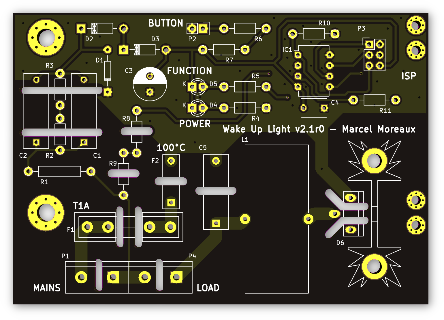
This is a dawn simulation lamp I made for my personal use.
A dawn simulator wakes you up by simulating sunrise in the bedroom; the increasing amount of light starts preparing your body for awakening. The end result is that you naturally wake up on your own, instead of being jarred awake by the usual alarm clock sounds.
When it receives power, the wake-up light
The wake-up light is switched on by a plug-in timer that activates 45 minutes before my intended rise time.
It also includes a button to toggle the light between off and full brightness, so I can turn it off after I get up.
The light controller is a classic phase-cutting triac dimmer, with zero-cross detection and triac control performed by a small microcontroller. The dimmer drives a 150W halogen floodlight, which gives a nice orange glow at low brightness, but provides reasonably white full-spectrum light at high brightness.
The design was also a bit of an engineering exercise; I wanted to end up with a fairly minimal design without compromising stability or reliability.
The controller is not isolated from mains; it uses a capacitive dropper power supply, and the MCU is connected directly to the triac. As a result, the entire circuit may be at mains potential, it must be installed so that users can't touch any of it. This also applies to the button, which must provide adequate isolation.
The MCU also connects directly to mains for zero-cross sensing, as inspired by Atmel application note AN2508.
The controller was designed to run on 230VAC @ 50Hz.
If you want to run it on 120VAC, the power supply caps (C1/C2) probably should be doubled in value.
The firmware should be able to deal with 60Hz without problems, but I haven't tested this.
The PCB layout is provided as a KiCad project in pcb/.
The project uses a handful of custom footprints in pcb/WakeUpLight.pretty/, you'll need to import them into KiCad.
Gerber files in pcb/gerber/.
The firmware for the ATTiny45P lives in mcu/.
It is written in C, for avr-gcc / avr-libc.
If you have a stk500v1 compatible programmer on USB and avrdude, just SERIAL=/dev/ttyUSB0 make upload should do the trick.
| Qty | Value | Footprint | References |
|---|---|---|---|
| 3 | 100n | Capacitors_ThroughHole:C_Rect_L18_W6_H12_P15 | C1, C2, C5 |
| 3 | 1k | Resistors_ThroughHole:Resistor_Horizontal_RM10mm | R4, R5, R6 |
| 2 | 10k | Resistors_ThroughHole:Resistor_Horizontal_RM10mm | R7, R10 |
| 2 | 1M | Resistors_ThroughHole:Resistor_Horizontal_RM10mm | R8, R9 |
| 2 | 1M | Resistors_ThroughHole:Resistor_Horizontal_RM7mm | R2, R3 |
| 2 | 1N4004 | Diodes_ThroughHole:Diode_DO-41_SOD81_Horizontal_RM10 | D2, D3 |
| 1 | 1.5mH | WakeUpLight:Choke_Toroid_15x36mm_Vertical | L1 |
| 1 | 100n | Capacitors_ThroughHole:C_Disc_D6_P5 | C4 |
| 1 | 100°C | Capacitors_ThroughHole:C_Rect_L13_W4_P10 | F2 |
| 1 | 100µ | Capacitors_ThroughHole:C_Radial_D8_L13_P3.8 | C3 |
| 1 | 150 | Resistors_ThroughHole:Resistor_Horizontal_RM10mm | R11 |
| 1 | 220 | Resistors_ThroughHole:Resistor_Horizontal_RM15mm | R1 |
| 1 | 5.1V | Diodes_ThroughHole:Diode_DO-35_SOD27_Horizontal_RM10 | D1 |
| 1 | AVRISP | Pin_Headers:Pin_Header_Straight_2x03 | P3 |
| 1 | BT137 | WakeUpLight:TO-220_Wide | D6 |
| 1 | BUTTON | Pin_Headers:Pin_Header_Straight_1x02 | P2 |
| 1 | GREEN | LEDs:LED-3MM | D5 |
| 1 | LOAD | WakeUpLight:bornier2_wide | P4 |
| 1 | MAINS | WakeUpLight:bornier2_wide | P1 |
| 1 | RED | LEDs:LED-3MM | D4 |
| 1 | T1A | Fuse_Holders_and_Fuses:Fuseholder5x20_horiz_open_inline_Type-I | F1 |
| 1 | _ATTINY45-P | Housings_DIP:DIP-8_W7.62mm | IC1 |
The 30 most common of 73 parts.

baranovskiykonstantin/aquarium
Control the lighting and the heating of the aquarium.


kr4fty/DiySolderingStation
Diy Soldering Stations with Atmega (Arduino UNO). Firmware and hardware design included

hecko/nanoReflowController
(c) 2017 David Sanz Kirbis (c) 2014 Karl Pitrich in part based on a project (c) 2013 Ed Simmons

MateoCignetti/ProyectoFinal
Esta obra está bajo una [Licencia Creative Commons Atribución-NoComercial-CompartirIgual 4.0 Internacional][cc-by-nc-sa].


It measures 100 × 70 mm and has 2 copper layers, 1.6 mm thick.
73 parts, built around the BT137. The full list of its parts is on this page, with links to each part's symbol and footprint where PCBKit's library has them.
From the exotwist/wake-up-light repository on GitHub, at the commit this page was made from: the board is pcb/wul_v21.kicad_pcb. PCBKit opens the board in the browser, with nothing to install.
Its repository publishes it under the BSD-3-Clause licence: you may reuse it on that licence's terms (keep the author's notice, and for a copyleft licence share your changes alike).