4 layers88 × 88 mm

 FilipRaic/obd2-simulator
Open-source OBD-II simulator board: emulates a vehicle ECU per SAE J1979 and ISO 15031-5 over CAN. ESP32-S3 + MCP2515, 21 simulated parameters, DTC bank with MIL.
Obd2-simulator is an open-source printed circuit board by FilipRaic, from the FilipRaic/obd2-simulator repository on GitHub, published under the MIT licence. It is a 2-layer board of 130 × 115 mm with 107 parts on 64 nets, routed with 892 tracks and 73 vias.
It is built around the ESP32-S3-WROOM-1-N8, SN65HVD230DR and CH224K, with the S25FL128LAGMFM010, MCP2515-I/SO and SY6280AAC among its other parts. Its parts include 33 resistors, 32 capacitors, 9 ICs, 6 switches and 5 diodes. It belongs with the interfaces and adapters boards and the ESP32 boards of this library.


Open-source OBD-II simulator board that answers a diagnostic tool over CAN exactly as a vehicle ECU does. The repository has three parts:
include/, src/, tests/) - portable,
host-testable protocol and simulation layers with no external
dependencies, described below,firmware/) - PlatformIO project for the device
itself (FreeRTOS tasks, MCP2515 SPI driver, TFT_eSPI user interface,
16 MB SPI NOR flash storage with USB-C MSC / USB-A stick transfer), which
compiles the core unchanged and plugs into it through the small set of
extern platform hooks listed below. See firmware/README.md,hardware/) - the KiCad project, gerbers, bill of
materials and the scripts that generate the board, at revision v0.7
(130 x 115 mm, two-layer FR4, ESP32-S3-WROOM-1). See hardware/README.md.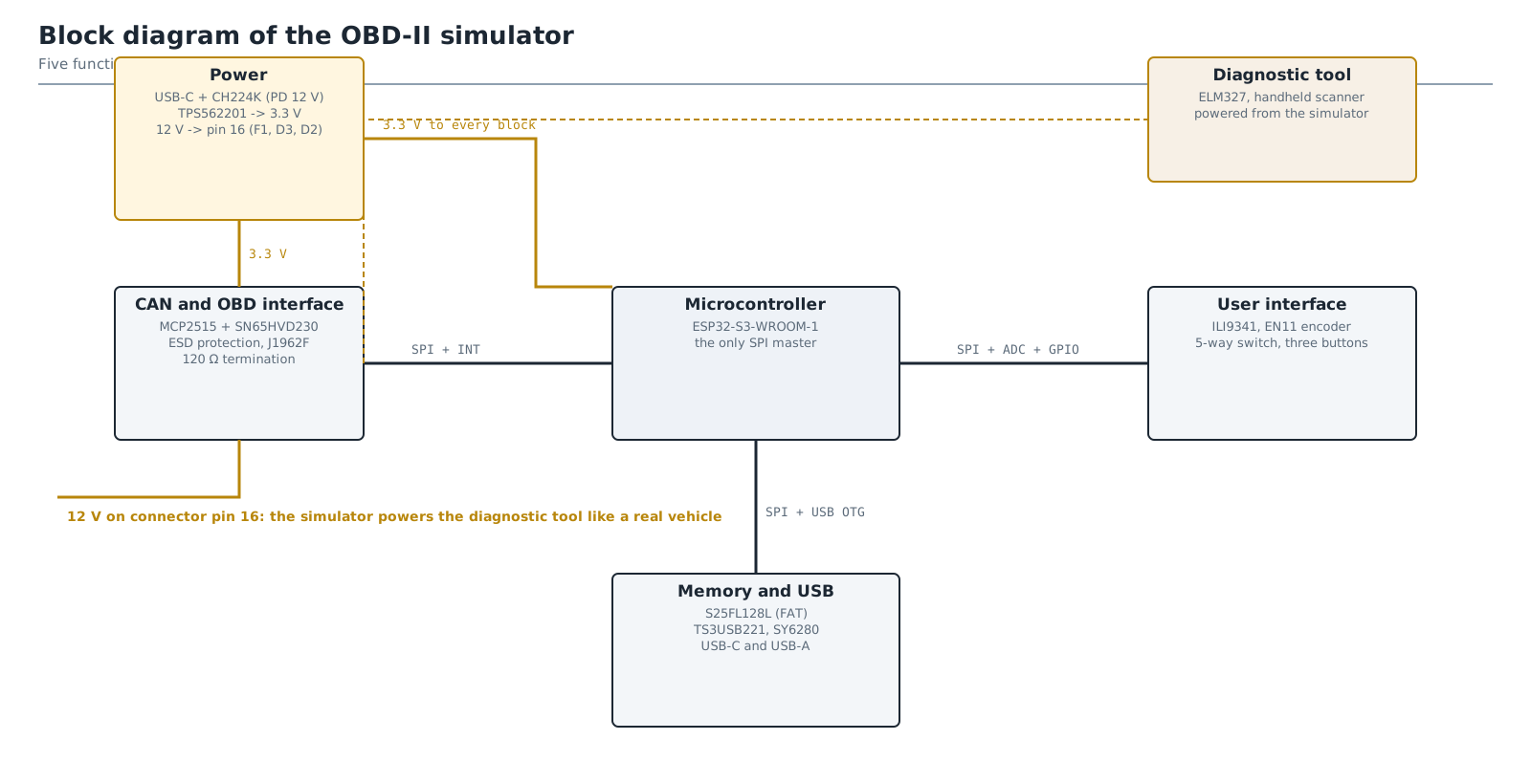
The simulator answers a diagnostic tool over CAN and, like a real vehicle, powers
it from pin 16 of the J1962 connector. The protocol core described below is what
runs inside the "Microcontroller" block, and everything around it is documented
in hardware/README.md, which walks through the same
schematics one design decision at a time.
Everything in the repository is in English. The project also keeps a set of Croatian working documents, which live outside it.
The v0.7 board has been fabricated and assembled in one unit. A commercial ELM327 adapter connects to it, reads all 21 parameters and the fault codes, and draws its own 12 V from pin 16 while doing so.
The project has a landing page at https://filipraic.github.io/obd2-simulator/, which is the short version of everything below: what the device does, what it is built from and where to get the files. Two things on it are worth opening even if the page itself is skipped, because neither can be shown in a README:
| Page | What it is |
|---|---|
| The user interface demo | the screens firmware/src/ui/screens/ draws on the display, redrawn in a browser and walked with the same encoder and joystick controls the device has, so the interface can be tried before anything is built |
| The interactive board view | the v0.7 board drawn in the browser, with the tracks, the ground pour, the vias, the pads and the components as five layers that switch on and off, and a tooltip on every part. Generated from obd2-simulator.kicad_pcb by hardware/kicad/scripts/generate_pcb_html.py |
The wiki is written for someone using or rebuilding the device. The files in
this repository are the record of how it was built and why. The wiki is in
English, which is the language of the project. A Croatian translation of the
same pages exists but is not published yet, and if it goes up it will take an
-HR suffix, leaving the page names below unchanged.
| Question | Wiki page | In this repository |
|---|---|---|
| What is this and what can it do | Home | this file |
| How do I build one | Building the device | hardware/README.md, and hardware/gerber/README.md before ordering |
| How do I compile and flash it | Firmware | firmware/README.md, and firmware/tools/README.md when the ordinary upload path is unavailable |
| How do I drive it | Usage | scenarios/README.md for the JSON format |
| How do I contribute | Contributing | the conventions below |
| How is the board generated | - | hardware/kicad/scripts/README.md |
Two internal documents govern changes to this project, and neither is published
here: docs/MAPA-POVEZANIH-DATOTEKA.md is an "if you change X, check Y" table,
because the same fact is written down in up to six places, and
docs/combined/DNEVNIK-IZMJENA.md is the chronological record of every decision.
Both are in Croatian and are working notes rather than product documentation, so
docs/ is deliberately left out of the repository.
| File | Purpose |
|---|---|
include/obd2_pids.h | Mode/PID constants per SAE J1979 / ISO 15031-5 |
include/sensor_table.h | 21 simulated parameters with ranges and noise |
src/pid_encoder.cpp | Value → raw bytes codec + supported-PID bitmasks |
include/dtc_bank.h | DTC bank (pending/confirmed, MIL, freeze frame) |
src/iso_tp.cpp | ISO 15765-2 transmit path (SF, FF/FC/CF) |
src/can_handler.cpp | Request dispatcher, modes 0x01-0x09 |
src/simulator_core.cpp | Simulation profiles (Manual / Idle / Drive) |
tests/test_simulator.cpp | Host-side unit tests |
Implemented services: 0x01 (current data, 21 PIDs), 0x02 (freeze frame),
0x03/0x07 (stored/pending DTCs), 0x04 (clear DTCs), 0x09 (VIN).
Unsupported services receive the negative response 7F <mode> 11.
Requests are accepted on 0x7DF (functional) and 0x7E0 (physical), while
responses are sent on 0x7E8. Frames are padded to 8 bytes with 0x55
per ISO 15765-4.
uint32_t millis();                                // ms since boot
void     can_send_frame(const CanFrame& frame);   // MCP2515 transmit
bool     iso_tp_wait_flow_control(FlowControl&);  // wait for FC frame
void iso_tp_delay_us(uint32_t us); // STmin pacingcmake -B build
cmake --build build
ctest --test-dir build --output-on-failureThe same tests also run through PlatformIO (pio test -e native inside
firmware/). Firmware build: pio run -e custom-board (the dedicated
ESP32-S3 board, also used on the breadboard adapter during development).
The board is generated rather than drawn: there is no .kicad_sch, and the
.kicad_pcb is an output. Two entry points, and picking the wrong one costs
work:
# a part, a net or the placement changed - rebuilds and re-routes from nothing
powershell -ExecutionPolicy Bypass -File hardware\kicad\scripts\route_board.ps1

# the board file is already right, only the derived files are stale
powershell -ExecutionPolicy Bypass -File hardware\kicad\scripts\regen_outputs.ps1
route_board.ps1 ends by recomputing all 103 reference designator positions and
so discards the hand-tuned silkscreen. If no copper moved, run only
regen_outputs.ps1. Every step of the chain, what it writes and where, is in
hardware/kicad/scripts/README.md.
| Qty | Value | Footprint | References |
|---|---|---|---|
| 16 | 10k | R_Axial_DIN0207_L6.3mm_D2.5mm_P10.16mm_Horizontal | R9, R10, R11, R12, R13, R14, R15, R22, R28, R29, R32, R33, R34, R35, R36, R37 |
| 12 | 100nF | C_Disc_D5.0mm_W2.5mm_P5.00mm | C10, C11, C12, C13, C14, C15, C16, C20, C21, C23, C24, C29 |
| 5 | 10uF | CP_Radial_D5.0mm_P2.00mm | C5, C18, C19, C25, C37 |
| 4 | 22uF LowESR | CP_Radial_D6.3mm_P2.50mm | C3, C4, C27, C28 |
| 4 | M3 | MountingHole_3.2mm_M3 | H1, H2, H3, H4 |
| 3 | 100R | R_Axial_DIN0207_L6.3mm_D2.5mm_P5.08mm_Vertical | R38, R39, R40 |
| 3 | 1nF | C_Disc_D4.3mm_W1.9mm_P5.00mm | C34, C35, C36 |
| 3 | 33R | R_Axial_DIN0207_L6.3mm_D2.5mm_P10.16mm_Horizontal | R8, R30, R31 |
| 3 | 47nF | C_Disc_D5.0mm_W2.5mm_P5.00mm | C31, C32, C33 |
| 3 | 6k8 | R_Axial_DIN0207_L6.3mm_D2.5mm_P10.16mm_Horizontal | R19, R26, R27 |
| 2 | 1uF | C_Disc_D6.0mm_W2.5mm_P5.00mm | C22, C26 |
| 2 | 22pF | C_Disc_D4.3mm_W1.9mm_P5.00mm | C6, C7 |
| 2 | 4u7H | L_Radial_D8.7mm_P5.00mm_Fastron_07HCP | L2, L3 |
| 2 | 51k | R_Axial_DIN0207_L6.3mm_D2.5mm_P10.16mm_Horizontal | R16, R24 |
| 2 | SMAJ16A | D_SMA | D2, D3 |
| 2 | TPS562201DDCR | SOT-23-6 | U2, U11 |
| 2 | USBLC6-2SC6 | SOT-23-6 | D4, D5 |
| 1 | 100uF/25V | CP_Radial_D6.3mm_P2.50mm | C1 |
| 1 | 120R | R_Axial_DIN0207_L6.3mm_D2.5mm_P10.16mm_Horizontal | R7 |
| 1 | 15k | R_Axial_DIN0207_L6.3mm_D2.5mm_P10.16mm_Horizontal | R17A |
| 1 | 1k | R_Axial_DIN0207_L6.3mm_D2.5mm_P10.16mm_Horizontal | R21 |
| 1 | 24k | R_Axial_DIN0207_L6.3mm_D2.5mm_P10.16mm_Horizontal | R23 |
| 1 | 3V3 | TestPoint_THTPad_2.0x2.0mm_Drill1.0mm | TP1 |
| 1 | 470R | R_Axial_DIN0207_L6.3mm_D2.5mm_P10.16mm_Horizontal | R17B |
| 1 | 8MHz | Crystal_HC49-U_Vertical | Y1 |
| 1 | 9k31 | R_Axial_DIN0207_L6.3mm_D2.5mm_P10.16mm_Horizontal | R25 |
| 1 | BOOT | SW_PUSH_6mm | SW4 |
| 1 | CANH | TestPoint_THTPad_2.0x2.0mm_Drill1.0mm | TP3 |
| 1 | CANL | TestPoint_THTPad_2.0x2.0mm_Drill1.0mm | TP4 |
| 1 | CH224K | CH224K_ESSOP-10-1EP_3.9x5.0mm_P1mm_EP2.3x3.2mm | U1 |
| 1 | CLEAR | SW_PUSH_6mm | SW2 |
| 1 | CONFIRM | SW_PUSH_6mm | SW1 |
| 1 | EN11-HSB1AQ20 | RotaryEncoder_Alps_EC11E-Switch_Vertical_H20mm | ENC1 |
| 1 | ESP32-S3-WROOM-1 | ESP32-S3-WROOM-1 | U6 |
| 1 | GND | TestPoint_THTPad_2.0x2.0mm_Drill1.0mm | TP2 |
| 1 | J1962F OBD-II | SEP-A-OBD-D2 | J2 |
| 1 | LCD 18366 | PinHeader_1x08_P2.54mm_Vertical | J5 |
| 1 | MCP2515-I/SO | SOIC-18W_7.5x11.6mm_P1.27mm | U4 |
| 1 | MISO | TestPoint_THTPad_2.0x2.0mm_Drill1.0mm | TP6 |
| 1 | MOSI | TestPoint_THTPad_2.0x2.0mm_Drill1.0mm | TP5 |
| 1 | PESD1CAN | SOT-23 | D1 |
| 1 | PTC 500mA | Fuse_1206_3216Metric | F1 |
| 1 | RESET | SW_PUSH_6mm | SW5 |
| 1 | RETURN | SW_PUSH_6mm | SW3 |
| 1 | S25FL128LAGMFM010 | SOIC-8_5.3x5.3mm_P1.27mm | U7 |
| 1 | SCK | TestPoint_THTPad_2.0x2.0mm_Drill1.0mm | TP7 |
| 1 | SKRHABE010 | SKRHABE010 | SW6 |
| 1 | SN65HVD230DR | SOIC-8_3.9x4.9mm_P1.27mm | U5 |
| 1 | SY6280AAC | SOT-23-5 | U10 |
| 1 | TS3USB221 | Texas_DRC0010J | U9 |
| 1 | UART | PinHeader_1x03_P2.54mm_Vertical | J6 |
| 1 | USB-A | USB_A_Molex_67643_Horizontal | J4 |
| 1 | USB-C | USB_C_Receptacle_GCT_USB4085 | J1 |
| 1 | VBUS | TestPoint_THTPad_2.0x2.0mm_Drill1.0mm | TP8 |
It measures 130 × 115 mm and has 2 copper layers, 1.6 mm thick.
107 parts, built around the ESP32-S3-WROOM-1-N8, SN65HVD230DR, CH224K and S25FL128LAGMFM010. The full list of its parts is on this page, with links to each part's symbol and footprint where PCBKit's library has them.
From the FilipRaic/obd2-simulator repository on GitHub, at the commit this page was made from: the board is hardware/kicad/obd2-simulator.kicad_pcb. PCBKit opens the board in the browser, with nothing to install.
Its repository publishes it under the MIT licence: you may reuse it on that licence's terms (keep the author's notice, and for a copyleft licence share your changes alike).

WestianPKl/pcb-docs
A collection of custom PCB designs created in KiCAD, centered around the Raspberry Pi Pico (RP2040) platform. Each board is a standalone module that connects to the Main Board and extends its functionality via I2C, SPI…


Kilan777/HomeDeck
Jarvis HomeDeck: a Raspberry Pi CM4 carrier board and voice-assistant software for a 7-inch smart display (KiCad hardware, generated from Python, plus the Python/JS assistant)


NewTec-GmbH/esp32-can-iot
A ESP32 based interface between CAN-bus and IoT environments.

cUDGk/vrc-fbt-hardware
VRChat向けフルボディトラッキング基板 — ハブ+デイジーチェーン端末・数と位置を自由に変更可能・KiCad/OpenSCAD一式