2 layers229.9 × 93.3 mm
 ethanjamesauto/modular_8bit_computer2
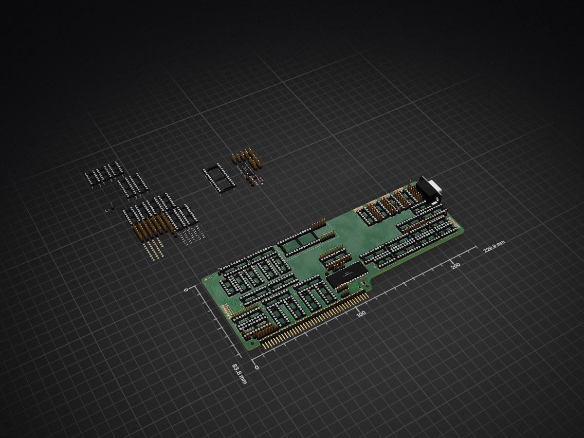
Processor attempt 4 is an open-source printed circuit board by ethanjamesauto, from the ethanjamesauto/modular_8bit_computer repository on GitHub. It is a 2-layer board of 229.9 × 83.8 mm with 352 parts on 516 nets, routed with 3,123 tracks and 169 vias.
It is built around the A13, 74LS245SC and 74LS367PC, with the 74LS273PC, 74LS161DC and 74LS00SC among its other parts. Its parts include 121 resistors, 114 diodes, 61 connectors, 51 ICs and 2 capacitors.


This is the repository for an 8-bit computer system that is built using cards with a standardized interface.
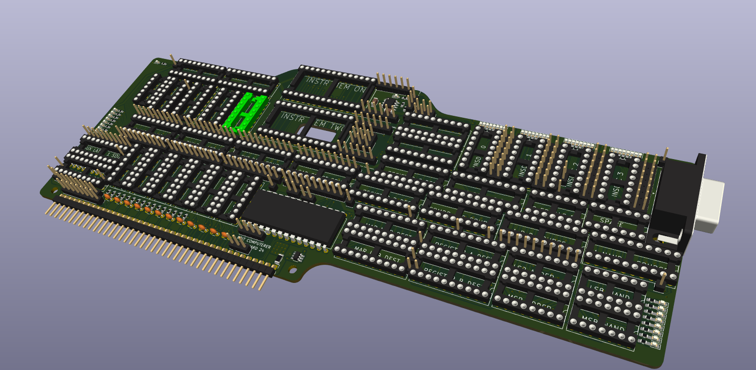
Here's an example of a card:
// The main bus wires (32+8=40 wires total)
// On the bus connector, all buses have LSBs closer to the power pins and MSBs farther away
wire VCC_5V;
wire GND;
wire clk;			      // generated by motherboard clock generator
wire rst_n;			    // probably a button on the motherboard
wire VCC_3V3;
wire we_n;			      // active LOW
wire oe_n;			      // active LOW
wire int_n;			    // pulled up by motherboard; driven down by any peripheral (could be used for interrupts)
wire [7:0] data;
wire [15:0] addr;	  // 64k address space is suppored by default. More address bits may be added later
wire [7:0] aux_bus;| Qty | Value | Footprint | References |
|---|---|---|---|
| 106 | 470 | Resistor_SMD:R_0603_1608Metric_Pad0.98x0.95mm_HandSolder | r107, r108, r109, r110, r110, r111, r111, r112, r112, r113, r113, r114, r114, r115, r115, r116 +90 |
| 69 | A0 | LED_SMD:LED_0603_1608Metric_Pad1.05x0.95mm_HandSolder | D1, D17, D25, D33, D41, D49, D49, D50, D50, D51, D51, D52, D52, D53, D53, D54 +53 |
| 23 | J | Connector_PinHeader_2.54mm:PinHeader_1x01_P2.54mm_Vertical | J36, J37, J41, J43, J44, J46, J47, J48, J49, J50, J51, J52, J57, J60, J62, J64 +7 |
| 17 | Conn_01x08_Pin | Connector_PinHeader_2.54mm:PinHeader_1x08_P2.54mm_Vertical | J4, J20, J22, J22, J23, J24, J24, J25, J25, J26, J26, J27, J28, J28, J29, J29 +1 |
| 12 | 0 | Resistor_SMD:R_0603_1608Metric_Pad0.98x0.95mm_HandSolder | R107, R108, R109, R118, R119, R120, R129, R130, R141, R142, R145, R146 |
| 9 | 74LS273 | Package_DIP:DIP-20_W7.62mm_Socket | U6, U7, U24, U27, U37, U40, U41, U44, U45 |
| 7 | 74LS138 | Package_DIP:DIP-16_W7.62mm_Socket | U36, U57, U58, U58, U59, U59, U60 |
| 7 | 74LS245 | Package_DIP:DIP-20_W7.62mm_Socket | U21, U23, U29, U30, U31, U49, U50 |
| 6 | A4 | LED_SMD:LED_0603_1608Metric_Pad1.05x0.95mm_HandSolder | D5, D21, D29, D37, D45, D82 |
| 6 | Conn_01x03_Pin | Connector_PinHeader_2.54mm:PinHeader_1x03_P2.54mm_Vertical | J1, J31, J32, J33, J34, J69 |
| 5 | A1 | LED_SMD:LED_0603_1608Metric_Pad1.05x0.95mm_HandSolder | D2, D18, D26, D34, D42 |
| 5 | A2 | LED_SMD:LED_0603_1608Metric_Pad1.05x0.95mm_HandSolder | D3, D19, D27, D35, D43 |
| 5 | A3 | LED_SMD:LED_0603_1608Metric_Pad1.05x0.95mm_HandSolder | D4, D20, D28, D36, D44 |
| 5 | A5 | LED_SMD:LED_0603_1608Metric_Pad1.05x0.95mm_HandSolder | D6, D22, D30, D38, D46 |
| 5 | A6 | LED_SMD:LED_0603_1608Metric_Pad1.05x0.95mm_HandSolder | D7, D23, D31, D39, D47 |
| 5 | A7 | LED_SMD:LED_0603_1608Metric_Pad1.05x0.95mm_HandSolder | D8, D24, D32, D40, D48 |
| 4 | 74LS161 | Package_DIP:DIP-16_W7.62mm_Socket | U2, U3, U4, U5 |
| 4 | 74LS367 | Package_DIP:DIP-16_W7.62mm_Socket | U38, U47, U48, U51 |
| 4 | Conn_01x01_Pin | Connector_PinHeader_2.54mm:PinHeader_1x01_P2.54mm_Vertical | J30, J35, J40, J42 |
| 4 | Conn_01x06_Pin | Connector_PinHeader_2.54mm:PinHeader_1x06_P2.54mm_Vertical | J14, J15, J16, J17 |
| 4 | Conn_01x10_Pin | Connector_PinHeader_2.54mm:PinHeader_1x10_P2.54mm_Vertical | J8, J18, J19, J19 |
| 3 | R | Resistor_SMD:R_0603_1608Metric_Pad0.98x0.95mm_HandSolder | R1, R2, R142 |
| 2 | 28C256 | Package_DIP:DIP-28_W15.24mm_Socket | U18, U19 |
| 2 | 74LS00 | Package_DIP:DIP-14_W7.62mm_Socket | U52, U53 |
| 2 | 74LS04 | Package_DIP:DIP-14_W7.62mm_Socket | U42, U56 |
| 2 | 74LS283 | Package_DIP:DIP-16_W7.62mm_Socket | U32, U39 |
| 2 | 74LS30 | Package_DIP:DIP-14_W7.62mm_Socket | U35, U55 |
| 2 | 74LS32 | Package_DIP:DIP-14_W7.62mm_Socket | U33, U34 |
| 2 | 74LS574 | Package_DIP:DIP-20_W7.62mm_Socket | U25, U26 |
| 2 | C | Capacitor_SMD:C_1206_3216Metric | C1, C2 |
| 1 | 1 | Resistor_SMD:R_1206_3216Metric | 5V_rsns1 |
| 1 | 10k | Resistor_SMD:R_1206_3216Metric | 5V_rsns2 |
| 1 | 5V_RAW | LED_SMD:LED_0603_1608Metric_Pad1.05x0.95mm_HandSolder | D81 |
| 1 | 74HC688 | Package_DIP:DIP-20_W7.62mm_Socket | U43 |
| 1 | 74LVC1G08 | Package_TO_SOT_SMD:SOT-23-6_Handsoldering | U61 |
| 1 | A10 | LED_SMD:LED_0603_1608Metric_Pad1.05x0.95mm_HandSolder | D11 |
| 1 | A11 | LED_SMD:LED_0603_1608Metric_Pad1.05x0.95mm_HandSolder | D12 |
| 1 | A12 | LED_SMD:LED_0603_1608Metric_Pad1.05x0.95mm_HandSolder | D13 |
| 1 | A13 | LED_SMD:LED_0603_1608Metric_Pad1.05x0.95mm_HandSolder | D14 |
| 1 | A14 | LED_SMD:LED_0603_1608Metric_Pad1.05x0.95mm_HandSolder | D15 |
| 1 | A15 | LED_SMD:LED_0603_1608Metric_Pad1.05x0.95mm_HandSolder | D16 |
| 1 | A8 | LED_SMD:LED_0603_1608Metric_Pad1.05x0.95mm_HandSolder | D9 |
| 1 | A9 | LED_SMD:LED_0603_1608Metric_Pad1.05x0.95mm_HandSolder | D10 |
| 1 | Clock_Aux_Latch_0 | Connector_PinHeader_2.54mm:PinHeader_1x01_P2.54mm_Vertical | J39 |
| 1 | Conn_01x40_Pin | Connector_PinHeader_2.54mm:PinHeader_1x40_P2.54mm_Horizontal | J3 |
| 1 | DB9_Female_MountingHoles | Connector_Dsub:DSUB-9_Female_Horizontal_P2.77x2.84mm_EdgePinOffset4.94mm_Housed_MountingHolesOffset7.48mm | J21 |
| 1 | HM62256BLP | Package_DIP:DIP-28_W15.24mm | U28 |
| 1 | HM62256BLP | Package_SO:SOIC-28W_7.5x18.7mm_P1.27mm | U46 |
| 1 | LOGO | AudioJacks:plant | G*** |
| 1 | NE555D | Package_SO:SOIC-8_3.9x4.9mm_P1.27mm | U1 |
| 1 | ~ | Package_DIP:DIP-16_W7.62mm_Socket | U62 |
It measures 229.9 × 83.8 mm and has 2 copper layers, 1.6 mm thick.
352 parts, built around the A13, 74LS245SC, 74LS367PC and 74LS273PC. The full list of its parts is on this page, with links to each part's symbol and footprint where PCBKit's library has them.
From the ethanjamesauto/modular_8bit_computer repository on GitHub, at the commit this page was made from: the board is processor_attempt_4/processor_attempt_4.kicad_pcb. PCBKit opens the board in the browser, with nothing to install.
Its repository states no licence, so its author keeps all rights: ask ethanjamesauto before reusing the design.


RichCini/LomasBoards
Small repository of files/data related to Lomas Data Products S-100 boards.

Jipxmaster/Canned-ICs-1.2
"Chips Enlatados" es un proyecto en la que intento colocar el mayor número de integrados de la serie 7400 en el menor espacio posible.

RetroStack/TRS-80-Model-I-Expansion-Interface-Rev-D
Hardware Replica of the TRS-80 Model I Expansion Interface - Revision D

flypie/Ace-2019
Reimplimentation of the Jupiter ACE with slightly more modern hardware. https://www.jupiter-ace.co.uk/ the KiCad versions are the up to date designs which are available at https://jupiterdeuce.blogspot.com and…


roberto314/GIMIX_reproduction
Reproducing SS-50 and SS-30 cards and GIMIX Ghost Case and Mainboard
