CNC Pendant - Wireless Controller for Genmitsu 4040 CNC Mill
Note: This is a work in progress. The project is under active development and contributions are welcome! If you're interested in helping with the firmware, hardware design, or adding support in CNC control software, please feel free to reach out or submit pull requests.
Project Description
CNC Pendant is a peripheral device based on ESP8266 that serves as a wireless controller for the Genmitsu 4040 CNC mill. The device allows for controlling the machine axes, monitoring the machine state, and executing basic control operations through a touch interface and rotary knob.
This project was designed with simplicity and practicality in mind, focusing on essential functions like jogging and basic machine control (start/stop/pause) rather than attempting to replicate all CNC controller features.
The entire project, including electronics design, firmware development, and 3D-printed enclosure, is original work (excluding the ESP8266 module and display components).
Hardware Specifications
- Main Processor: ESP8266EX
- Display: 3.2" Capacitive Touch Screen (240x320 pixels) - Product Link
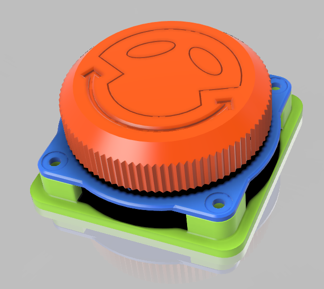
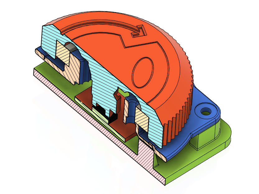
- Control Knob: AS5600 magnetic encoder
- Communication: WiFi (wireless) and USB options
- Power: Currently USB-powered with plans for battery operation in future versions
- Configuration Storage: External I2C EEPROM
- Other Components: PCA9536 controller (pin management), physical buttons
- Enclosure: Custom 3D-printed case
Hardware & Screenshots
Physical Hardware
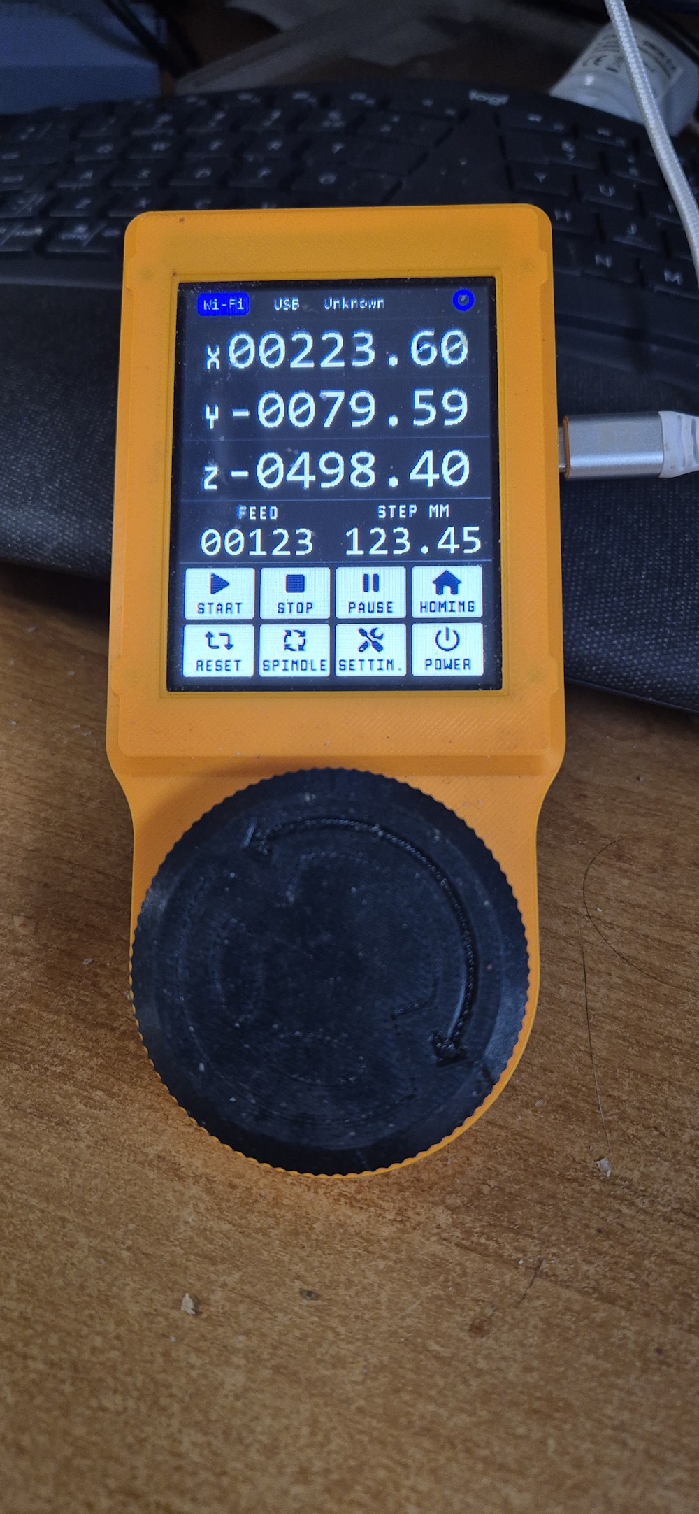
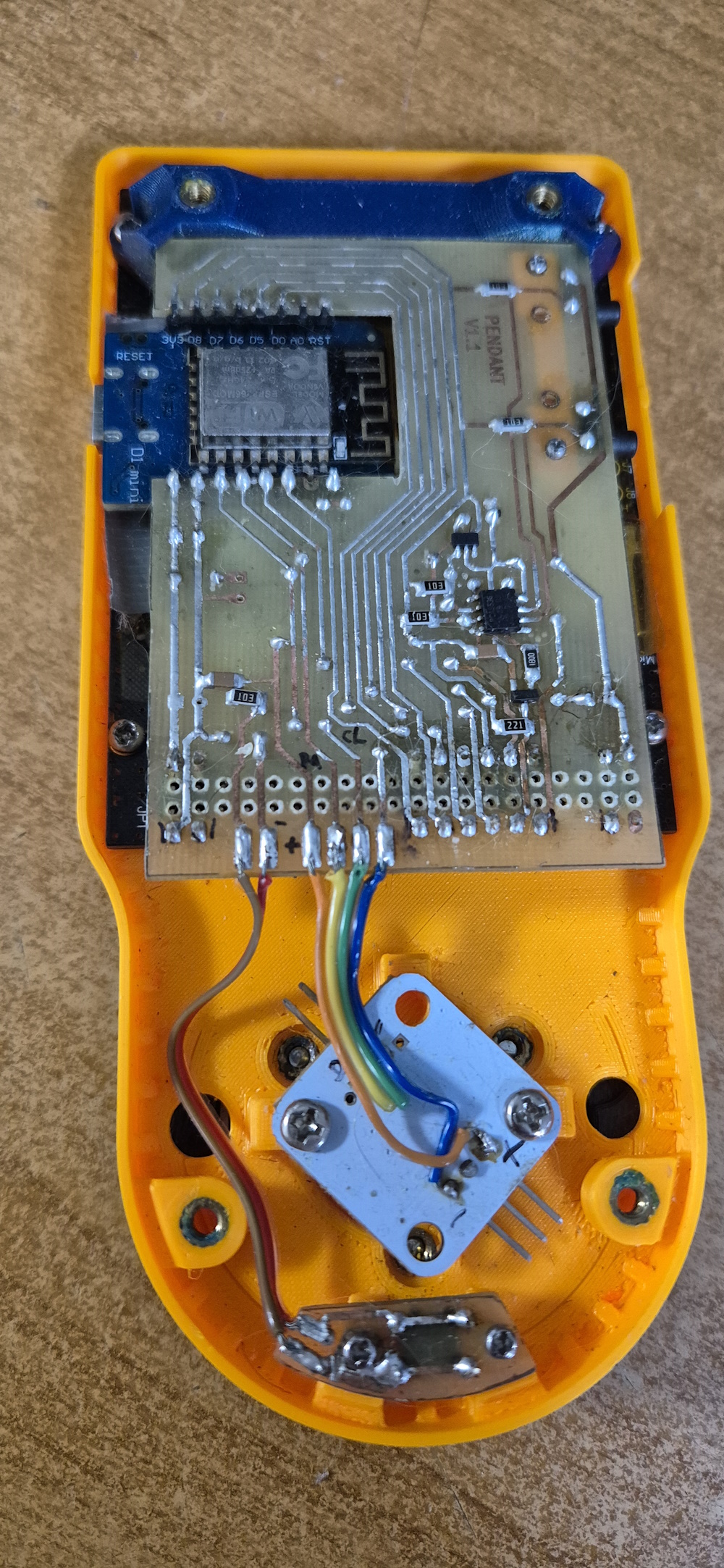
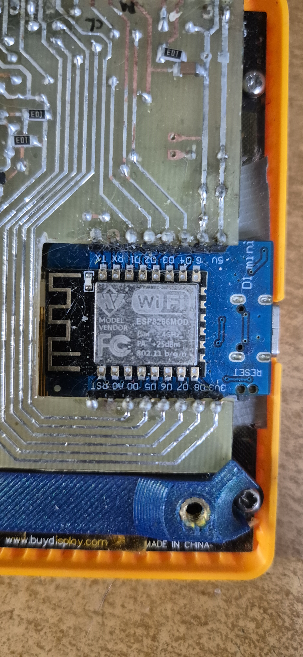
Interface Screenshots
Functionality & Controls
The pendant focuses on delivering essential CNC control functions in a user-friendly package:
Primary Features
- Axis Jogging: Control machine movement using the physical rotary knob after selecting an axis
- Basic Machine Control: Start, stop, and pause operations directly from the pendant
- Status Monitoring: View machine status and position information on the display
Control Interface
- Touch Screen: Most functions are accessible through the touch interface
- Rotary Knob: Provides precise control for axis jogging
- Physical Buttons:
- Three dedicated buttons for quick feed/step value selection (added based on user testing for speed of operation)
- Additional button beneath the knob intended for emergency stop functionality
Main Software Modules
1. Communication Module (WirelessCommunicator)
- Handles WiFi communication between the pendant and the CNC controller
- Implements TCP protocol for data exchange
- Handles buffering and error checking (CRC)
- Maintains connection and detects connection loss
2. State Module (State)
- Tracks current axis positions (X, Y, Z)
- Monitors CNC machine state (idle, alarm, running, etc.)
- Provides data to the user interface
3. User Interface (Screen, MainPage, Drawable)
- Displays the interface with current machine status
- Handles touch interactions
- Shows status indicators (WiFi, machine state, etc.)
- Implements axis control widget
4. Knob Control (Wheel)
- Reads rotations from the AS5600 magnetic encoder
- Provides direction and speed data
- Works in conjunction with active axis selection for control
5. Configuration Management (ConfigManager)
- Saves and loads configuration from EEPROM memory
- Stores WiFi settings, server address, and other parameters
- Handles default configuration when no saved settings are found
6. Event Handling (EventManager)
- Central event handling system
- Allows communication between modules through event system
- Handles button events, state updates, WiFi connection changes
7. Button and Touch Screen Handling (Touch, Buttons)
- Reads touch from the FT6206 controller
- Handles physical buttons
- Maps touch events to appropriate actions
Communication Options
The device offers two connectivity options:
- WiFi communication: Primary wireless connection method
- USB communication: Alternative connection option
Currently, the pendant requires USB power regardless of the selected communication method. Future plans include adding battery power support, although power consumption of the LCD display is a concern that needs to be addressed.
Communication Protocol
The device communicates with the CNC controller using a custom TCP/IP-based protocol that includes:
- Packets with an identification header (0xAA55)
- Various message types (state, configuration, ping)
- CRC verification to ensure data integrity
Development Environment
The project was created using:
- Arduino Framework
- PlatformIO as the development environment
- Libraries: Adafruit ILI9341, Adafruit GFX, ESPAsyncTCP, and others
Technical Implementation Details
Performance Optimization
The firmware was heavily optimized to work efficiently on the relatively modest ESP8266 platform, which was an intentional choice for this project. Key optimization strategies include:
- Hardware-Accelerated Graphics: Code leverages the hardware capabilities of both the processor and display wherever possible
- Efficient UI Rendering: Custom drawing procedures to avoid full-screen redraws
- Partial Screen Updates: When popup windows appear, the underlying interface remains active
- Clipping Algorithms: Text and elements that would be covered by overlays are efficiently clipped rather than redrawn
- Memory-Conscious Design: Due to RAM limitations, buffer-based rendering techniques were avoided in favor of direct drawing
The UI design makes specific technical compromises (such as full-width popup windows) to enable these optimizations, prioritizing performance and responsiveness over visual complexity.
Compatibility & Support
This pendant is a custom device and currently does not have standard support in any commercial CNC control software or hardware. Development is underway to add support in the Candle CNC control program.
Testing Tools
- Windows simulator/debugger for development without hardware
- Hercules (TCP testing software)
- TcpTerminal
Windows Simulator
A Windows simulator is included for development and testing without hardware. The simulator is based on Qt (tested with Qt 6.9.1 on Windows). To run the simulator, simply open the Pendant.pro file in QtCreator and build the project—no special configuration should be required.
Contributing
Contributions to this project are welcome! Whether you're interested in:
- Adding new features to the firmware
- Improving the hardware design
- Creating support in additional CNC control software
- Optimizing performance
- Improving documentation
Feel free to fork the repository, make your changes, and submit a pull request. For major changes or new feature ideas, please open an issue first to discuss what you would like to change.


