4 layers100 × 60 mm

 EPSILON0-dev/Raven11064
Raspberry Pi-style SBC based on the Rockchip RV1106G3
Rv1106 is an open-source printed circuit board by EPSILON0-dev, from the EPSILON0-dev/Raven1106 repository on GitHub. It is a 4-layer board of 86 × 56 mm with 217 parts on 243 nets, routed with 2,042 tracks and 415 vias.
It is built around the RV1106G3, PAM2306AYPAA and CH334F, with the EA3036CQBR, ESP32-C6-MINI-1 and FSUSB42MUX among its other parts. Its parts include 89 capacitors, 77 resistors, 8 ICs, 8 connectors and 7 diodes. It belongs with the computers and single-board computers boards and the ESP32 and RISC-V boards of this library.


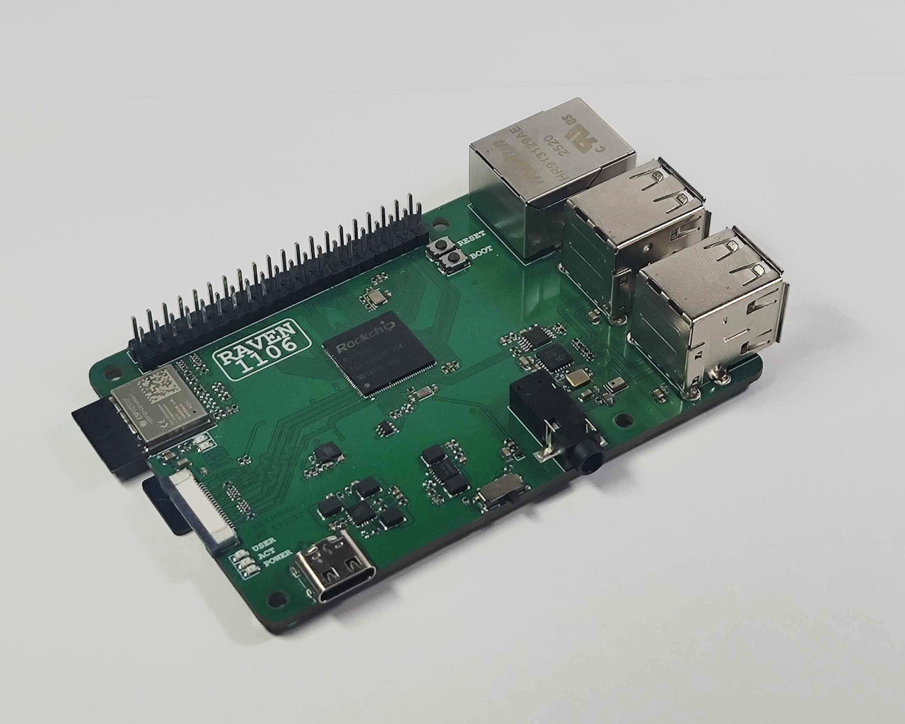
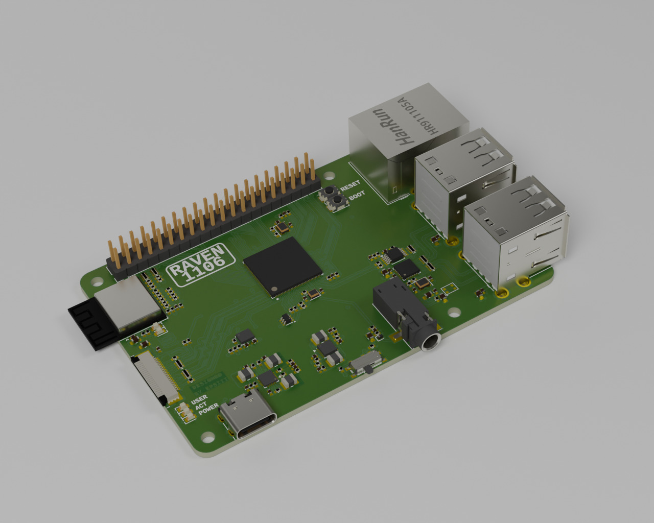
Raspberry Pi-like single board computer based on the Rockchip RV1106G3.
 |  |
|---|---|
Raven1106 is a custom open-hardware SBC. This repository contains everything related to the project including: the board schematics and the PCB design, build scripts, configurations, device trees and file system overlays for the operating system images and all the patches needed to get everything working.
TLDR: It's a learning project
The main goal of this project was to be a learning experience for designing complex high-speed digital PCBs. Creating an SBC that is almost capable enough to do basic tasks like hosting simple servers or running AI harnesses is a nice bonus. RV1106 was chosen specifically for its simplicity, integrated RAM meant no DDR routing and QFN package meant I could solder the board manually relatively easily.
What this chip lacked in the hardware it made up for in the software side of things -- BSP is absolutely terrible, outdated, barely documented (though with a lot of spelling mistakes). Programming it wasn't much better either with only a few barely working flashing tools and a USB controller that might not actually be compliant with the USB spec, as most machines can't even enumerate it. It might have been genuinely easier to make this project around a more complex BGA part than this SoC.
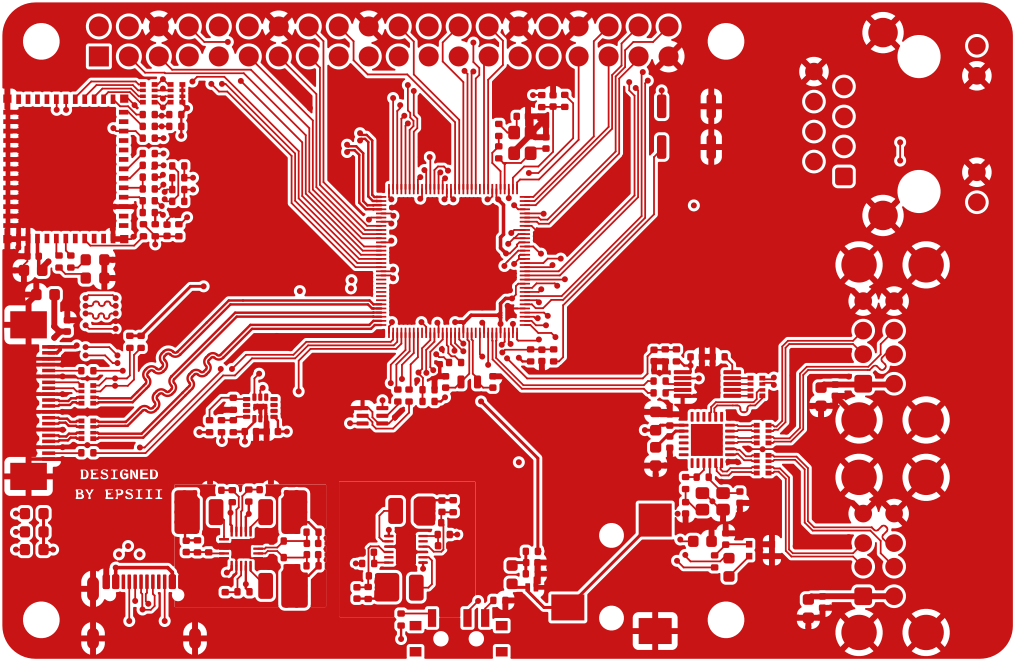
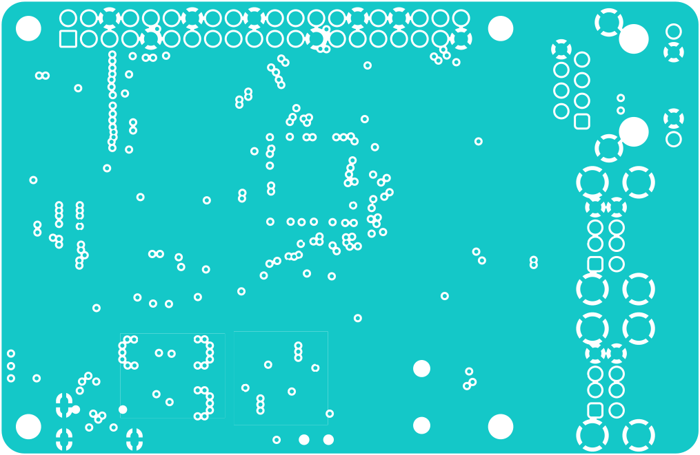
The board is designed in KiCad (4-layer). pcb/ contains two revisions:
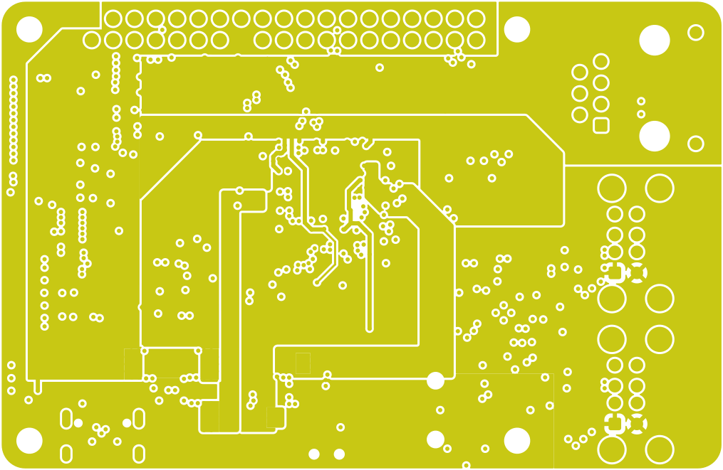
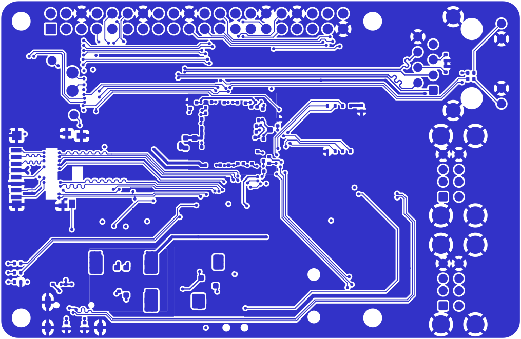
pcb/v1.0 — first revisionpcb/v1.1 — revision with component value fixes (no PCB layout changes)| Layer 1 - Signal | Layer 2 - Ground Plane | Layer 3 - Power Planes | Layer 4 - Signal |
|---|---|---|---|
 |  |  |  |
USB Impedance Miscalculation - Turns out that FSUSB42MUX doesn't act as a retransmitter but like a normal switch which adds ~10 ohm impedance to the line. Fix: Swap RN301 with 0-ohm and change R301 and R302 from 22 ohm to 10 ohm. This results the line impedance that is well in spec.
No pullups on FSPI Flash - Speaks for itself, thankfully the RV1106 has internal pull-ups that enable the chip and disable the write protection. And we don't even use it so it's a non-issue. Cannot fix this without board changes.
LED resistors too small - The LEDs shine too brightly with 1k resistors. Fix: Change R3, R4 and R5 from 1k to 10k resistors.
USB Hub crystal load too large - The CH334F is designed to work with a crystal with no load caps, adding them causes the oscillation to die down. Fix: Change R309 from 1k to 10 ohm, remove C302 and C303.
Boot button pull-up too strong - With 1k the button does not affect the chip's boot at all. Fix: Change R6 from 1k to 10k.
Wrong ESP_BOOT pin exposed - It should be pin 9, not pin 8. Fix: No way to fix it without modifying the board unfortunately, just flash the bootloader before soldering the ESP.
Reference clock not connected to the camera - Turns out not all camera modules have their own crystal oscillators. SC3336 requires a reference clock; RV1106 has two reference clock outputs, one of them is connected to the camera's reset and the other one to the IMU interrupt pin. Fix: Add a jumper from R508 to R515.
Most of these problems could have been prevented with "RTFM" (Reading The F***ing Manual).
| Path | Contents |
|---|---|
configs/ | Defconfigs (kernel, U-Boot, crosstool-ng), device tree source, SD image layout, U-Boot env, user table |
kernel/ | Linux 5.10 Rockchip BSP kernel |
uboot/ | U-Boot 2017.09 Rockchip BSP |
debian/, overlayfs/ | Debian rootfs staging area and overlay |
crosstool-ng/, legacy-toolchain/ | Legacy uClibc toolchain (kernel/U-Boot builds) |
esp-hosted/ | ESP32-C6 host driver source (esp_hosted_ng) |
rkbin/ | Rockchip binary blobs (DDR init, trust) |
scripts/build.sh | Image assembly, Debian rootfs, Docker environment |
images/ | Build artifacts and final sdcard.img |
pcb/ | KiCad hardware design |
docs/ | RV1106 datasheet / reference manuals |
All builds run inside a Docker container. The first invocation builds the
rv1106-build image, then drops you into a shell with the repository
mounted at /work:
make dockerBefore building any image build the legacy toolchain for the Kernel and U-Boot.
make toolchainmake # default target: debian-image
# or explicitly:
make debian-imageKnown issue: If build fails on stage 2 debootstrap because of "Invalid format", just delete the
debian/directory, restart the container and try to build again. It does that sometimes...
This builds the kernel, device tree, and U-Boot, then creates a Debian 12
(bookworm, armhf) rootfs with debootstrap (using qemu-user-static/binfmt for
the second stage) and assembles images/sdcard.img.
Notes:
debian, password raven (sudo user, SSH enabled).
Override with the BOARD_USER and DEBIAN_PASSWORD environment variables.DEBIAN_PACKAGES in
scripts/build.sh).DEBIAN_ROOTFS_SIZE).sudo resize2fs /dev/mmcblk1p5 after
the first boot.| Target | Description |
|---|---|
make kernel | Build the kernel using the legacy toolchain |
make dtb | Preprocess and compile configs/device-tree.dts into images/ |
make uboot | Build U-Boot (SPL + idblock + uboot.img) |
make espdriver | Build the ESP32-C6 host driver against the kernel |
make toolchain | Build the crosstool-ng uClibc toolchain |
make docker | Build/enter the Docker build environment |
make *-clean | Clean kernel / U-Boot build trees |
Each of these copies the stored defconfig from configs/, opens
menuconfig, and saves the result back to configs/:
make kernel-config
make uboot-config
make toolchain-configAll artifacts land in images/:
| File | Description |
|---|---|
sdcard.img | Final flashable SD card image |
download.bin, idblock.img, uboot.img | Bootloader stages |
Image, zImage, device-tree.dtb | Kernel and device tree |
env.img | U-Boot environment (from configs/image-env.txt) |
boot.vfat | FAT32 boot partition (kernel + dtb) |
rootfs.ext4, rootfs.tar | Root filesystem |
The image has no MBR/GPT; partitions are defined by the kernel command line
(blkdevparts, see configs/sdcard-image.cfg and configs/image-env.txt):
| Partition | Offset | Size | Contents |
|---|---|---|---|
| env | 0x0 | 32 KiB | U-Boot environment |
| idblock | 0x8000 | 512 KiB | Rockchip ID block (SPL) |
| uboot | 0x88000 | 256 KiB | U-Boot |
| boot | 4 MiB | 64 MiB | FAT32: kernel image + device tree |
| rootfs | 68 MiB | remainder | ext4 root filesystem |
sudo dd if=images/sdcard.img of=/dev/sdX bs=4M status=progress conv=fsyncSerial console: ttyFIQ0 at 115200 baud.
The WiFi interface (ESP32-C6 running ESP-Hosted firmware over SDIO) is set up
at boot on a running system, it is not configured during the image build. The
helper script overlayfs/usr/local/bin/start-network (installed on the image
at /usr/local/bin/start-network) performs the entire sequence:
/lib/modules/5.10.252/: the crypto primitives (libaes, libarc4,
ecc, ecdh_generic), bluetooth, the wireless stack (cfg80211) and
finally the ESP-Hosted SDIO host driver (esp32_sdio.ko). The script then
waits 5 s for the module to appear as wlan0.
(The host driver is built separately with make espdriver.)wpa_passphrase <ssid> <password> generates a config
into /tmp/wpa.conf and wpa_supplicant -iwlan0 is started in the
background, followed by a 15 s wait for the connection to come up.192.168.0.100/24 on wlan0 with the default route via 192.168.0.1.The SSID, passphrase and addresses are hardcoded in
/usr/local/bin/start-network, so edit them on the board (or in
overlayfs/usr/local/bin/start-network and rebuild/flash the image):
sudo vi /usr/local/bin/start-networkReplace ssid and password in the wpa_passphrase call with your network
name and passphrase, and adjust the ip addr add and ip route replace default via lines for your address and gateway. There is no DHCP client call
for wlan0.
The script runs automatically at boot via the systemd unit
overlayfs/etc/systemd/system/start-network.service
(/etc/systemd/system/start-network.service on the image) - a oneshot
service started after network.target, running as root with
RemainAfterExit=yes, and logging all output to /tmp/wifi.log. Use it to
start/stop the WiFi bring-up manually or to check the log:
sudo systemctl start start-network
sudo systemctl status start-network
less /tmp/wifi.log
Note: the ESP32 must already carry the ESP-Hosted firmware (flash the bootloader/ESP before soldering it, see the PCB section above).
| Qty | Value | Footprint | References |
|---|---|---|---|
| 44 | 100n | Capacitor_SMD:C_0402_1005Metric | C105, C107, C108, C124, C125, C129, C130, C132, C133, C134, C135, C136, C137, C138, C139, C140 +28 |
| 26 | 10u 6.3V | Capacitor_SMD:C_0603_1608Metric | C102, C103, C104, C109, C113, C114, C115, C116, C117, C118, C119, C122, C123, C126, C127, C131 +10 |
| 18 | 10k | Resistor_SMD:R_0402_1005Metric | R101, R103, R201, R313, R401, R406, R407, R408, R409, R420, R421, R501, R506, R507, R510, R511 +2 |
| 17 | 22 | Resistor_SMD:R_0402_1005Metric | R2, R205, R301, R302, R410, R411, R412, R413, R414, R415, R416, R417, R418, R419, R508, R515 +1 |
| 12 | 1k | Resistor_SMD:R_0402_1005Metric | R3, R4, R5, R6, R8, R303, R307, R308, R309, R311, R312, R403 |
| 7 | 100 | Resistor_SMD:R_0402_1005Metric | R7, R9, R402, R404, R503, R505, R509 |
| 6 | 18p | Capacitor_SMD:C_0402_1005Metric | C1, C2, C3, C4, C302, C303 |
| 6 | 22 | Resistor_SMD:R_Array_Convex_4x0402 | RN301, RN302, RN303, RN402, RN501, RN502 |
| 5 | 1u5 | Inductor_SMD:L_1008_2520Metric | L101, L102, L103, L104, L105 |
| 5 | 220p | Capacitor_SMD:C_0402_1005Metric | C110, C111, C112, C120, C121 |
| 4 | 100k 1% | Resistor_SMD:R_0402_1005Metric | R106, R107, R112, R113 |
| 4 | 1u | Capacitor_SMD:C_0402_1005Metric | C128, C153, C401, C508 |
| 4 | MountingHole | MountingHole:MountingHole_2.7mm_M2.5 | H1, H2, H3, H4 |
| 2 | 0 | Resistor_SMD:R_0402_1005Metric | R202, R502 |
| 2 | 100k | Resistor_SMD:R_0402_1005Metric | R102, R104 |
| 2 | 1M | Resistor_SMD:R_0402_1005Metric | R1, R310 |
| 2 | 47k 1% | Resistor_SMD:R_0402_1005Metric | R109, R114 |
| 2 | 5k1 | Resistor_SMD:R_0402_1005Metric | R304, R306 |
| 2 | DNP | Capacitor_SMD:C_0402_1005Metric | C101, C106 |
| 2 | USB_A_Stacked | Connector_USB:USB_A_Wuerth_61400826021_Horizontal_Stacked | J303, J304 |
| 1 | 0 (0603) | Resistor_SMD:R_0603_1608Metric | R117 |
| 1 | 10k | Resistor_SMD:R_Array_Convex_4x0402 | RN401 |
| 1 | 10n | Capacitor_SMD:C_0402_1005Metric | C6 |
| 1 | 127k 1% | Resistor_SMD:R_0402_1005Metric | R115 |
| 1 | 12MHz | Crystal:Crystal_SMD_2520-4Pin_2.5x2.0mm | Y301 |
| 1 | 18k | Resistor_SMD:R_0402_1005Metric | R314 |
| 1 | 1n | Capacitor_SMD:C_0402_1005Metric | C5 |
| 1 | 200k | Resistor_SMD:R_0402_1005Metric | R105 |
| 1 | 200k 1% | Resistor_SMD:R_0402_1005Metric | R110 |
| 1 | 240 1% | Resistor_SMD:R_0402_1005Metric | R116 |
| 1 | 24MHz 20ppm | Crystal:Crystal_SMD_2520-4Pin_2.5x2.0mm | Y2 |
| 1 | 32.768kHz | Crystal:Crystal_SMD_2012-2Pin_2.0x1.2mm | Y1 |
| 1 | 40.2k 1% | Resistor_SMD:R_0402_1005Metric | R111 |
| 1 | 6.04k 1% | Resistor_SMD:R_0402_1005Metric | R305 |
| 1 | 9.1k 1% | Resistor_SMD:R_0402_1005Metric | R108 |
| 1 | ACT | LED_SMD:LED_0603_1608Metric | D2 |
| 1 | AudioJack | Connector_Audio:Jack_3.5mm_CUI_SJ-3523-SMT_Horizontal | J501 |
| 1 | BAT60A | Diode_SMD:D_SOD-323 | D201 |
| 1 | Boot | Button_Switch_SMD:SW_Push_SPST_NO_Alps_SKRK | SW1 |
| 1 | CH334F | Package_DFN_QFN:QFN-24-1EP_4x4mm_P0.5mm_EP2.7x2.7mm | U303 |
| 1 | Camera | FPC_Connector:FPC_20_0.5mm_MP_BottomSide | J502 |
| 1 | EA3036CQB | Package_DFN_QFN:QFN-20-1EP_3x3mm_P0.4mm_EP1.65x1.65mm | U101 |
| 1 | ESP32-C6-MINI-1 | RF_Module:ESP32-C6-MINI-1 | U402 |
| 1 | ESP_Boot | TestPoint:TestPoint_Pad_D1.5mm | TP401 |
| 1 | ESP_LED0 | LED_SMD:LED_0603_1608Metric | D401 |
| 1 | ESP_LED1 | LED_SMD:LED_0603_1608Metric | D402 |
| 1 | ESP_Reset | TestPoint:TestPoint_Pad_D1.5mm | TP402 |
| 1 | ESP_USBM | TestPoint:TestPoint_Pad_D2.0mm | TP404 |
| 1 | ESP_USBP | TestPoint:TestPoint_Pad_D2.0mm | TP405 |
| 1 | FDG1024NZ | Package_TO_SOT_SMD:SOT-363_SC-70-6 | Q501 |
| 1 | FSUSB42MUX | Package_SO:MSOP-10_3x3mm_P0.5mm | U302 |
| 1 | Flash | Package_SON:WSON-8-1EP_8x6mm_P1.27mm_EP3.4x4.3mm | U202 |
| 1 | GPIO | Connector_PinHeader_2.54mm:PinHeader_2x20_P2.54mm_Vertical | J1 |
| 1 | HR913129AE | Connector_RJ:RJ45_Hanrun_HR911105A_Horizontal | J302 |
| 1 | LSM6DSR | Package_LGA:LGA-14_3x2.5mm_P0.5mm_LayoutBorder3x4y | U501 |
| 1 | MSM421ACT006 | Microphone:LGA4-1.9x2.8 | MIC501 |
| 1 | Micro_SD_Card_Det1 | Connector_Card:microSD_HC_Hirose_DM3D-SF | J201 |
| 1 | PAM2306AYPAA | Package_DFN_QFN:WDFN-12-1EP_3x3mm_P0.45mm_EP1.7x2.5mm | U102 |
| 1 | PESD3V3S1UL | Diode_SMD:D_SOD-882 | D501 |
| 1 | POWER | LED_SMD:LED_0603_1608Metric | D1 |
| 1 | RV1106G3 | library:Rockchip_QFN-128-1EP_12.3x12.3mm_P0.35mm_EP7x7mm | U1 |
| 1 | Reset | Button_Switch_SMD:SW_Push_SPST_NO_Alps_SKRK | SW2 |
| 1 | USB_C_Receptacle_USB2.0_14P | Connector_USB:USB_C_Receptacle_G-Switch_GT-USB-7010ASV | J301 |
| 1 | USB_Select | Button_Switch_SMD:SW_SPDT_PCM12 | SW301 |
| 1 | USER | LED_SMD:LED_0603_1608Metric | D3 |
It measures 86 × 56 mm and has 4 copper layers, 1.61 mm thick.
217 parts, built around the RV1106G3, PAM2306AYPAA, CH334F and EA3036CQBR. The full list of its parts is on this page, with links to each part's symbol and footprint where PCBKit's library has them.
From the EPSILON0-dev/Raven1106 repository on GitHub, at the commit this page was made from: the board is pcb/v1.0/rv1106.kicad_pcb and its schematic pcb/v1.0/rv1106.kicad_sch. PCBKit opens the board in the browser, with nothing to install.
Its repository states no licence, so its author keeps all rights: ask EPSILON0-dev before reusing the design.


offgridevices/offgrid-hardware
Open hardware from OffGrid Devices. One folder per board. CERN-OHL-S.

punkfab/pcb-corpus
235 real KiCad boards from open-source hardware repositories, prepared as a placement and routing benchmark

CRImier/MyKiCad
My KiCad boards. Can't be bothered uploading individually anymore, so here you go.


sekigon-gonnoc/mtch6102_breakout
Breakout board of MTCH6102, a 2D capacitive touch sensor, for DIY split keyboards with TRRS connectors.
