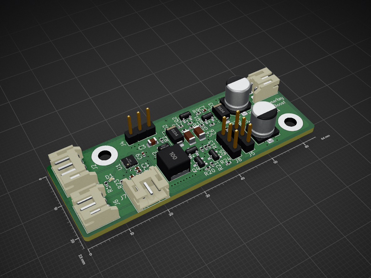
The consumer half of the ephemerkey system, and the second PCB in this repo (alongside hardware/ephemerkey/, sharing the same scripts/kschgen.py engine, Makefile, and lib tables — the multi-project layout used by…
Lock is an open-source printed circuit board by ephemerkey, from the ephemerkey/ephemerkey repository on GitHub. It is a 2-layer board of 64 × 23 mm with 50 parts on 35 nets, routed with 391 tracks and 106 vias.
It is built around the ATTINY1616-MN, MT3608 and AO3400A, with the RVT1E221M0607, SS34 and FNR6045S100MT among its other parts. Its parts include 20 resistors, 10 capacitors, 7 connectors, 5 transistors and 3 diodes. It belongs with the AVR (ATmega, ATtiny) boards of this library.
The consumer half of the ephemerkey system, and the second PCB in this
repo (alongside hardware/ephemerkey/, sharing the same scripts/kschgen.py
engine, Makefile, and lib tables — the multi-project layout used by
reefvolt-sensorbuddy). ephemerkey generates an authenticated unlock; this
board verifies it and drives the actuator.
text
make gen-lock      # regenerate the schematic from scripts/lock.schgen.py (placed, not wired)
make check-lock    # component/footprint/dup-ref/ERC tally
make render-lock   # per-sheet PNGs
The schematic is generated from a manifest (scripts/lock.schgen.py), like
ephemerkey. Components are placed, not wired — each sheet carries an
on-canvas note that is the wiring spec for the eeschema phase. Regenerate
before wiring (regen reassigns UUIDs).
What it does
Sleeps at ~0.1 µA (ATtiny1616 power-down). Coil de-energized, 12 V rail off.
ephemerkey starts an I2C transaction; the first START wakes the MCU (wake-on-I2C).
Authenticated challenge-response over I2C proves the request is
genuine (HMAC-SHA1, shared secret in flash — see Firmware plan).
On success: enable the boost, run the peak-and-hold solenoid profile,
then drop the rail and go back to sleep.
Everything (MCU + boost + driver) is powered from ephemerkey over the I2C
connector (J2.2 = VSYS, ephemerkey's ~3.0–4.7 V battery/system rail). The lock
carries no local battery (J1 removed). See the current caveat under the
interface section — a 12 V solenoid pull-in draws several amps through that cable.
* jlcsearch under-reports Basic flags; verify in JLCPCB's BOM tool at order time.
Every footprint is a KiCad-bundled package, so all parts carry 3D models — the
board is clearance-checkable in KiCad's 3D viewer once it's laid out.
Boost + reservoir sizing (read before ordering)
12 V × up to 1 A ≈ 12 W ≈ ~3.8 A from the cell — heavy. The design splits it:
The MT3608 is sized for the hold current (~0.3 A @ 12 V ≈ within its
~0.5 A @ 12 V capability) plus recharging the reservoir between actuations.
The reservoir (C5) supplies the brief pull-in surge. Sizing:
ΔV ≈ I_pull · t_pull / C. A 1 A, 30 ms pull-in pulls 30 mC; with 220 µF that
sags the rail a lot, so 220 µF is the baseline for ≤ ~500 mA / short
pull-ins. For a true sustained 1 A @ 12 V pull-in, either grow C5 into
the multi-thousand-µF range or swap the MT3608 for a TPS61088-class
boost that can source the full 12 W directly. Pin this down against the actual
solenoid's pull-in current × time and re-fire rate.
Set Vout exactly with the FB divider: Vout = 0.6·(1 + R3/R4). 200 k/10 k ≈
12.6 V; trim R3 toward 12.0 V if desired.
Servo variant + firmware actuator control
The board drives a 12 V solenoid or a 6 V RC servo. Because the boost
voltage and the servo power are both firmware-controlled, one fully-populated board
can carry both and switch between them (one actuator active at a time — a single
boost = a single voltage). Firmware drives three lines:
BOOST_VSEL (PA1) — picks the rail: low/default 6 V (servo-safe), high
12 V (solenoid). NMOS Q2 switches R17 across the FB divider.
SERVO_PWR_EN (PA2) — high-side P-FET (Q3) load switch on VSERVO. Servo power
comes on only when firmware asserts it and the boost is at 6 V: a hardware
interlock (Q5, gated by BOOST_VSEL) forces servo power OFF at 12 V regardless of
firmware, so a 12 V solenoid pulse can never reach a 6 V servo.
SERVO_SIG (PB2 / TCA0) — 50 Hz position pulse, via R15 (1 k) + R16 (10 k idle
pulldown) so the servo can't twitch at boot.
Mode
BOOST_VSEL
SERVO_PWR_EN
Actuator
Solenoid
12 V
off (interlock-forced)
Q1/D3/J3 peak-and-hold
Servo, 6 V
6 V
on
J5 servo, VSERVO ← VSOL (R13, populated)
Servo, direct
boost off
on
J5 servo, VSERVO ← VSYS (R14, DNP alt)
J5 / J8 — two 3-pin RC-servo outputs (1=SIG, 2=V+ (VSERVO), 3=GND), e.g. a
dual-latch lock. SERVO_SIG (PB2/TCA0) and SERVO_SIG2 (PB4, software-timed);
both share the VSERVO rail and the load-switch/interlock. MT3608 ~1 A @ 6 V —
drive them sequentially, or upsize C5/C8 for simultaneous travel.
VSERVO source — fit exactly one 0 Ω: R13 = VSOL (6 V from the boost —
the populated default) or R14 = VSYS (servo direct off the connector rail,
~3–4.7 V). Never both. C8 (220 µF) buffers servo inrush.
SERVO_SIG is VSYS-level logic (~3–4.7 V), accepted by typical servos, GND-referenced.
Authenticated digital interface + Firmware plan
The ephemerkey↔lock link is an authenticated I2C bus — ephemerkey is the
master, this lock is the target — on a right-angle 4-pin JST-PH (S4B-PH-K,
a standard 4-pin I2C cable, straight-through):
Pin
lock (this board, target)
ephemerkey (key, master)
1
GND (+ actuation return)
GND
2
VCC ← powers the lock (VSYS in)
VSYS (battery/system rail out)
3
SDA ↔ PB1
LOCK_SDA (PA6, I2C3)
4
SCL → PB0 (clock + wake)
LOCK_SCL (PA7, I2C3)
The lock has no local battery — its VCC (and the boost/actuator draw) comes in
on J2.2 from ephemerkey's VSYS rail. Current caveat: a 12 V solenoid pull-in is
~3–4 A from VSYS, beyond a JST-PH contact (~2 A) and ephemerkey's load-share path —
favor the 6 V servo / low-duty buffered by C5/C8, or run a heavier dedicated feed.
The I2C pull-ups live on ephemerkey at +3V3 (do not pull the bus to VSYS — the STM32
pins are 3.3 V-domain). The lock (running at VSYS) reads the 3.3 V idle
level fine across the discharge curve. The lock is the target at addr 0x60 with
no separate wake line — it wakes from power-down on the first I2C START (a
pin-change interrupt on SCL), so we don't mix a discrete "button"-style input with
the bus.
Authentication is firmware HMAC — no secure element. A pairing secret lives
in flash on both boards (separate from ephemerkey's TOTP secret).
I2C register/command map (lock = target @ 0x60). The master reads status/nonce
and writes authenticated commands:
Probe lid/door state (unauthenticated read — status only): the I2C START wakes
the lock; the master reads STATUS. DOOR_CLOSED / BOLT_LOCKED report the J6/J7
hall sensors; ACTUATOR tells the key whether a servo is fitted.
LOCK (0x02): servo → lock angle (a servo holds position). For a
momentary solenoid, LOCK is a no-op — it re-latches mechanically (fail-secure).
Master may re-read STATUS to confirm BOLT_LOCKED flipped.
code may be the ephemerkey TOTP digits, binding the action to a fresh in-fence
code. Optionally fold a monotonic counter (EEPROM) into the HMAC so a weak RNG
can't be exploited.
Lock firmware (ATtiny1616 — megaTinyCore or bare AVR):
State machine: SLEEP(power-down) → (I2C START wakes it) → service TWI as target
→ SLEEP; a verified COMMAND branches to ACTUATE. In SLEEP: TWI/boost off,
R6 holds Q1 off, R2 holds boost off; SCL (PB0) pin-change wakes it (wake-on-I2C).
STATUS read → pulse HALL_PWR (PA4) high, settle ~1 ms, sample HALL_DOOR
(PA7) + HALL_BOLT (PB3), drop HALL_PWR, return the bits (~0 µA between reads).
ACTUATE:
Solenoid — the peak-and-hold economizer: SOL_BOOST_EN=1 → wait VSOL →
SOL_PWM 100 % pull-in (~20–50 ms) → reduce duty for hold → release. PWM = TCB0 (PA5).
Servo — BOOST_VSEL=6 V, SERVO_PWR_EN=on, drive SERVO_SIG (PB2/TCA0) to
the lock/unlock angle, wait for travel, then cut servo power. The hardware
interlock keeps servo power off whenever BOOST_VSEL=12 V.
HMAC-SHA1 (reuse smalltotp, portable C → compiles for AVR) fits in 16 KB/2 KB.
Secret in USERROW/flash; disable UPDI / set lockbits in production.
Key firmware (ephemerkey STM32U083 — add to its superloop):
Probe the lid: wake the lock (I2C START) and read STATUS — surface door
open/closed + bolt locked/unlocked (e.g. on the OLED); no auth needed.
Lock / unlock: on a request (button + in-fence + fresh, valid TOTP), read
NONCE, compute HMAC-SHA1(secret, nonce ‖ cmd ‖ code), write COMMAND with cmd
= UNLOCK or LOCK. (Send a dummy/wake byte first and retry — the just-woken target
NACKs the first.) Re-read STATUS to confirm.
Use the same HMAC-SHA1 as the lock — smalltotp ships it, so both reuse it.
The pairing secret is provisioned over USB during pairing.
Programming
J4 UPDI header: 1 = UPDI (PA0), 2 = VCC (BAT), 3 = GND. One-wire UPDI via
pymcuprog, a serial-UPDI adapter, megaTinyCore, or Atmel-ICE/PICkit.
Bring-up checklist
Power from a current-limited 1S cell; confirm the MCU enumerates over UPDI and
sleeps at ~µA with the I2C bus idle.
Pulse SOL_BOOST_EN; scope VSOL → should reach ~12.6 V; trim R3 if needed.
With a solenoid fitted, tune the pull-in time and hold duty; add the R9/C7
snubber (DNP) only if drain ringing is high.
Bring up the I2C challenge-response against ephemerkey (confirm wake-on-I2C +
the dummy-then-retry handshake); verify a wrong/late response never actuates.
It measures 64 × 23 mm and has 2 copper layers, 1.6 mm thick.
What parts does the Lock use?
50 parts, built around the ATTINY1616-MN, MT3608, AO3400A and RVT1E221M0607. The full list of its parts is on this page, with links to each part's symbol and footprint where PCBKit's library has them.
Where can I download the Lock KiCad files?
From the ephemerkey/ephemerkey repository on GitHub, at the commit this page was made from: the board is hardware/lock/lock.kicad_pcb and its schematic hardware/ephemerkey/ephemerkey.kicad_sch. PCBKit opens the board in the browser, with nothing to install.
Can I use the Lock design in my own project?
Its repository states no licence, so its author keeps all rights: ask ephemerkey before reusing the design.
The consumer half of the ephemerkey system, and the second PCB in this repo (alongside hardware/ephemerkey/, sharing the same scripts/kschgen.py engine, Makefile, and lib tables — the multi-project layout used by…
Jarvis HomeDeck: a Raspberry Pi CM4 carrier board and voice-assistant software for a 7-inch smart display (KiCad hardware, generated from Python, plus the Python/JS assistant)
A Python-based hardware description language for PCBs for higher-level (block-diagram / system-architecture level) PCB design through libraries of directly reusable subcircuit generators.
A simple, un-opinionated, multi-purpose sensor board, that can be wired to sensors using most common interfaces (I2C, ModBus, OneWire, Analog) with onboard charging and external antenna.