A Python-based hardware description language for PCBs for higher-level (block-diagram / system-architecture level) PCB design through libraries of directly reusable subcircuit generators.
ProtectedCharger is an open-source printed circuit board by BerkeleyHCI, from the BerkeleyHCI/PolymorphicBlocks repository on GitHub, published under the BSD-3-Clause licence. It is a 2-layer board of 30 × 18 mm with 24 parts on 14 nets, routed with 113 tracks and 4 vias.
It is built around the MCP73831T-2ACI/OT-HXY, S2B-PH-K-S-GW and S3B-PH-K-S. Its parts include 7 resistors, 3 transistors, 3 connectors, 2 capacitors and 2 diodes.
subcircuit generator library based hardware description language for circuit board design
Polymorphic Blocks is an open-source, Python-based hardware description language (HDL) for schematic-equivalent design of printed circuit boards (PCBs).
Its library of components provide a high-level abstraction for circuit design while subcircuit generators automate the calculation of fine details.
Abstract component interfaces enable these libraries to be general across applications and component vendors.
Generates stable KiCad netlists to be routed in the KiCad PCB Editor.
Built Boards
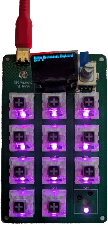
Many boards have been built with this system, from a mechanical keyboard macropad, to battery-powered IoT devices, to a USB source-measure unit.
Check out the examples page!
Example: from HDL to Keyboard
Overall flow: write HDL -> generate netlist -> import into KiCad PCB editor -> place and route (optionally iterating with HDL) -> export BoM and Gerbers -> optionally generate JLC PCBA data
A simplified version of the getting started tutorial is this snippet for a 3x4 mechanical keyboard:
provides a library of subcircuit generators, like switch matrices and USB-C ports, that automatically include supporting components like decoupling capacitors and pullup resistors
automatically selects generic parts like resistors and diodes against builtin parts tables
performs basic electrical checks on the design, including voltage and current limits, automating some common datasheet parameter checking
runs fully locally
This generates:
a netlist that can be imported into the KiCad PCB editor
... including hierarchical data, allowing subcircuit replication / channelization
... and have stable tstamps, allowing incremental updates to in-progress board layouts
a JLCPCB-compatible BoM
including a postprocessing script to shift part rotations from KiCad-generated component placements for JLC PCBA
multi-board support including connector-pair management
cross-hierarchy packing of multi-pack devices like dual op-amps and quad resistors
standard abstract component interfaces, allowing for custom implementations of parts like resistors (including from a parts table), and microcontrollers
full support for user component definition; very little is hard-coded into the infrastructure
Getting Started
text
pip install edg
On first run, the system will automatically download a compatible Java runtime for the core compiler.
Then, work through building a mechanical keyboard (including subcircuit layout replication) in the getting started tutorial.
The main goal of this HDL is to enable the creation of general subcircuit libraries that can be reused across many applications.
While graphical schematic tools support hierarchical sheets, direct re-use is limited because the sheets encode a lot of per-design information, like a specific resistor values or footprints.
Different users may have different requirements (e.g., different resistor values for a LED based on its input voltage, or preference for through-hole vs. surface-mount components).
This HDL addresses those limitations with two mechanisms:
Generators allow the implementation of the subcircuit to depend on high-level parameters.
A LED circuit could automatically size its resistor based on the input voltage.
Abstract parts allow the subcircuit to use generic parts with generic interfaces, which many parts can implement.
An abstract resistor interface could be implemented by through-hole and surface-mount resistors, enabling a generic LED circuit and deferring the choice.
The top-level designer can then specify refinements to make the specific choice of parts.
Both of these combined also present a higher level of abstraction for the board designer, more at the system architecture level-of-design than schematics.
We suspect this will also make it easier for novices to design boards, reducing the knowledge barrier to entry.
Graphical Tooling
The fundamental design structure is the hierarchical block diagram, and we expect graphical tooling can layer cleanly on top of the HDL core.
Our current focus is on the HDL core and parts libraries, but we are open to collaborations with those interested in building graphical tooling.
We suspect this may be particularly useful for novice users.
We built a proof-of-concept mixed textual / graphical IDE plugin for IntelliJ / PyCharm.
It has some nifty concepts (including a block diagram visualizer and design space sweep) but is rough around the edges and only sees basic maintenance.
It could be a good source for ideas for community developers.
Additional Notes
Project Status
This is functional has been used to produce a wide variety of boards over the years.
While the core is reasonably stable, as a pre-v1.0-release there are no formal guarantees of API stability.
In practice, deprecation shims are / will be maintained for common features if APIs change.
This started as an academic research project and continues to be developed as a personal project post-graduation, including for designing boards for fun.
(Some) Dragons Be Ahead
Many functional boards have been built with this system and most of the library parts have been physically tested (some across many designs), but there may still be bugs and edge cases.
You are recommended to sanity check generated designs during layout.
Be prepared for things to be rough around the edges.
The error messages in particular are not great and need work.
Building boards with the included libraries should be relatively straightforward, but building custom library parts is a more complex process.
Scope
The current libraries best support intermediate-level (and simpler) PCB designs.
This includes circuits with discrete microcontrollers, microcontroller modules (like ESP32s), and socketed dev boards.
Libraries include common subcircuits like switch matrices, digitally attached peripherals like I2C sensors, voltage converters, and some analog signal conditioning circuits.
Check out the subcircuits library folder and parts library folder.
There is no prescribed architecture and microcontrollers are not required.
ESPHome boards are a great fit.
Designs that do not decompose neatly(ish) into subcircuits blocks are a poor fit.
There is no support for high-speed digital design (like DDR memories).
There are some experimental RF subcircuits.
The electrical checks are not a design assurance tool and only automate some of the most common datasheet checks.
More advanced parameters, especially performance characteristics not related to maximum ratings, are currently out of scope of the electronics model.
Parameter Engine
This system has a concept of parameters (variables, think voltages and currents) that can be attached to blocks and propagate through ports.
This is limited to directed assignments, with the goal of deterministic, predictable compilation.
Assertions are supported on parameters to enforce electrical correctness checks.
Solving may happen within a single block with arbitrary Python code (for example, find the best set of E12 resistor values to implement a divider), but not across multiple blocks.
Search involving multiple blocks must be handled by the block exposing tuning knobs and the user turning those knobs with recompilation.
Parts Data
Most passive parts / discretes are selected from a 2022 JLCPCB parts table (included in this repository).
JLC no longer makes parts tables publicly available.
This parts table still works well and boards have been built using this table as recently as 2026.
Some basic parts have drifted and some parts may be no longer stocked.
Contributing
We take pull requests and would love to see contributions and collaborations!
What is EDG?:
Embedded Device Generation (or more generally Electronic Device Generation) was a prior version of this project that focused on algorithms and models for embedded device synthesis, though it lacked a user-facing component.
This project is a continuation of that work focusing on an end-to-end system, and for most of its development cycle has been called edg.
But, for the purposes of writing research papers, naming collisions are confusing and bad, and we chose to keep the repo and paper name consistent.
Parts
24
Qty
Value
Footprint
References
7
Resistor_SMD:R_0603_1608Metric
R1, R2, R3, R4, R5, R6, R7
3
edg:JlcToolingHole_1.152mm
H1, H2, H3
2
Capacitor_SMD:C_0805_2012Metric
C1, C2
1
LED_SMD:LED_0603_1608Metric
D1
1
20V 3.1A 860mW 112m?@4.5V,2.8A 1V@250?A P Channel SOT-23(SOT-23-3) MOSFETs ROHS
Package_TO_SOT_SMD:SOT-23
Q3
1
2?A@1V 85? Single 3.1V~3.5V 500mW 3.3V LL-34 Zener Diodes ROHS
Diode_SMD:D_MiniMELF
D2
1
30V 4A 44m?@10V,4.3A 1.4W 1.3V@250?A P Channel SOT-23-3L MOSFETs ROHS
Package_TO_SOT_SMD:SOT-23
Q1
1
60V 5.2A 50m?@10V,3.2A 27W 2.5V@250?A P Channel SOT-23-3 MOSFETs ROHS
It measures 30 × 18 mm and has 2 copper layers, 1.6 mm thick.
What parts does the ProtectedCharger use?
24 parts, built around the MCP73831T-2ACI/OT-HXY, S2B-PH-K-S-GW and S3B-PH-K-S. The full list of its parts is on this page, with links to each part's symbol and footprint where PCBKit's library has them.
Where can I download the ProtectedCharger KiCad files?
From the BerkeleyHCI/PolymorphicBlocks repository on GitHub, at the commit this page was made from: the board is examples/ProtectedCharger/ProtectedCharger.kicad_pcb. PCBKit opens the board in the browser, with nothing to install.
Can I use the ProtectedCharger design in my own project?
Its repository publishes it under the BSD-3-Clause licence: you may reuse it on that licence's terms (keep the author's notice, and for a copyleft licence share your changes alike).
A Python-based hardware description language for PCBs for higher-level (block-diagram / system-architecture level) PCB design through libraries of directly reusable subcircuit generators.
A Python-based hardware description language for PCBs for higher-level (block-diagram / system-architecture level) PCB design through libraries of directly reusable subcircuit generators.
A Python-based hardware description language for PCBs for higher-level (block-diagram / system-architecture level) PCB design through libraries of directly reusable subcircuit generators.
A Python-based hardware description language for PCBs for higher-level (block-diagram / system-architecture level) PCB design through libraries of directly reusable subcircuit generators.
A Python-based hardware description language for PCBs for higher-level (block-diagram / system-architecture level) PCB design through libraries of directly reusable subcircuit generators.
A Python-based hardware description language for PCBs for higher-level (block-diagram / system-architecture level) PCB design through libraries of directly reusable subcircuit generators.
A Python-based hardware description language for PCBs for higher-level (block-diagram / system-architecture level) PCB design through libraries of directly reusable subcircuit generators.
A Python-based hardware description language for PCBs for higher-level (block-diagram / system-architecture level) PCB design through libraries of directly reusable subcircuit generators.
A Python-based hardware description language for PCBs for higher-level (block-diagram / system-architecture level) PCB design through libraries of directly reusable subcircuit generators.
A Python-based hardware description language for PCBs for higher-level (block-diagram / system-architecture level) PCB design through libraries of directly reusable subcircuit generators.
A Python-based hardware description language for PCBs for higher-level (block-diagram / system-architecture level) PCB design through libraries of directly reusable subcircuit generators.
A Python-based hardware description language for PCBs for higher-level (block-diagram / system-architecture level) PCB design through libraries of directly reusable subcircuit generators.
Jarvis HomeDeck: a Raspberry Pi CM4 carrier board and voice-assistant software for a 7-inch smart display (KiCad hardware, generated from Python, plus the Python/JS assistant)
The consumer half of the ephemerkey system, and the second PCB in this repo (alongside hardware/ephemerkey/, sharing the same scripts/kschgen.py engine, Makefile, and lib tables — the multi-project layout used by…
This directory contains the editable KiCad 10 source for the 70 mm × 52 mm, four-layer Pager-1 main carrier. The display, keypad, protected Li-Po pack, and analog accelerator are external assemblies.