2 layers
IgnisV1-TP4056
TehoorMarjan/Ignis
An autonomous flame-shaped lamp/nightlight controlled by microcontroller with WS2812B LED ring and integrated Qi wireless charging. 🔥
11 parts1
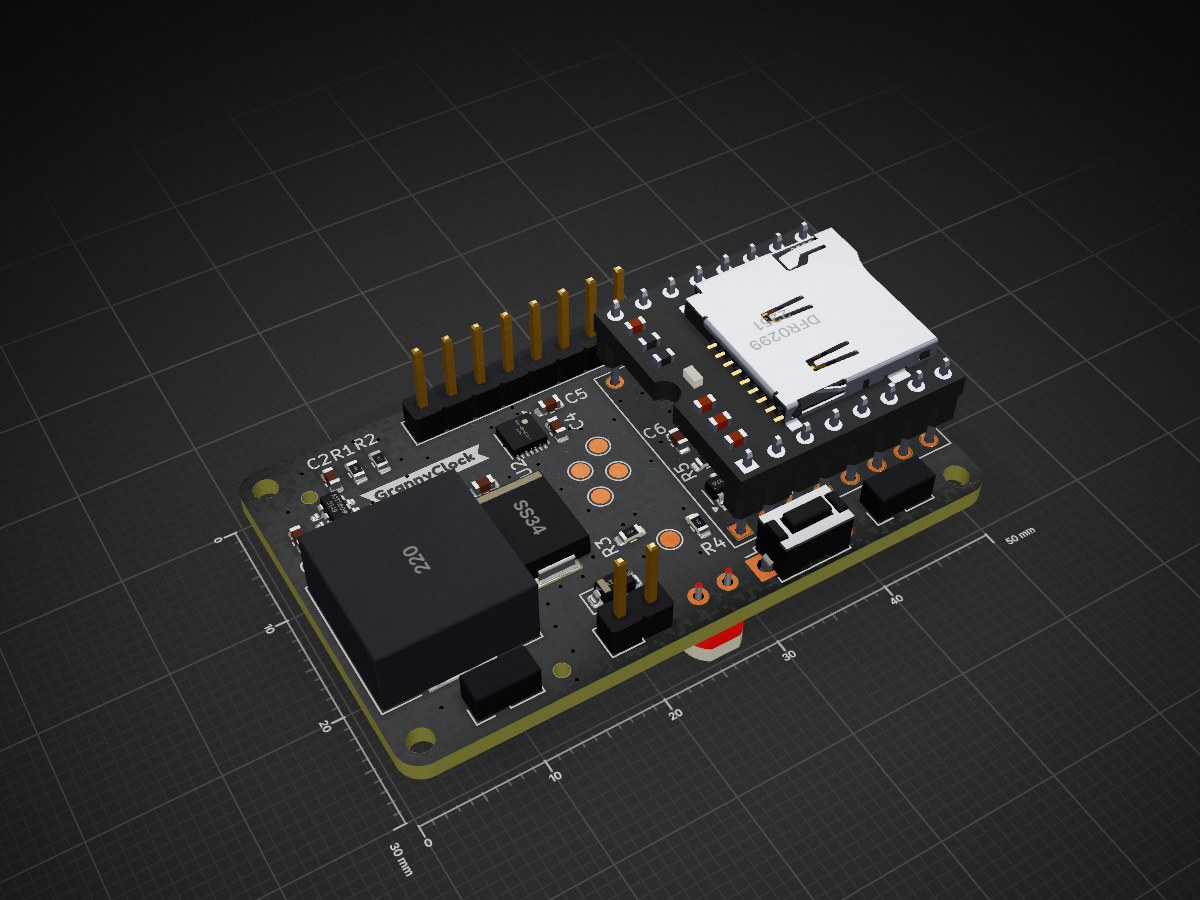
 TehoorMarjan/grannyclock
The GrannyClock PCB is an add-on module designed for the TFA Dostmann 60.3518.01 radio-controlled clock mechanism.
ClockV1 is an open-source printed circuit board by TehoorMarjan, from the TehoorMarjan/grannyclock repository on GitHub. It is a 2-layer board of 50 × 30 mm with 55 parts on 51 nets, routed with 323 tracks and 75 vias.
It is built around the ATTINY1616-MN, DFR0299 and MT3608, with the MAX14611ETD+T, AO3407A and FDN327N among its other parts. Its parts include 12 resistors, 8 capacitors, 4 ICs, 4 diodes and 4 connectors. It belongs with the AVR (ATmega, ATtiny) boards of this library.


The GrannyClock PCB is an add-on module designed for the TFA Dostmann 60.3518.01 radio-controlled clock mechanism. It provides enhanced audio capabilities to create a talking/chiming clock while preserving battery life and the original clock functionality.
This PCB interfaces with the TFA clock module signal pins (MU, BR, BA, RF) to detect the current time and play appropriate audio files from an SD card through an integrated DFPlayer Mini MP3 module.
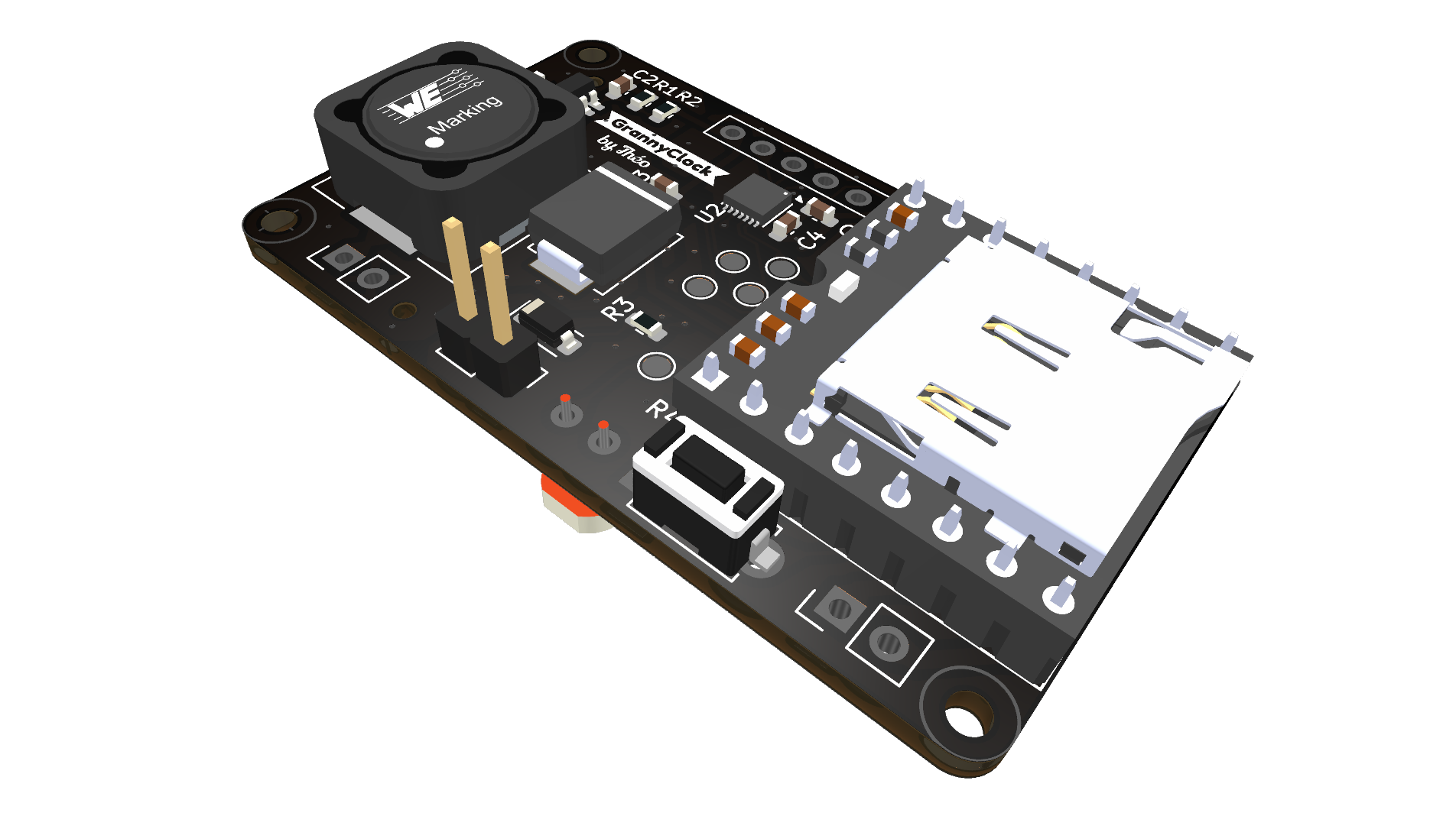
Power Efficient Design:
Intelligent Operation:
Debugging:
This repository contains all necessary KiCad files for the GrannyClock PCB:
ClockV1.kicad_sch - Schematic capture fileClockV1.kicad_pcb - PCB layout fileClockV1.kicad_pro - KiCad project fileoutput/ - Generated output files (3D renders, PDFs)production/ - Manufacturing files (gerbers, BOM, position files)The TFA clock module operates at 1.5V logic levels (single AA power cell), while the microcontroller uses 3.3V. A MAX14611ETD+ level translator chip provides reliable communication between these voltage domains. This component was chosen after testing revealed that traditional MOSFET-based level shifters were unreliable at 1.5V.
The DFPlayer Mini module was selected for audio playback capabilities due to:
Power to this module is completely cut when not in use to maximize battery life, as it only needs to be active approximately 16 times per day for brief periods.
An onboard photoresistor allows the clock to detect ambient light levels and mute audio output during nighttime or in dark rooms, preventing disturbances during sleep.
The PCB is designed for manufacture through JLCPCB with SMT assembly. Key production files are located in the production/ directory:
bom.csv - Bill of Materialspositions.csv - Component placement dataGrannyClock_1.0.zip - Complete manufacturing packageNotes on component sourcing:
The ATtiny1616 is programmed via the UPDI interface. Compatible programmers include:
This PCB interfaces with the TFA Dostmann 60.3518.01 clock module via a dedicated connector (J3), which connects to the following signal lines:
The GrannyClock is part of a larger project that includes:
This hardware design is licensed under the CERN Open Hardware License v2 - Permissive (CERN-OHL-P).
| Qty | Value | Footprint | References |
|---|---|---|---|
| 4 | 100nF | Capacitor_SMD:C_0603_1608Metric | C5, C6, C7, C8 |
| 4 | MountingHole | MountingHole:MountingHole_2mm | H1, H2, H5, H7 |
| 3 | Conn_01x02 | Connector_PinHeader_2.54mm:PinHeader_1x02_P2.54mm_Vertical | J1, J2, J4 |
| 3 | ToolingHole | MountingHole:ToolingHole_1.152mm | H3, H4, H6 |
| 2 | 100 | Resistor_SMD:R_0603_1608Metric | R7, R11 |
| 2 | 10k | Resistor_SMD:R_0603_1608Metric | R4, R10 |
| 2 | 22uF | Capacitor_SMD:C_0603_1608Metric | C1, C3 |
| 2 | 330 | Resistor_SMD:R_0603_1608Metric | R6, R8 |
| 1 | 1.5M | Resistor_SMD:R_0603_1608Metric | R2 |
| 1 | 100k | Resistor_SMD:R_0603_1608Metric | R9 |
| 1 | 10nF | Capacitor_SMD:C_0603_1608Metric | C2 |
| 1 | 1uF | Capacitor_SMD:C_0603_1608Metric | C4 |
| 1 | 22uH | Inductor_SMD:L_12x12mm_H4.5mm | L1 |
| 1 | 330k | Resistor_SMD:R_0603_1608Metric | R1 |
| 1 | 4.7k | Resistor_SMD:R_0603_1608Metric | R5 |
| 1 | 470 | Resistor_SMD:R_0603_1608Metric | R3 |
| 1 | AO3407A | Package_TO_SOT_SMD:SOT-23-3 | Q1 |
| 1 | ATtiny1616-M | Package_DFN_QFN:VQFN-20-1EP_3x3mm_P0.4mm_EP1.7x1.7mm_ThermalVias | U3 |
| 1 | Conn_01x08 | Connector_PinHeader_2.54mm:PinHeader_1x08_P2.54mm_Vertical | J3 |
| 1 | DFR0299 | Snapeda:DFR0299_MODULE_DFR0299 | U4 |
| 1 | DFR_EN | TestPoint:TestPoint_Pad_D1.5mm | TP7 |
| 1 | FDN327N | Snapeda:FDN327N_SSOT-3 | Q2 |
| 1 | G*** | kibuzzard-681FCEAB | kibuzzard-2 |
| 1 | G*** | kibuzzard-681FCE61 | kibuzzard-3 |
| 1 | G*** | kibuzzard-681BEBFE | kibuzzard-1 |
| 1 | Green | LED_SMD:LED_0603_1608Metric | D3 |
| 1 | HBA | TestPoint:TestPoint_Pad_D1.5mm | TP1 |
| 1 | HMU | TestPoint:TestPoint_Pad_D1.5mm | TP2 |
| 1 | HPONBR | TestPoint:TestPoint_Pad_D1.5mm | TP5 |
| 1 | HRF | TestPoint:TestPoint_Pad_D1.5mm | TP4 |
| 1 | LBAT46T1G | Diode_SMD:D_SOD-123 | D2 |
| 1 | LDR_MES | TestPoint:TestPoint_Pad_D1.5mm | TP3 |
| 1 | MAX14611ETD+T | Package_DFN_QFN:TDFN-14-1EP_3x3mm_P0.4mm_EP1.78x2.35mm | U2 |
| 1 | MT3608 | Package_TO_SOT_SMD:SOT-23-6 | U1 |
| 1 | PON/BR Select | Jumper:SolderJumper-3_P1.3mm_Open_RoundedPad1.0x1.5mm | JP2 |
| 1 | R_Photo | OptoDevice:R_LDR_4.9x4.2mm_P2.54mm_Vertical | R12 |
| 1 | Red | LED_SMD:LED_0603_1608Metric | D4 |
| 1 | SS34 | Snapeda:SS34_DIO_SS34 | D1 |
| 1 | SW_Push | Button_Switch_THT:SW_PUSH_1P1T_6x3.5mm_H4.3_APEM_MJTP1243 | SW1 |
| 1 | ~{SND_BUSY} | TestPoint:TestPoint_Pad_D1.5mm | TP6 |
| 1 | ~{TS} Select | Jumper:SolderJumper-3_P1.3mm_Open_RoundedPad1.0x1.5mm | JP1 |
It measures 50 × 30 mm and has 2 copper layers, 1.69 mm thick.
55 parts, built around the ATTINY1616-MN, DFR0299, MT3608 and MAX14611ETD+T. The full list of its parts is on this page, with links to each part's symbol and footprint where PCBKit's library has them.
From the TehoorMarjan/grannyclock repository on GitHub, at the commit this page was made from: the board is PCB/ClockV1/ClockV1.kicad_pcb and its schematic PCB/ClockV1/ClockV1.kicad_sch. PCBKit opens the board in the browser, with nothing to install.
Its repository states no licence, so its author keeps all rights: ask TehoorMarjan before reusing the design.
TehoorMarjan/Ignis
An autonomous flame-shaped lamp/nightlight controlled by microcontroller with WS2812B LED ring and integrated Qi wireless charging. 🔥


nexyugainnovations-collab/Tacktile_book_STM-Version
STM32-based PCB design and audio files for the Tacktile interactive tactile book (v1.0)

hackclub/reflow
A YSWS for the northern hemisphere's summer and the aussie's winter. Run by @pmnlla, with love and loads of carrots.

ephemerkey/ephemerkey
The consumer half of the ephemerkey system, and the second PCB in this repo (alongside hardware/ephemerkey/, sharing the same scripts/kschgen.py engine, Makefile, and lib tables — the multi-project layout used by…

cybloxyz/tap-tap-trulala
RFID music player, modification or improvitation from juukebox by ananords (instructables)
