2 layers100 × 130 mm
Fan controller pcb
LennardBoediger/dmx-fan-controller
DMX controller for two ancient industrial fans
53 partsGPL-3.0

 en4rab/Paxtogeddon-OLED-PCB5
Hardware files for the Paxtogeddon reader with OLED display
Paxtogeddon pcb is an open-source printed circuit board by en4rab, from the en4rab/Paxtogeddon-OLED-PCB repository on GitHub, published under the MIT licence. It is a 2-layer board of 42 × 60.2 mm with 27 parts on 35 nets, routed with 8 tracks and 20 vias.
It is built around the MC7805CDTG and MMBT3904. Its parts include 8 resistors, 6 transistors, 3 ICs, 2 capacitors and 2 connectors. It belongs with the lEDs and displays boards and the ESP32 and RISC-V boards of this library.


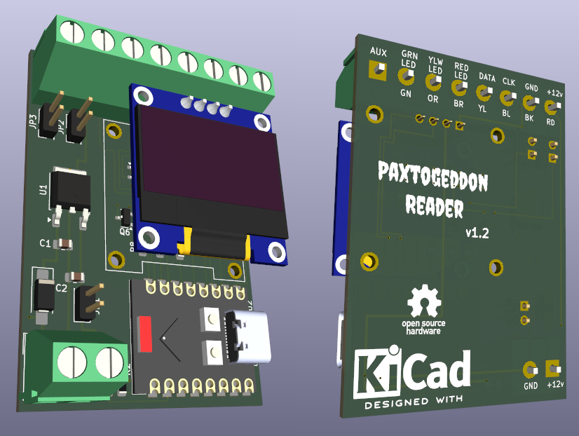
The kicad directory contains the kicad project files to make a PCB for the Paxtogeddon reader. This was a project to learn Kicad and PCB design so set your expectations accordingly! If you just want to make one Paxtogeddon reader to use then you might find using 00Waz's protoboard design quicker and easier than ordering pcb's and smt parts from China.
The gerbers directory contains the gerbers for the v1.2 board and a zip file paxtogeddon-gerbers_v1_2.zip which is the zip file uploaded to JLC for manufacture of the PCB's.
The case directory contains the STL files and parts list for the 3D printed case to suit an Anker 525, 325 or 313 power bank.
This uses mostly the same code written by Daniel as the board by 00Waz with some additions to write to an OLED display. However the pin assignments are different and the pins to playback a card are now the same as those used to sniff so the associated headers and transistors can be left off. If this ever gets another revision of the pcb they will be removed. The PaxtogeddonReaderV1 directory contains the first attempt at adding an OLED, the additions were done by en4rab so any mistakes and poor code are my fault and not Daniels!
PaxtogeddonReaderV2.2 contains Daniel's improved version 2.2 code which supports both this PCB version and the protoboard design by Waz. It uses custom cards to configure the reader. Information on how to rewrite Paxton cards to use as the config cards can be found in MAKE-CARDS.md
This firmware now supports a second esp module connected to the paxtogeddon aux pin to trigger a cheap fitness band to vibrate when a card is read and new with v2.2 support for the paxton hand free interface and hands free fobs.
Assembly is fairly straightforward. When soldering the 4 pin female header for the OLED it is easier to align it if you attach the brass standoffs to an OLED, put the header on the OLED pins then use it as a jig to hold the header in position while you solder it.
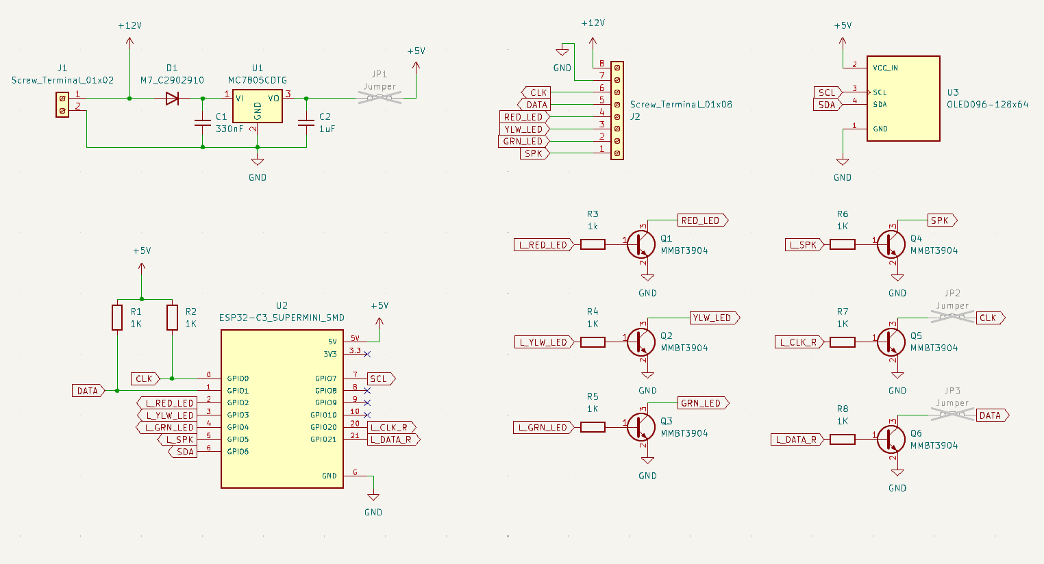
The jumper JP1 was for development to allow the 5v to be separated from the ESP32 so the Paxton reader could be powered by 12v while the esp was powered by usb for debugging. In normal use it should be connected.
JP2 and JP3 were to disconnect the card playback pins if that was not needed. In the latest firmware are unused and should be left disconnected.
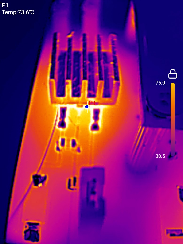
Once the PCB has been soldered and cleaned use the Halnziye HY910 thermal glue to stick a small aluminium heatsink to the 7805 regulator. Initial tests without a heatsink had the regulator at about 89C adding a small heatsink lowered this to about 75C its a bit of a bodge but it seems to be working ok.
This is a list of the parts used. They are not necessarily the best source and if you are being organised you could probably source everything in one order from Mouser/RS/Farnell but the links given are what was used. the 8 way screw terminal was 2x4 way terminals as they were easier to source.
[!CAUTION] The ESP32 supermini module has a near identical clone that is badly made and has problems with the wifi, this site describes the issue and how to spot the bad boards https://roryhay.es/blog/esp32-c3-super-mini-flaw TL;DR avoid the boards with "mouse bites" to separate the boards. If you do get a bad board and wifi doesn't work one test board worked better with a small blob of blu-tak stuck on the antenna simulating a finger touching the antenna. Guess how I figured that one out 🤣
[!WARNING]
0.96" OLED modules come in at least 4 different variants the most significant difference being the order of the pins. This board uses a 4 pin module with GND on the left most pin. They also differ in size and hole spacing. look for a seller showing a board with GME12864-11-12-13 on the back as shown.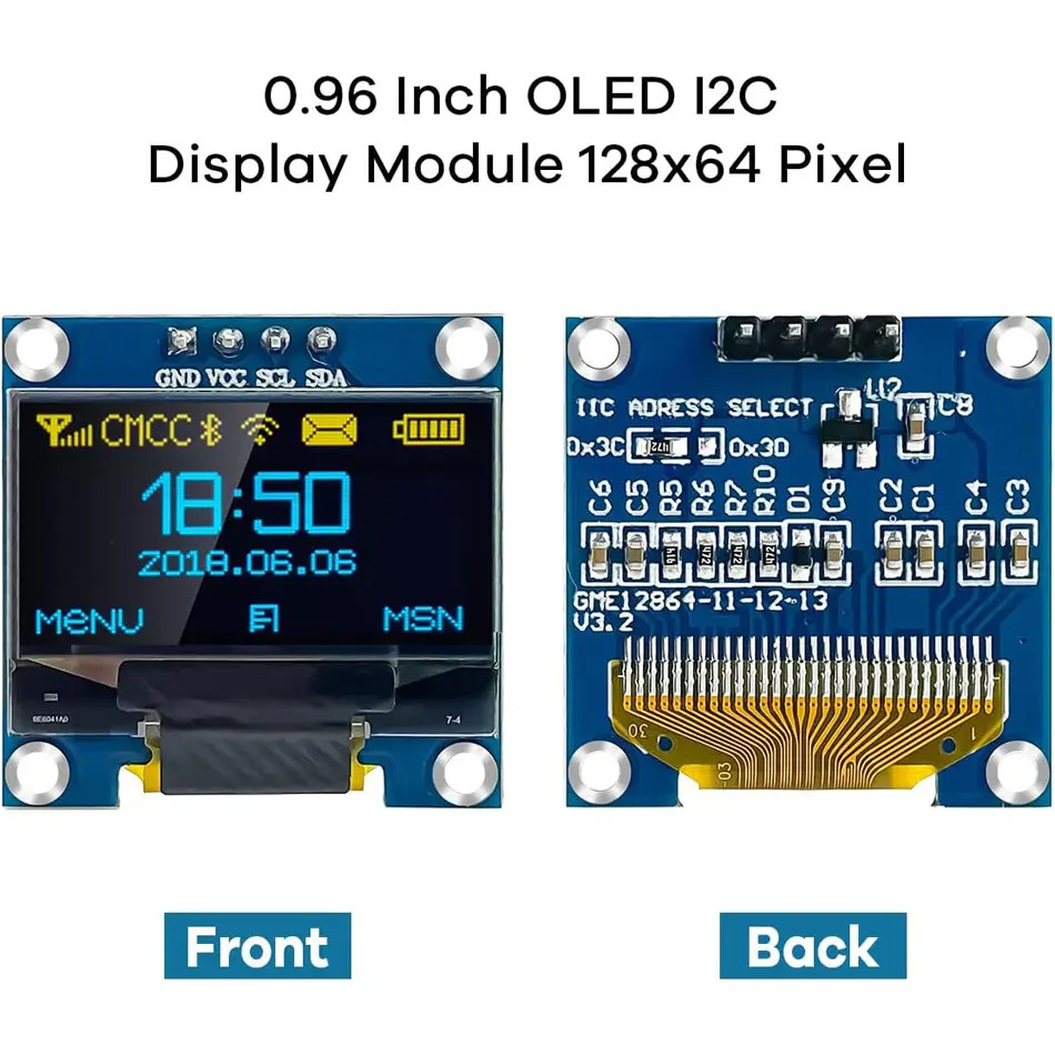
The latest version of the firmware being developed handles playback differently and doesn't use separate pins. This board used GPIO 20 and 21 for playback and jumpers JP2 and JP3 were to physically disconnect the lines if you didn't want to be able to playback cards. As playback is now done with the same pins as reading they are not used and can be left disconnected.
| Qty | Value | Footprint | References |
|---|---|---|---|
| 7 | 1K | Resistor_SMD:R_0805_2012Metric | R1, R2, R4, R5, R6, R7, R8 |
| 6 | MMBT3904 | Package_TO_SOT_SMD:SOT-23 | Q1, Q2, Q3, Q4, Q5, Q6 |
| 3 | Jumper | Connector_PinHeader_2.54mm:PinHeader_2x01_P2.54mm_Vertical | JP1, JP2, JP3 |
| 1 | 1k | Resistor_SMD:R_0805_2012Metric | R3 |
| 1 | 1uF | Capacitor_SMD:C_0805_2012Metric_Pad1.18x1.45mm_HandSolder | C2 |
| 1 | 330nF | Capacitor_SMD:C_0805_2012Metric_Pad1.18x1.45mm_HandSolder | C1 |
| 1 | ESP32-C3_SUPERMINI_SMD | paxtogeddon:MODULE_ESP32-C3_SUPERMINI | U2 |
| 1 | M7_C2902910 | Diode_SMD:D_SMA_Handsoldering | D1 |
| 1 | MC7805CDTG | Package_TO_SOT_SMD:TO-252-2 | U1 |
| 1 | OLED096-128x64 | paxtogeddon:MODULE_ER-OLED096-I2C | U3 |
| 1 | Screw_Terminal_01x02 | TerminalBlock_Altech:Altech_AK100_1x02_P5.00mm | J1 |
| 1 | Screw_Terminal_01x08 | TerminalBlock_Altech:Altech_AK100_1x08_P5.00mm | J2 |
The 25 most common of 27 parts.
LennardBoediger/dmx-fan-controller
DMX controller for two ancient industrial fans


TalismanDesign/PocketMage_PDA
An E-Ink PDA device using the ESP32 S3.

fossasia/pslab-hardware
PSLab Hardware Design and Schematics https://pslab.io


iMike78/nest-mini-drop-in-pcb
Drop-in PCB replacement for the Google Nest Mini v2 with ESP32-S3, ESP32-P4 and optional ESP32-C6. Inspired by Onju Voice and Home Assistant Voice PE.

ohmtech-rdi/eurorack-blocks
Software to Hardware Prototyping for Eurorack using C++, Max/Gen~ or Faust
It measures 42 × 60.2 mm and has 2 copper layers, 1.6 mm thick.
27 parts, built around the MC7805CDTG and MMBT3904. The full list of its parts is on this page, with links to each part's symbol and footprint where PCBKit's library has them.
From the en4rab/Paxtogeddon-OLED-PCB repository on GitHub, at the commit this page was made from: the board is kicad/paxtogeddon-pcb.kicad_pcb and its schematic kicad/paxtogeddon-pcb.kicad_sch. PCBKit opens the board in the browser, with nothing to install.
Its repository publishes it under the MIT licence: you may reuse it on that licence's terms (keep the author's notice, and for a copyleft licence share your changes alike).