4 layers53.1 × 98 mm
 electro-practically/wled-controller
WLED ESP32 controller powered by USB-C Power Delivery.
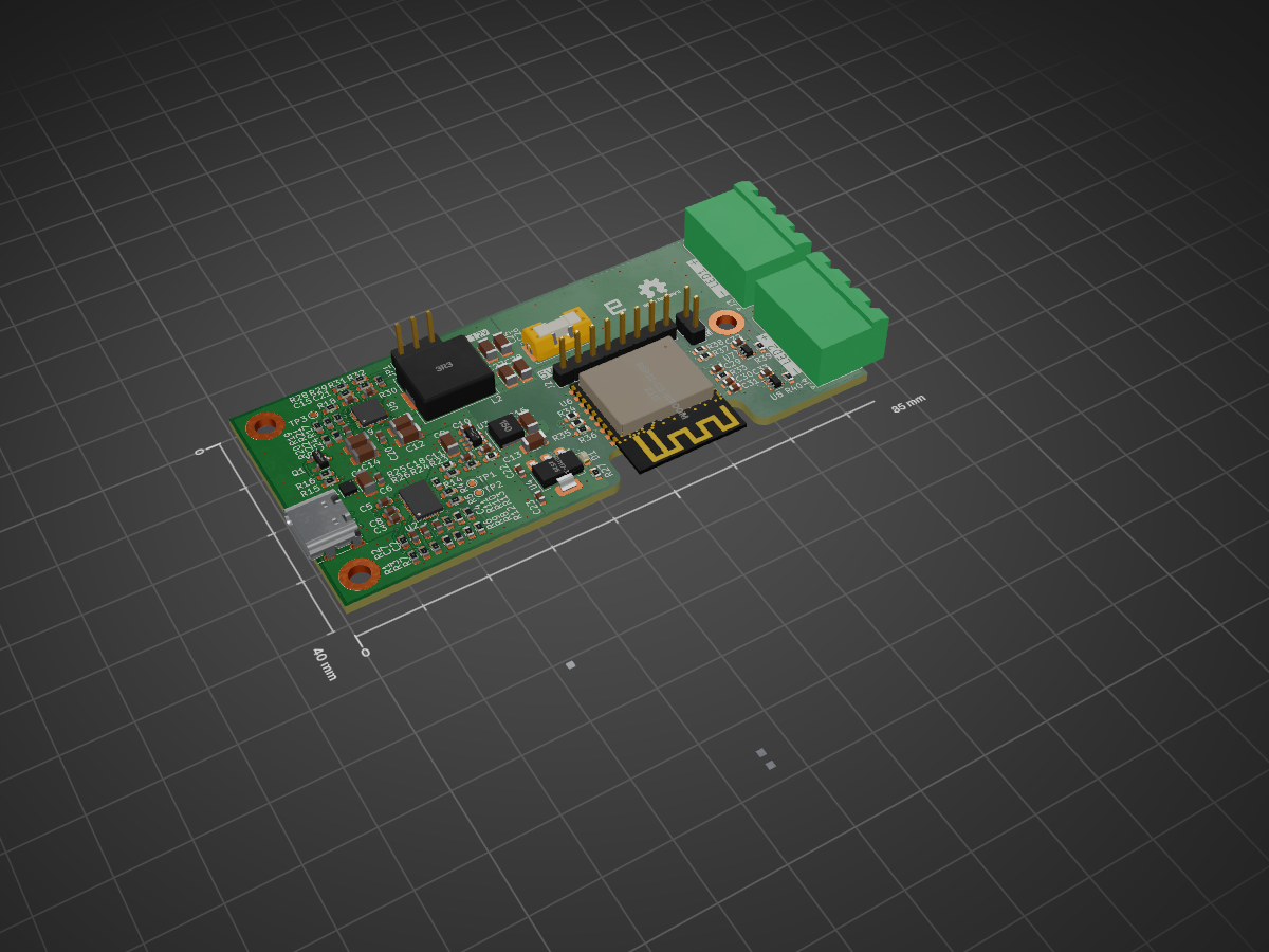
Wled controller is an open-source printed circuit board by electro-practically, from the electro-practically/wled-controller repository on GitHub, published under the CERN-OHL-P-2.0 licence. It is a 4-layer board of 85 × 40 mm with 99 parts on 72 nets, routed with 426 tracks and 176 vias.
It is built around the 74AHCT1G125SE, ESP32-C3-WROOM-02-H4 and SIC437BED, with the TPS54202DDC, AMS1117-3.3 and TVS2200DRV among its other parts. Its parts include 40 resistors, 33 capacitors, 8 ICs, 4 connectors and 2 inductors. It belongs with the power boards and the ESP32 and RISC-V boards of this library.


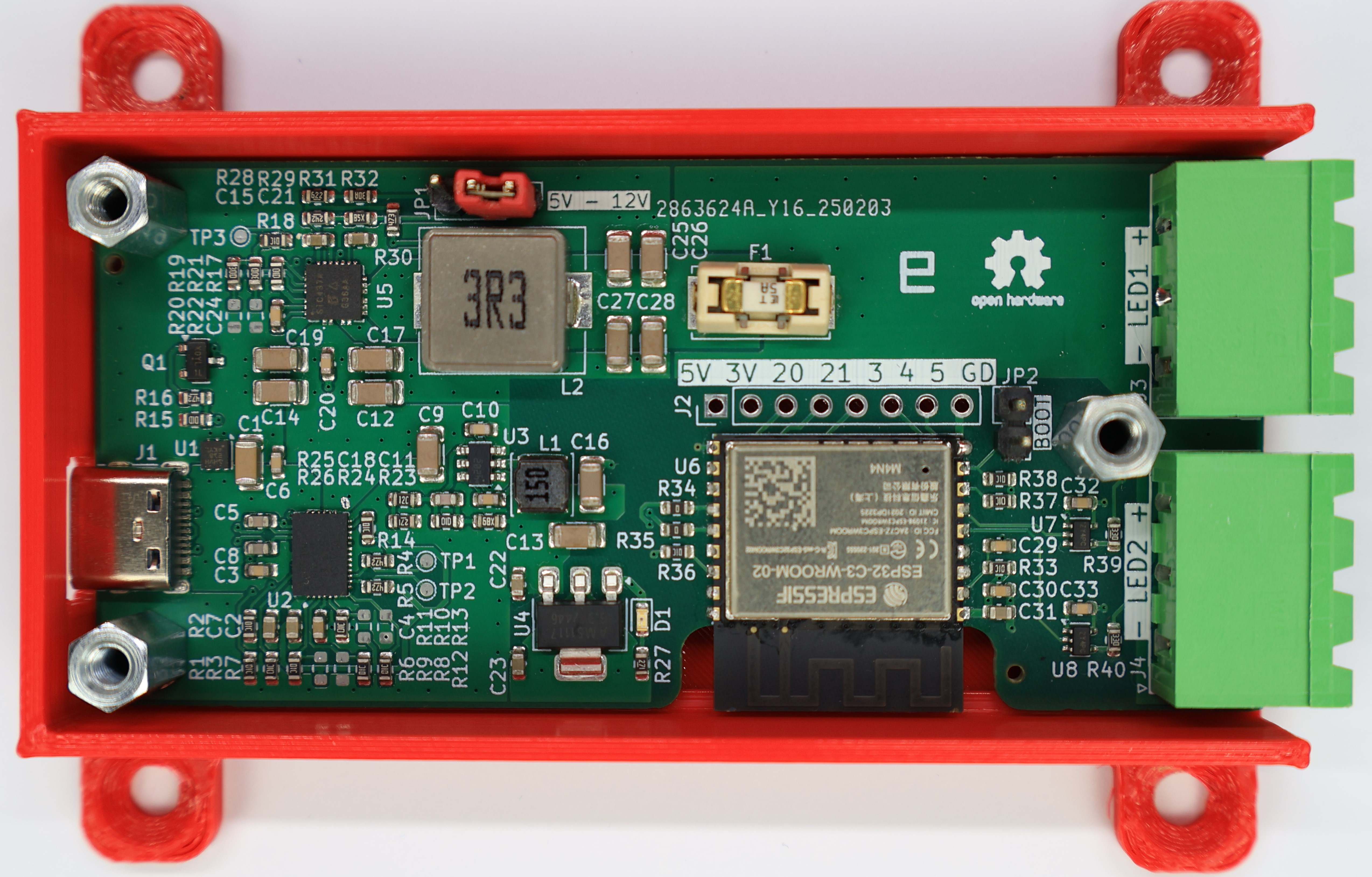
WLED Controller is a compact, single-sided PCB designed to run WLED firmware and control two addressable LED strips. It is powered entirely via USB-C Power-Delivery and supports either 5V or 12V LED strips, with a maximum power of 60W. Compatible with popular LED types such as WS2812B (5V) and WS2815 (12V). It offers a clean, efficient solution for custom lighting projects.
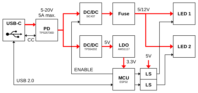
The entire board is powered via the USB-C connector. Voltage and current levels are negotiated through the TPS25730D USB Power Delivery (PD) controller, based on onboard configuration resistors. The supported input range is 5–20 V and 0.5–5 A, and the controller always negotiates the highest available voltage profile supported by the connected power adapter. These voltage/current profiles can be customized by soldering different resistor values.
There are two power paths:
LED Power Path: supplies power to the LED strips. The input voltage is stepped down by a SiC437 buck converter, providing high-efficiency regulation tailored to the selected LED voltage (5 V or 12 V). This path is protected by a fuse.
Logic Power Path: supplies power to the ESP32 and other low-power components. This path uses a TPS54202 buck converter to generate a stable 5 V rail, which is further regulated down to 3.3 V using an AMS1117 low-dropout (LDO) regulator.
A dedicated ENABLE signal from the ESP32 is used to control the LED power converter (SiC437). When LEDs are turned off in WLED, this signal disables the converter entirely - removing the need for additional output relays or transistors typically used to disconnect LED power.
The USB-C connector also provides a direct connection to the ESP32 via the USB 2.0, allowing firmware flashing and debug access without additional interfaces.
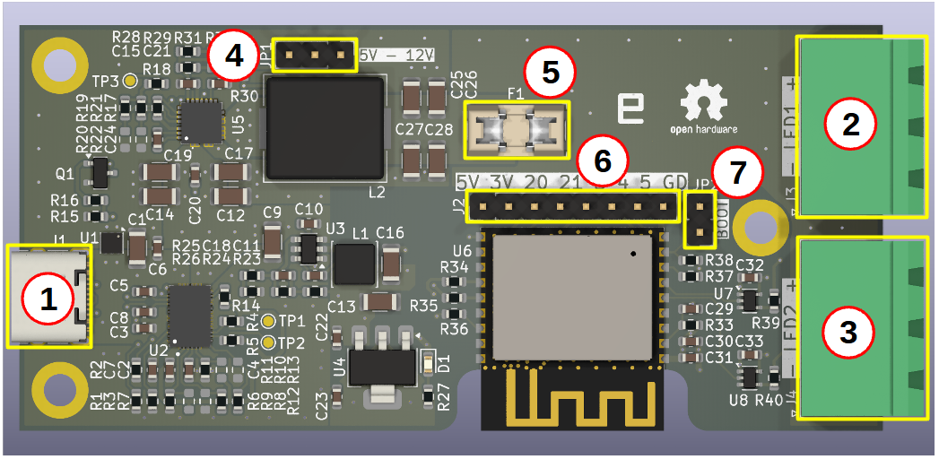
Follow these steps to flash the WLED firmware and configure the board:
If you power a long LED strip with relatively high power consumption, it may be necessary to provide heat dissipation for the controller - for example, using an aluminum case or a case with a fan. Most of the heat is dissipated by the SiC437 buck converter.
The controller was tested with a standard USB power brick used for phone charging with USB Power Delivery capability. However, it should also work with other USB-C devices that support Power Delivery in source mode - for example, power banks, monitors, laptops, and similar devices. If you plan to power the controller from such a source, ensure that it supports the required USB PD power profile.
| Qty | Value | Footprint | References |
|---|---|---|---|
| 13 | 10k | Resistor_SMD:R_0603_1608Metric | R1, R2, R3, R7, R8, R11, R12, R14, R18, R33, R36, R37, R38 |
| 10 | 100n | Capacitor_SMD:C_0603_1608Metric | C3, C6, C10, C11, C20, C24, C29, C30, C32, C33 |
| 6 | 10u | Capacitor_SMD:C_0603_1608Metric | C2, C4, C7, C22, C23, C31 |
| 6 | 22u | Capacitor_SMD:C_1206_3216Metric | C13, C16, C25, C26, C27, C28 |
| 6 | DNP | Resistor_SMD:R_0603_1608Metric | R6, R9, R10, R13, R20, R22 |
| 5 | 10u | Capacitor_SMD:C_1206_3216Metric | C9, C12, C14, C17, C19 |
| 3 | 100k | Resistor_SMD:R_0603_1608Metric | R15, R17, R24 |
| 3 | 4k7 | Resistor_SMD:R_0603_1608Metric | R4, R5, R16 |
| 3 | MountingHole | MountingHole:MountingHole_3.2mm_M3_DIN965_Pad | H1, H2, H3 |
| 3 | TESTPOINT | TestPoint:TestPoint_Pad_D1.0mm | TP1, TP2, TP3 |
| 2 | 0R | Resistor_SMD:R_0603_1608Metric | R34, R35 |
| 2 | 1u | Capacitor_SMD:C_0603_1608Metric | C15, C21 |
| 2 | 200k | Resistor_SMD:R_0603_1608Metric | R19, R21 |
| 2 | 270R | Resistor_SMD:R_0603_1608Metric | R26, R27 |
| 2 | 330p | Capacitor_SMD:C_0603_1608Metric | C5, C8 |
| 2 | 33R | Resistor_SMD:R_0603_1608Metric | R39, R40 |
| 2 | 74AHCT1G125 | Package_TO_SOT_SMD:SOT-353_SC-70-5 | U7, U8 |
| 1 | 100p | Capacitor_SMD:C_0603_1608Metric | C18 |
| 1 | 13k | Resistor_SMD:R_0603_1608Metric | R25 |
| 1 | 15uH | Inductor_SMD:L_Changjiang_FNR4020S | L1 |
| 1 | 200R | Resistor_SMD:R_0603_1608Metric | R32 |
| 1 | 2k4 | Resistor_SMD:R_0603_1608Metric | R28 |
| 1 | 3u3 | Inductor_SMD:L_Chilisin_BMRF00101040 | L2 |
| 1 | 47k | Resistor_SMD:R_0603_1608Metric | R30 |
| 1 | 49R9 | Resistor_SMD:R_0603_1608Metric | R23 |
| 1 | 4u7 | Capacitor_SMD:C_1206_3216Metric | C1 |
| 1 | 6k2 | Resistor_SMD:R_0603_1608Metric | R31 |
| 1 | 75R | Resistor_SMD:R_0603_1608Metric | R29 |
| 1 | 8A | Fuse:Fuseholder_Littelfuse_Nano2_154x | F1 |
| 1 | AMS1117-3.3 | Package_TO_SOT_SMD:SOT-223-3_TabPin2 | U4 |
| 1 | AO3400A | Package_TO_SOT_SMD:SOT-23 | Q1 |
| 1 | BOOT | Connector_PinHeader_2.54mm:PinHeader_1x02_P2.54mm_Vertical | JP2 |
| 1 | ESP32-C3-WROOM-02 | PCM_Espressif:ESP32-C3-WROOM-02 | U6 |
| 1 | EXT | Connector_PinHeader_2.54mm:PinHeader_1x08_P2.54mm_Vertical | J2 |
| 1 | LED1 | Connector_Phoenix_MSTB:PhoenixContact_MSTBA_2,5_3-G-5,08_1x03_P5.08mm_Horizontal | J3 |
| 1 | LED2 | Connector_Phoenix_MSTB:PhoenixContact_MSTBA_2,5_3-G-5,08_1x03_P5.08mm_Horizontal | J4 |
| 1 | LED_VOLT_SEL | Connector_PinHeader_2.54mm:PinHeader_1x03_P2.54mm_Vertical | JP1 |
| 1 | SiC437 | wled-footprints:SIC437BEDT1GE3 | U5 |
| 1 | TPS25730D | wled-footprints:IC_TPS25750DRJKR | U2 |
| 1 | TPS54202DDC | Package_TO_SOT_SMD:SOT-23-6 | U3 |
| 1 | TVS2200DRV | Package_SON:WSON-6-1EP_2x2mm_P0.65mm_EP1x1.6mm | U1 |
| 1 | USB | Connector_USB:USB_C_Receptacle_XKB_U262-16XN-4BVC11 | J1 |
| 1 | YELLOW | LED_SMD:LED_0603_1608Metric | D1 |
The 98 most common of 99 parts.
It measures 85 × 40 mm and has 4 copper layers, 1.61 mm thick.
99 parts, built around the 74AHCT1G125SE, ESP32-C3-WROOM-02-H4, SIC437BED and TPS54202DDC. The full list of its parts is on this page, with links to each part's symbol and footprint where PCBKit's library has them.
From the electro-practically/wled-controller repository on GitHub, at the commit this page was made from: the board is pcb/wled-controller.kicad_pcb and its schematic pcb/esp32.kicad_sch. PCBKit opens the board in the browser, with nothing to install.
Its repository publishes it under the CERN-OHL-P-2.0 licence: you may reuse it on that licence's terms (keep the author's notice, and for a copyleft licence share your changes alike).


etiennechlt/electronic-chess
Générée par tools/boardgen (module power). 100 x 60 mm, 2 couches, plan de masse en face arrière. Elle gère trois cellules plates 1S 5 Ah.

jjsprandel/SCAN_PCB
Welcome to the SCAN repository! Below, you will find all the necessary information, from hardware design to software documentation.

fxp/cat-feeder
AI-agent-designed automatic cat feeder (ESP32-C3 + HX711 + motor): schematic, PCB (Gerber/BOM), firmware, enclosure, docs

thomaslr/plant-esp32
This directory contains the production files, Pick & Place centroid files (CPL), Bill of Materials (BOM), KiCad design source files, and 3D renders for the Monolithic Onboard SMD Edition of the Plant ESP32 watering…