2 layers83.8 × 51 mm
Mega wifi
jfryman/mw-cart
MegaWiFi Mega Drive/Genesis Wi-Fi cartridge — Rev.C fork (TI TL16C550D UART, 20 MHz / 1.25 Mbaud). Upstream: gitlab.com/doragasu/mw-cart
56 parts

 fxp/cat-feeder
AI-agent-designed automatic cat feeder (ESP32-C3 + HX711 + motor): schematic, PCB (Gerber/BOM), firmware, enclosure, docs
Cat feeder is an open-source printed circuit board by fxp, from the fxp/cat-feeder repository on GitHub. It is a 2-layer board of 66 × 60 mm with 35 parts on 18 nets, routed with 187 tracks and 32 vias.
It is built around the ESP32-C3-WROOM-02-H4, AMS1117-3.3 and 1N5819WS, with the AO3400A among its other parts. Its parts include 9 resistors, 6 capacitors, 4 connectors, 3 diodes and 3 switches. It belongs with the ESP32 and RISC-V boards of this library.


ESP32-C3 + HX711 称重 + 电机下料。外壳、电路板、固件、App 由不同的 Agent(Z.ai ZCode 多 Agent 团队)分工完成, 这里是整条链路的产物:原理图、两版 PCB(Gerber / BOM / 贴片坐标)、固件、外壳、方案文档和运行记录,按两个轮次整理。
状态:Rev A 和 Rev B,都只做到「设计 + 文件」这一步。 没有在真机上验证过:固件只通过了主机测试和编译(没有烧录真机),电路板的元件取值/极性没有对照数据手册查过 (只检查了引脚一致性和可制造性,DRC 0 错误 / 0 未连接)。 Rev A 的 Gerber 已备好给嘉立创(jlc.com);Rev B 的订单包是给人工审阅的,文件里写明「没有下单」。 本仓库不记录是否付款、是否生产。
| 第一轮 — Rev A | 第二轮 — Rev B | |
|---|---|---|
| 元件 / 网络 | 28 个 / 18 个 | 32 个 / 21 个 |
| 做了什么 | 第一块板;固件、外壳和多 Agent 运行报告 | 加电机电流检测(INA199A2 + 20 mΩ 开尔文分流电阻 + 测试点),J1、J4 挪到右边缘;订单包 |
| 板子 | 66×60 mm 双层,DRC 0 / 0,17 张网络布通 | 同尺寸同安装孔,DRC 0 / 0,20/20 张网络布通 |
| PCB 文件 | round-1/hardware/ | round-2/hardware/(订单包在 order_package/,附 SHA256SUMS) |
| 原理图 | round-1/schematic/ | round-2/schematic/ |
| 固件 / 外壳 / 运行报告 | firmware/、enclosure/、reports/ | 在私有引擎仓库里,没放进本仓库(见 round-2/README.md) |
各轮的详细说明见 round-1/README.md 和 round-2/README.md。
公共的部分在根目录:docs/(场景、技术路线、营销方案、Demo 准备度、给 Hi3D 的 API 需求草稿,docs/site/ 是配套的静态展示页)和
tools/(原理图生成脚本)。
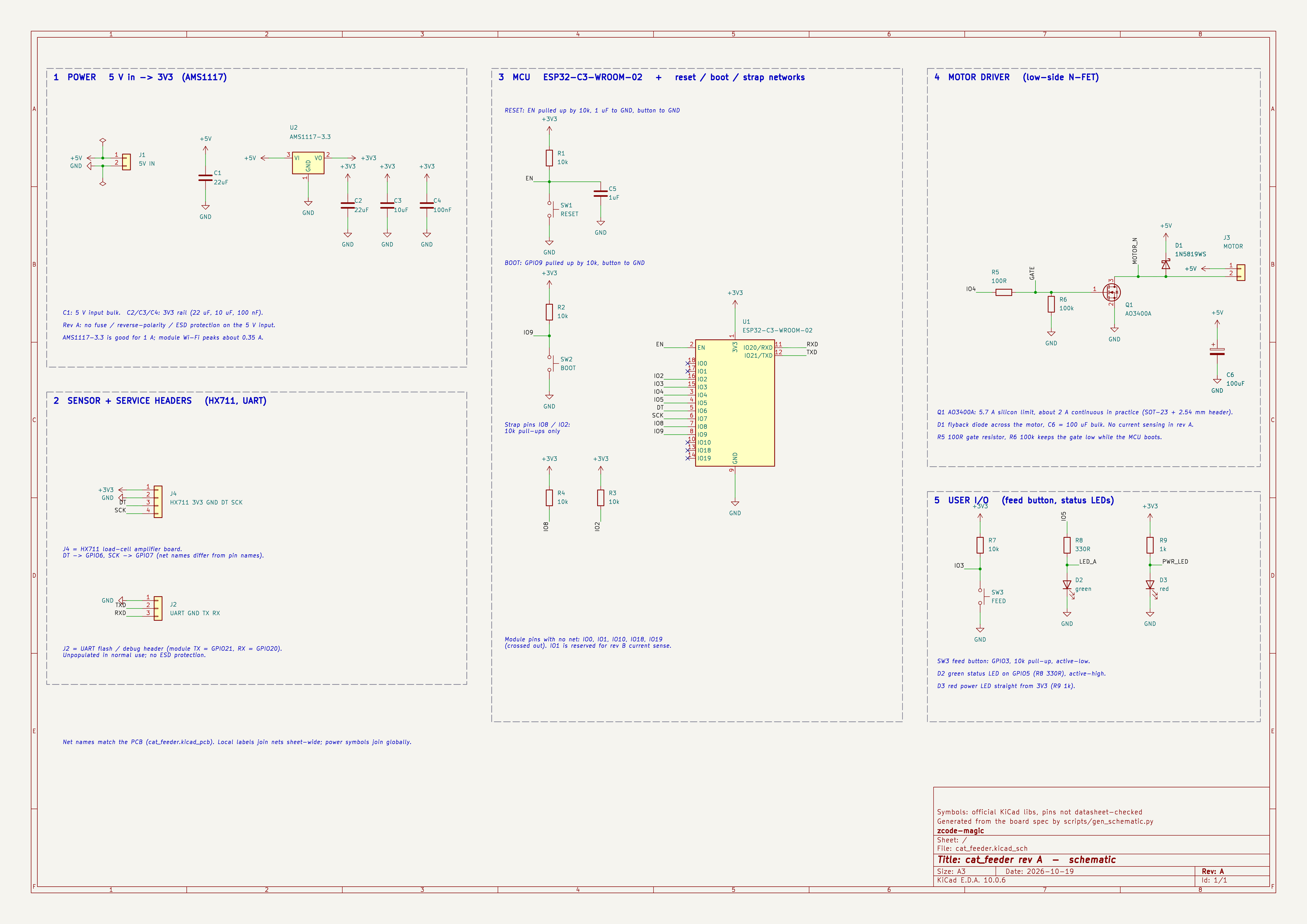
第一轮 Rev A(第二轮 Rev B 在 round-2/schematic/,多一个「6 电机电流检测」功能块):
| 文件 | 说明 |
|---|---|
round-1/schematic/cat_feeder.kicad_sch、round-2/schematic/cat_feeder_rev_b.kicad_sch | KiCad 10 原理图(A3)。和同目录的 .kicad_pro、库表放在一起,直接用 KiCad 打开 |
…_schematic.pdf / .svg / .png | 导出图(PNG 为 5040×3564) |
…_netlist.xml、erc_report.txt | 网表与 ERC 报告 |
round-1/schematic/easyeda/ | 流水线自动生成的 Rev A 嘉立创 EDA 工程包(.eprj3.zip)及其原理图渲染图 |
这些图是怎么来的:PCB 是直接从规格 JSON 生成的,流水线本身不出原理图
(引擎文档写明 "No schematic is generated")。所以原理图是事后用
tools/gen_schematic.py 按同一份规格画出来的:元件、取值、引脚、网络都来自规格,
符号取自官方 KiCad 库,只有摆放位置是手工定的。
已核对:
round-1/hardware/handed-off-to-jlc/cat_feeder.spec.json)的元件和网络完全一致;
Rev B 画图所用规格与订单包对应工程里的规格(cat_feeder_rev_b_kicad_project.zip 内的 spec)也完全一致;没有核对:符号的引脚名/编号来自 KiCad 官方库,没有对照数据手册(库里偶有错误)。
Rev A 嘉立创 EDA 工程包里自带的那张原理图(round-1/schematic/easyeda/cat_feeder_eprj3_sch_overview.png)是「网格摆一个个零件 + 网络标签」的机器布局,
大部分零件摆在图框外面,不是给人读的;它存在的目的是让 EDA 里有同一份网表。
重新生成:
python3 -I tools/gen_schematic.py round-1/hardware/cat_feeder_rev_a_spec.json out/ round-1/schematic/cat_feeder.kicad_pro
python3 -I tools/gen_schematic.py round-2/hardware/cat_feeder_rev_b_spec.json out/ round-2/schematic/cat_feeder_rev_b.kicad_pro --rev B
(需要 macOS 上安装的 KiCad 10;脚本里的路径是 /Applications/KiCad/KiCad.app。)
Rev A 的完整列表见 round-1/hardware/NOTES.md:没有电机电流检测;5 V 输入没有保险丝/防反接/ESD;
J1 与 J4 分别在板子左侧和中央,线缆会从三个方向进出;没有给元件映射嘉立创料号(LCSC)。
Rev B 解决了「电流检测」和「线缆方向」这两条,其余仍在,见 round-2/hardware/NOTES.md 和订单包。
docs/ 里的文档引用了一些没有放进本仓库的文件(JLC_NOTES.md、skills/… 等,属于驱动这条流水线的引擎仓库 fxp/zcode-magic,目前是私有的),那些链接在这里是断的。docs/05-hi3d-api-request.md 里的测试订单号已打码。| Qty | Value | Footprint | References |
|---|---|---|---|
| 5 | 10k | Resistor_SMD:R_0603_1608Metric | R1, R2, R3, R4, R7 |
| 4 | MountingHole_2.2mm | H1, H2, H3, H4 | |
| 3 | Fiducial | FID1, FID2, FID3 | |
| 2 | 22uF | Capacitor_SMD:C_0805_2012Metric | C1, C2 |
| 1 | 100R | Resistor_SMD:R_0603_1608Metric | R5 |
| 1 | 100k | Resistor_SMD:R_0603_1608Metric | R6 |
| 1 | 100nF | Capacitor_SMD:C_0603_1608Metric | C4 |
| 1 | 100uF | Capacitor_SMD:CP_Elec_6.3x5.4 | C6 |
| 1 | 10uF | Capacitor_SMD:C_0805_2012Metric | C3 |
| 1 | 1N5819WS | Diode_SMD:D_SOD-323 | D1 |
| 1 | 1k | Resistor_SMD:R_0603_1608Metric | R9 |
| 1 | 1uF | Capacitor_SMD:C_0603_1608Metric | C5 |
| 1 | 330R | Resistor_SMD:R_0603_1608Metric | R8 |
| 1 | 5V IN | Connector_PinHeader_2.54mm:PinHeader_1x02_P2.54mm_Vertical | J1 |
| 1 | AMS1117-3.3 | Package_TO_SOT_SMD:SOT-223-3_TabPin2 | U2 |
| 1 | AO3400A | Package_TO_SOT_SMD:SOT-23 | Q1 |
| 1 | BOOT | Button_Switch_SMD:SW_SPST_B3U-1000P | SW2 |
| 1 | ESP32-C3-WROOM-02 | RF_Module:ESP32-C3-WROOM-02 | U1 |
| 1 | FEED | Button_Switch_SMD:SW_SPST_B3U-1000P | SW3 |
| 1 | HX711 3V3 GND DT SCK | Connector_PinHeader_2.54mm:PinHeader_1x04_P2.54mm_Vertical | J4 |
| 1 | MOTOR | Connector_PinHeader_2.54mm:PinHeader_1x02_P2.54mm_Vertical | J3 |
| 1 | RESET | Button_Switch_SMD:SW_SPST_B3U-1000P | SW1 |
| 1 | UART GND TX RX | Connector_PinHeader_2.54mm:PinHeader_1x03_P2.54mm_Vertical | J2 |
| 1 | green | LED_SMD:LED_0603_1608Metric | D2 |
| 1 | red | LED_SMD:LED_0603_1608Metric | D3 |
It measures 66 × 60 mm and has 2 copper layers, 1.6 mm thick.
35 parts, built around the ESP32-C3-WROOM-02-H4, AMS1117-3.3, 1N5819WS and AO3400A. The full list of its parts is on this page, with links to each part's symbol and footprint where PCBKit's library has them.
From the fxp/cat-feeder repository on GitHub, at the commit this page was made from: the board is round-1/hardware/v2-jlc-bom/cat_feeder.kicad_pcb and its schematic round-1/schematic/cat_feeder.kicad_sch. PCBKit opens the board in the browser, with nothing to install.
Its repository states no licence, so its author keeps all rights: ask fxp before reusing the design.
jfryman/mw-cart
MegaWiFi Mega Drive/Genesis Wi-Fi cartridge — Rev.C fork (TI TL16C550D UART, 20 MHz / 1.25 Mbaud). Upstream: gitlab.com/doragasu/mw-cart

electro-practically/wled-controller
WLED ESP32 controller powered by USB-C Power Delivery.

thomaslr/plant-esp32
This directory contains the production files, Pick & Place centroid files (CPL), Bill of Materials (BOM), KiCad design source files, and 3D renders for the Monolithic Onboard SMD Edition of the Plant ESP32 watering…

0xjmux/iot_leddriver_hw
ESP32-based WS2812B LED Strip Driver PCB, designed for music visualization

Churrosoft/OpenEFI-PCB
Coleccion de PCB y planos recomendados para montar una OpenEFI

maximus64/opendiag-hardware
OpenDIAG - Open Source OBD2 Interface (Hardware)

Queens-Rocket-Engineering-Team/Avionics-23-26
QRET Avionics hardware, firmware, and documentation for 2023 to 2025.
