
2 layers
Particle counter
eigenlucy/spacebridgehabpcb
High Altitude Balloon Tracker, Telemetry, and Sensor Board
22 parts11

High Altitude Balloon Tracker, Telemetry, and Sensor Board
Layouts is an open-source printed circuit board by eigenlucy, from the eigenlucy/spacebridgehabpcb repository on GitHub. It is a 4-layer board of 37.6 × 39.4 mm with 52 parts on 77 nets, routed with 505 tracks and 80 vias.
Its parts include 15 capacitors, 13 resistors, 5 ICs, 3 transistors and 2 inductors. It belongs with the radio and wireless boards and the ESP32 boards of this library.
High Altitude Balloon (HAB) PCB Tracker with cutdown mechanism, GPS, environmental monitoring, LoRa telemetry and particle detection capabilities.
Created by Lucy Moglia eigenlucy@proton.me
The SpaceBridge HAB PCB is a comprehensive tracking and instrumentation system for high altitude balloon experiments. It integrates multiple subsystems including power management, telemetry, GPS tracking, environmental monitoring, and a particle counter based on CERN open source hardware.
| Module | Source File | PCB Layout | Description |
|---|---|---|---|
| Mainboard | mainboard.ato | layouts/default/default.kicad_pcb | Final PCB incorporating all submodules |
| MicroMPPT | micromppt/elec/src/micromppt.ato | micromppt/elec/layout/default/micromppt.kicad_pcb | 5W MPPT battery charger with embedded set point adjustment algorithm |
| Particle Counter | particle_counter.ato | layouts/particle-counter/particle-counter.kicad_pcb | Alpha particle detector based on CERN open source hardware kit |
| Cutoff Mechanism | cutoff.ato | layouts/cutoff/cutoff.kicad_pcb | Balloon cutoff circuit using lithium hybrid supercapacitor discharging through nichrome wire |
| BQ24045DSQR BMS | bq24045dsqr/elec/src/bq24045dsqr.ato | bq24045dsqr/elec/layout/default/bq24045dsqr.kicad_pcb | 5V 1A single cell LiPo/Li-ion charger + BMS |
| TPS63020DSJR | ~/.ato/modules/tps63020dsjr/elec/src/tps63020dsjr.ato | ~/.ato/modules/tps63020dsjr/elec/layout/tps63020dsjr.kicad_pcb | 1.8V-5.5V In/Out 4A boost-buck converter (5V from Vbat) |
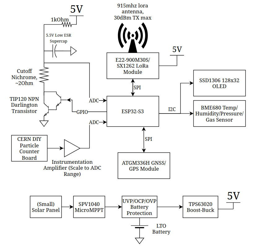
graph TD
    %% Power System
    Solar["Solar Panel"] --> MPPT["SPV1040 MicroMPPT"]
    MPPT --> BattProt["UVP/OCP/OVP Battery Protection"]
    BattProt --- Battery["LTO Battery"]
    BattProt --> BoostBuck["TPS63020 Boost-Buck"]
    BoostBuck --> Power5V["5V Power Rail"]

    %% ESP32 Microcontroller (Central)
    ESP32["ESP32-S3"]

    %% 5V Devices
    Power5V --> LoRa["E22-900M30S/SX1262 LoRa Module"]
    Power5V --> ParticleCounter["CERN DIY Particle Counter"]
    Power5V --> CutoffSystem["Cutoff System"]

    %% Cutoff System Components
    CutoffSystem --> Supercap["3.5V Low ESR Supercap"]
    CutoffSystem --> Nichrome["Nichrome Wire ~20Ω"]
    CutoffSystem --> TIP120["TIP120 NPN Darlington"]

    %% I2C Devices (3.3V)
    ESP32 -- I2C/IO6+IO7 --> OLED["SSD1306 128x32 OLED"]
ESP32 -- I2C/IO6+IO7 --> BME680["BME680 Sensor"]Clone the required submodules
git submodule update --init --recursiveBuild the project to select components based on JLCPCB availability
ato build -t allComplete/review the layout with KiCad Standalone PCB editor
Gerbers/PCBA files are generated through an Actions run on a commit
Install uv
Install KiCad with your preferred package manager (apt for Debian, pacman for Arch, etc.)
Install atopile as a tool with uv (Python 3.13.2 recommended):
uv tool install atopileAlternative installation method:
rm uv.lockuv sync --devuv builduv tool install atopile-0.3.XX-cp313-cp313-linux-_x86_64.whlfish_add_path /home/user/.local/share/uv/tools/atopile/Check your version:
ato --versionConfigure the atopile plugin:
ato configurebrew install --cask kicadbrew install atopile/tap/atopileato configureInstall the atopile extension into Cursor or Visual Studio Code.
| Qty | Value | Footprint | References |
|---|---|---|---|
| 8 | 10kΩ ±1% 62.5mW | atopile:R0402-56259e | R2, R3, R4, R7, R8, R9, R14, R15 |
| 7 | 100nF ±10% 16V X7R | atopile:C0402-b3ef17 | C2, C03, C4, C5, C6, C11, C22 |
| 3 | atopile:CONN-TH_XH-2A-b4a6f6 | BATTERY, CUTOFF, HEATER | |
| 3 | 100nF ±10% 50V X7R | atopile:C0603-bd72f6 | C3, C23, C24 |
| 2 | atopile:SOT-23-3_L2.9-W1.3-P1.90-LS2.4-BR-688f29 | Q1, Q3 | |
| 2 | atopile:CONN-SMD_BM04B-SRSS-TB-6963ef | I2C, I2C2 | |
| 2 | 100nF ±10% 50V X7R | atopile:C0805-3b2e55 | C10, C30 |
| 2 | 10µF ±10% 25V X5R | atopile:C0805-3b2e55 | C01, C112 |
| 2 | 5.1kΩ ±1% 62.5mW | atopile:R0402-56259e | U19, U29 |
| 1 | atopile:CONN-SMD_7P-P1.00_BM07B-SRSS-TB-201aba | GPIO | |
| 1 | atopile:SOP-6_L7.0-W7.0-P2.54-LS10.3-BL-0df1ed | U1 | |
| 1 | atopile:SMA_L4.3-W2.6-LS5.2-RD-e14692 | D2 | |
| 1 | atopile:R0201-27027e | R6 | |
| 1 | atopile:LGA-8_L3.0-W3.0-P0.80_BME688-7465bb | U3 | |
| 1 | atopile:CAP-TH_BD8.0-P3.50-D0.6-FD_1-b17e9d | C1 | |
| 1 | lib:KEY-SMD_4P-L4.2-W3.2-P2.20-LS4.6 | RESET | |
| 1 | atopile:DFN-8_L3.3-W3.3-P0.65-BL-2-bd6bc9 | Q2 | |
| 1 | atopile:WIRELM-SMD_E22-900M22S-72e54e | LORA | |
| 1 | atopile:BAT-SMD_C238096-012a28 | BAT1 | |
| 1 | atopile:L0201-8d2bbc | L2 | |
| 1 | lib:WIRELM-SMD_ESP32-S3-WROOM-1 | ESP32S3 | |
| 1 | atopile:IND-SMD_L3.0-W3.0-a13401 | L1 | |
| 1 | lib:USB-C-SMD_KH-TYPE-C-16P | USBC | |
| 1 | atopile:IPEX-SMD_4P-L2.6-W2.6-LS3.0-f1620f | G_ANT | |
| 1 | atopile:SOT-23-5_L3.0-W1.7-P0.95-LS2.8-BR-9d80aa | U26 | |
| 1 | atopile:GPSM-SMD_ATGM336H-TR-d79f58 | GPS | |
| 1 | 10kΩ ±1% 125mW | atopile:R0805-c79e8b | R1 |
| 1 | 10kΩ ±1% 50mW | atopile:R0201-27027e | R5 |
| 1 | 200kΩ ±1% 62.5mW | atopile:R0402-56259e | R20 |
| 1 | 887kΩ ±1% 62.5mW | atopile:R0402-56259e | R21 |
It measures 37.6 × 39.4 mm and has 4 copper layers, 1.6 mm thick.
52 parts. The full list of its parts is on this page, with links to each part's symbol and footprint where PCBKit's library has them.
From the eigenlucy/spacebridgehabpcb repository on GitHub, at the commit this page was made from: the board is layouts/default/default.kicad_pcb and its schematic ams1117-33/elec/layout/default/ams1117-33.kicad_sch. PCBKit opens the board in the browser, with nothing to install.
Its repository states no licence, so its author keeps all rights: ask eigenlucy before reusing the design.
eigenlucy/spacebridgehabpcb
High Altitude Balloon Tracker, Telemetry, and Sensor Board

eigenlucy/spacebridgehabpcb
High Altitude Balloon Tracker, Telemetry, and Sensor Board

willem-pennings/balancing-cube
A cube that balances itself in a corner or edge using reaction wheels

hackclub/OnBoard
💡 Join 1,000 teenagers and make your first PCB with a $100 grant!

Arrow-air/project-quiver
Project Quiver documentation, designs, and project artifacts.

Seeed-Studio/OSHW-reCamera-Series
reCamera is a series of open-source AI cameras.


macaba/TheManhattanToolkit
Input R - RNCF0603DTE10R0 (10 ohm) Input CM C - CGA3E1C0G2A472J080AC (4.7nF) Input DM C - DNP

jbilander/SF500
Spitfire 500, A low-end 14 MHz Accelerator with IDE and 4/8 MB fast RAM for the Amiga 500.

jncronin/gk
This respository provides PCB schematics, firmware and debugging support for the gkv4 handheld game console and its operating system, gkos. For the original STM32H7S7-based gk, see README-v3.md.