6 layers150 × 122 mm
Brain drain
dmz006/brain-drain
Standalone four-bay (plus M.2) NIST 800-88 disk sanitizer: Raspberry Pi CM5 carrier board, Python service, 3D-printed enclosure
167 parts2

 dmz006/brain-drain2
Standalone four-bay (plus M.2) NIST 800-88 disk sanitizer: Raspberry Pi CM5 carrier board, Python service, 3D-printed enclosure
Board v3-83pct is an open-source printed circuit board by dmz006, from the dmz006/brain-drain repository on GitHub. It is a 4-layer board of 150 × 112 mm with 302 parts on 260 nets, routed with 3,300 tracks and 738 vias.
It is built around the TPS56637RPAR, USB5744/2G and ASM1153E, with the M2.5, AO4407A and CR2032 among its other parts. Its parts include 148 capacitors, 72 resistors, 17 transistors, 13 ICs and 12 connectors. It belongs with the computers and single-board computers boards of this library.


Two KiCad 9 projects, both generated from tools/design.py (see ../docs/LAYOUT-REVIEW.md for how, and for what a
layout engineer must check). Design intent: ../docs/ARCHITECTURE.md section 3. Parts: ../docs/BOM.md.
Regenerate and route commands: ../docs/USAGE.md.
| Brain board | Bay card | |
|---|---|---|
| Project | brain-drain.kicad_pro | bay-card/bay-card.kicad_pro |
| Size, layers | 150 x 122 mm, 6 layers (F sig, In1 GND, In2 sig, In3 sig, In4 power, B sig), 1.6 mm, ENIG | 45 x 46 mm, 4 layers (F sig, In1 GND, In2 power, B sig), 1.6 mm, ENIG, finger tab |
| Contents | CM5 wireless, two USB5744 hubs, eight PCIe x1 bay slots, M.2 socket, 12 V input and bucks, OLED and DIP headers, LEDs, microSD, USB-C | ASM1153E bridge, two P-FET power switches with PTC fuses, SATA 22-pin receptacle, PCIe x1 fingers |
| Schematic sheets | power-input, power-bucks, cm5, usb3-hub-A, usb3-hub-B, bay-slots, m2-nvme | bridge, bay-switch, edge |
| Status | routed: 0 open connections, 0 DRC errors, 44 pairs matched | routed: 0 open connections, 0 DRC errors, 8 pairs matched |
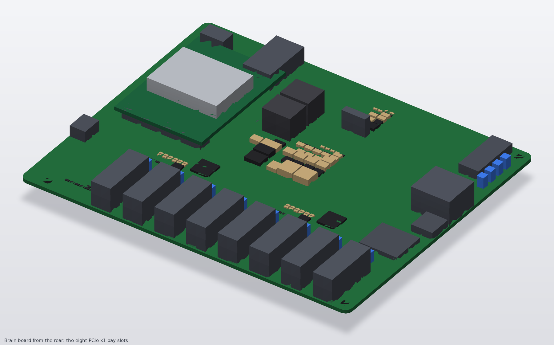
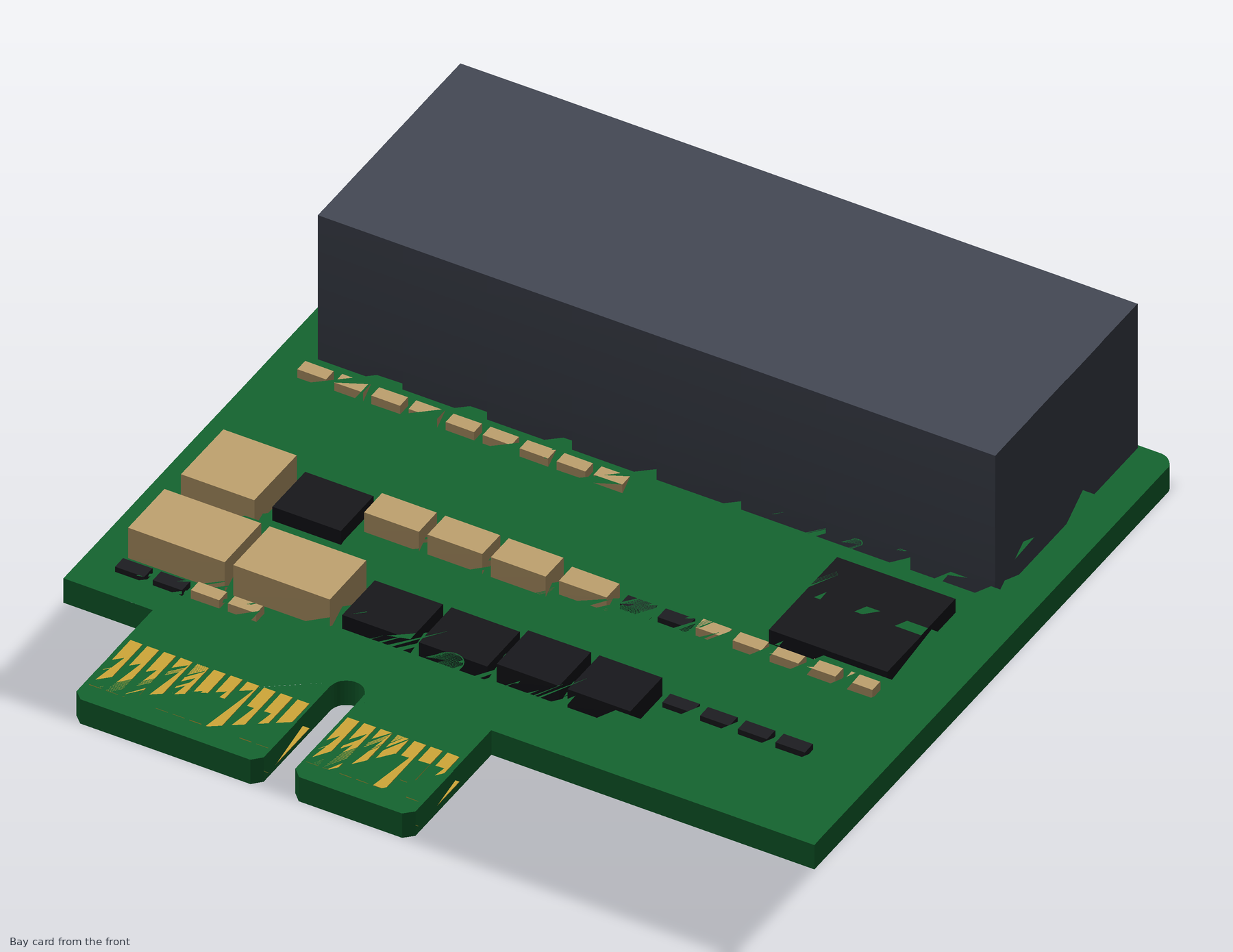
More views and the assembled unit: ../docs/RENDERS.md. KiCad's own 3D views are in renders/, one image per layer in
renders/layers/ (F.Cu, In1 to In4, B.Cu, assembly-top, assembly-bottom, mask), schematic sheets in renders/schematic/.
hardware/
  brain-drain.kicad_pro / .kicad_sch / .kicad_pcb   the brain (generated; the PCB also carries the routing)
  sheets/*.kicad_sch                                7 brain sheets (generated)
  bay-card/                                         the bay card project, same layout: .kicad_pro/.sch/.pcb, sheets/, routing/, renders/
  CONNECTIONS.md, bay-card/CONNECTIONS.md           net-by-net connection lists (generated)
  lib/brain-drain.kicad_sym, lib/brain-drain.pretty custom symbols and footprints (see lib/brain-drain.pretty/README.md for origins)
  review/                                           generated review pack: design rules, stack-up, planes, keep-outs, routing statistics,
                                                    DRC / ERC summaries, footprint provenance, netlists, placement CSV, schematic PDFs
  routing/, bay-card/routing/                       Specctra DSN/SES for freerouting, drc.json, open.md, pairs.md, chain.log
  renders/, bay-card/renders/                       KiCad 3D views, per-layer PNGs, schematic PNGs and PDFs
  bom/                                              brain-drain-bom.csv, bay-card-bom.csv (generated)
  ref/                                              pin tables (CSV), DOWNLOADS.md; ref/datasheets/ is gitignored
  tools/                                            the generators and the routing pipeline, listed in ../docs/LAYOUT-REVIEW.md section 6
fab/ fab/<date>/ order packs (gitignored)route.py prepare; the table is in review/design-rules.md.DiffPair90 is 0.147 mm / 0.253 mm gap, carried over from a four-layer
design and not yet recalculated for the six-layer stack-up. Pairs are length-matched end to end (across the series capacitors) to 0.15 mm.keepout_CM5_antenna); keep-outs around the CM5's four standoff holes.BAY_EN, on the card).See ../docs/LAYOUT-REVIEW.md (priority items and the sign-off checklist) and ../docs/STATUS.md R2, R3, R10, R25 to R30: the stack-up and pair geometry, the M.2 footprint against the TE drawing, the Molex face position, the DIN pinout from the chosen brick, test points, fiducials and ESD, the card panel.
Any Linux box plus an ASM1153E-based USB dock answers the risky questions: does hdparm --sanitize-* pass through, does the bridge survive a long SECURITY ERASE,
does --sanitize-status report progress. A Pi 5 with two docks is the exact software test bed for this topology. Do this first
(../docs/saturday-bench-plan.md).
| Qty | Value | Footprint | References |
|---|---|---|---|
| 68 | 100n | Capacitor_SMD:C_0402_1005Metric | C110, C111, C1006, C1007, C1008, C1009, C1010, C1011, C1020, C1021, C1106, C1107, C1108, C1109, C1110, C1111 +52 |
| 37 | 10k | Resistor_SMD:R_0402_1005Metric | R10, R11, R101, R102, R113, R114, R123, R124, R201, R202, R1001, R1101, R1201, R1301, R2001, R2003 +21 |
| 16 | 10n | Capacitor_SMD:C_0402_1005Metric | C1030, C1031, C1032, C1033, C1130, C1131, C1132, C1133, C1230, C1231, C1232, C1233, C1330, C1331, C1332, C1333 |
| 15 | 10u 10V | Capacitor_SMD:C_0805_2012Metric | C3, C31, C500, C1003, C1004, C1005, C1103, C1104, C1105, C1203, C1204, C1205, C1303, C1304, C1305 |
| 13 | 22u 10V | Capacitor_SMD:C_0805_2012Metric | C1, C2, C501, C2003, C2004, C2005, C2103, C2104, C2105, C2202, C2203, C5102, C5103 |
| 10 | 100k | Resistor_SMD:R_0402_1005Metric | R310, R320, R330, R340, R410, R420, R430, R440, R2002, R2102 |
| 8 | 22p | Capacitor_SMD:C_0402_1005Metric | C1000, C1001, C1100, C1101, C1200, C1201, C1300, C1301 |
| 8 | 2N7002 | Package_TO_SOT_SMD:SOT-23 | Q51, Q52, Q53, Q54, Q61, Q62, Q63, Q64 |
| 8 | P-FET -30V 6A DFN3x3 | Package_DFN_QFN:DFN-8-1EP_3x3mm_P0.65mm_EP1.5x2.25mm | Q31, Q32, Q33, Q34, Q41, Q42, Q43, Q44 |
| 7 | 10u 25V | Capacitor_SMD:C_1210_3225Metric | C22, C2000, C2001, C2100, C2101, C2200, C5100 |
| 5 | 470 | Resistor_SMD:R_0402_1005Metric | R505, R1002, R1102, R1202, R1302 |
| 4 | 12.1k 1% | Resistor_SMD:R_0402_1005Metric | R1000, R1100, R1200, R1300 |
| 4 | 1k | Resistor_SMD:R_0402_1005Metric | R511, R521, R531, R541 |
| 4 | 2.2u | Capacitor_SMD:C_0603_1608Metric | C1002, C1102, C1202, C1302 |
| 4 | 2A hold 1812 | Fuse:Fuse_1812_4532Metric | F14, F15, F16, F17 |
| 4 | 30MHz CL=16pF | Crystal:Crystal_SMD_3225-4Pin_3.2x2.5mm | Y10, Y11, Y12, Y13 |
| 4 | 33p | Capacitor_SMD:C_0402_1005Metric | C100, C101, C200, C201 |
| 4 | 3A hold 1812 | Fuse:Fuse_1812_4532Metric | F10, F11, F12, F13 |
| 4 | 4.7u 10V | Capacitor_SMD:C_0603_1608Metric | C130, C131, C230, C231 |
| 4 | 4.7u 1A | Inductor_SMD:L_Taiyo-Yuden_NR-40xx | L10, L11, L12, L13 |
| 4 | ASM1153E | Package_DFN_QFN:QFN-48-1EP_6x6mm_P0.4mm_EP4.6x4.6mm | U10, U11, U12, U13 |
| 4 | SATA 22-pin | brain-drain:SATA_22pin_Receptacle_RA | J10, J11, J12, J13 |
| 4 | blue bay activity | LED_THT:LED_D3.0mm | D10, D11, D12, D13 |
| 3 | 1k | Resistor_SMD:R_0603_1608Metric | R1, R2, R3 |
| 3 | M2.5 | MountingHole:MountingHole_2.7mm_M2.5 | H1, H2, H3 |
| 2 | 0R (cap DNP alt) | Capacitor_SMD:C_0402_1005Metric | R502, R503 |
| 2 | 100n 10V | Capacitor_SMD:C_0402_1005Metric | C2201, C5101 |
| 2 | 100n 25V | Capacitor_SMD:C_0402_1005Metric | C2002, C2102 |
| 2 | 12.0k 1% | Resistor_SMD:R_0402_1005Metric | R100, R200 |
| 2 | 1u 10V | Capacitor_SMD:C_0402_1005Metric | C4, C30 |
| 2 | 2.2u 8A | Inductor_SMD:L_Taiyo-Yuden_NR-60xx | L20, L21 |
| 2 | 200k | Resistor_SMD:R_0402_1005Metric | R103, R203 |
| 2 | 25MHz CL=20pF | Crystal:Crystal_SMD_3225-4Pin_3.2x2.5mm | Y1, Y2 |
| 2 | 4.7u 3A | Inductor_SMD:L_Taiyo-Yuden_NR-40xx | L22, L51 |
| 2 | 680u 25V low-ESR | Capacitor_SMD:CP_Elec_10x10.5 | C20, C21 |
| 2 | 73.2k | Resistor_SMD:R_0402_1005Metric | R2000, R2100 |
| 2 | AP63203WU-7 | Package_TO_SOT_SMD:TSOT-23-6 | U22, U51 |
| 2 | TPS22965DSGR | Package_SON:Texas_DSG0008A_WSON-8-1EP_2x2mm_P0.5mm_EP0.9x1.6mm | U50, U52 |
| 2 | TPS56637RPAR | brain-drain:Texas_RPA0010A_VQFN-HR-10_3x3mm | U20, U21 |
| 2 | USB5744/2G | Package_DFN_QFN:QFN-56-1EP_7x7mm_P0.4mm_EP3.2x3.2mm | U1, U2 |
| 1 | 100k | Resistor_SMD:R_0603_1608Metric | R20 |
| 1 | 10A slow 0453010.MR | Fuse:Fuse_Littelfuse-NANO2-451_453 | F1 |
| 1 | 12V 0.5W | Diode_SMD:D_SOD-123 | D21 |
| 1 | 1n | Capacitor_SMD:C_0402_1005Metric | C502 |
| 1 | AO4407A | Package_SO:SOIC-8_3.9x4.9mm_P1.27mm | Q20 |
| 1 | AP2112K-1.2 | Package_TO_SOT_SMD:SOT-23-5 | U3 |
| 1 | CM5002016 | brain-drain:Raspberry-Pi-5-Compute-Module | M1 |
| 1 | CR2032 | Battery:BatteryHolder_Keystone_1060_1x2032 | BT1 |
| 1 | DIP x8 | Button_Switch_THT:SW_DIP_SPSTx08_Piano_10.8x21.88mm_W7.62mm_P2.54mm | SW1 |
| 1 | Fan GND/5V/TACH/PWM | Connector:FanPinHeader_1x04_P2.54mm_Vertical | J40 |
| 1 | KPJX-4S-S | brain-drain:Kycon_KPJX-4S-S | J21 |
| 1 | M.2 M-key | brain-drain:M2_Socket3_MKey_CM5IO | J50 |
| 1 | OLED GND/VCC/SCL/SDA | Connector_PinHeader_2.54mm:PinHeader_1x04_P2.54mm_Vertical | J41 |
| 1 | SMBJ15A | Diode_SMD:D_SMB | D20 |
| 1 | UART0 GND/TX/RX | Connector_PinHeader_2.54mm:PinHeader_1x03_P2.54mm_Vertical | J7 |
| 1 | USB-C rpiboot | Connector_USB:USB_C_Receptacle_GCT_USB4085 | J5 |
| 1 | blue M.2 activity | LED_THT:LED_D3.0mm | D50 |
| 1 | green ACT | LED_THT:LED_D3.0mm | D2 |
| 1 | green PWR | LED_THT:LED_D3.0mm | D1 |
| 1 | lid microswitch | Button_Switch_THT:SW_PUSH_6mm | SW3 |
| 1 | microSD | Connector_Card:microSD_HC_Hirose_DM3AT-SF-PEJM5 | J3 |
| 1 | nRPIBOOT | Connector_PinHeader_2.54mm:PinHeader_1x02_P2.54mm_Vertical | J6 |
| 1 | red STATUS | LED_THT:LED_D3.0mm | D3 |
dmz006/brain-drain
Standalone four-bay (plus M.2) NIST 800-88 disk sanitizer: Raspberry Pi CM5 carrier board, Python service, 3D-printed enclosure

dmz006/brain-drain
Standalone four-bay (plus M.2) NIST 800-88 disk sanitizer: Raspberry Pi CM5 carrier board, Python service, 3D-printed enclosure

EdgeOfAssembly/multi-hdd-usb3-adapter
USB3 multi-HDD adapter (PATA+SATA) — JLCPCB Gerbers/BOM

bluesatunsw/owr
This repo includes all software necessary to operate the Test Rover Platform that is being designed and developed in the 502 project.


lapalmaelettronica/Progetti
Una lista dei progetti che ho pubblicato su instagram, potete trovarci pcb, codici, schemo elettrici e stampe 3d!


Brickteam-RO/tilting-maze
STM32-powered real-time maze generator and solver built for the Robochallenge 2026 - Freestyle Showcase University competition

It measures 150 × 112 mm and has 4 copper layers, 1.6 mm thick.
302 parts, built around the TPS56637RPAR, USB5744/2G, ASM1153E and M2.5. The full list of its parts is on this page, with links to each part's symbol and footprint where PCBKit's library has them.
From the dmz006/brain-drain repository on GitHub, at the commit this page was made from: the board is hardware/routing/board-v3-83pct.kicad_pcb and its schematic hardware/bay-card/bay-card.kicad_sch. PCBKit opens the board in the browser, with nothing to install.
Its repository states no licence, so its author keeps all rights: ask dmz006 before reusing the design.