2 layers69.9 × 55.9 mm
Smartportsd nano shield
djtersteegc/smartportsd
Various PCB and case designs of the SmartPortSD hard disk emulator for Apple II computers.
18 parts54MIT

 djtersteegc/smartportsd54
Various PCB and case designs of the SmartPortSD hard disk emulator for Apple II computers.
Smartportsd smd is an open-source printed circuit board by djtersteegc, from the djtersteegc/smartportsd repository on GitHub, published under the MIT licence. It is a 2-layer board of 41 × 50 mm with 25 parts on 40 nets, routed with 241 tracks and 68 vias.
It is built around the ATMEGA328P-AU and AMS1117-3.3. Its parts include 8 capacitors, 8 resistors, 3 ICs, 3 connectors and 1 diode. It belongs with the AVR (ATmega, ATtiny) boards of this library.


There's an interactive BOM here, and CSV version with footprint info here. The interactive one is super useful when placing the SMD components.
C5 is an optional bulk capacitor for the 5V power rail near the MCU. In my experience building these it is not needed.
The SD card connector is commonly available from several different Chinese suppliers and often called "long body", "non popping", or "push pull" on AliExpress or eBay.
https://www.aliexpress.us/item/3256805779248826.html
Here's some links on LCSC.
https://www.lcsc.com/product-detail/SD-Card-Connectors_Hanbo-Electronic-SD-112_C961673.html
https://www.lcsc.com/product-detail/SD-Card-Connectors_XUNPU-SD-102_C266602.html
https://www.lcsc.com/product-detail/SD-Card-Connectors_Megastar-ZX-SD-282-8Y_C7419835.html
It should also cross with a Wurth 693063010911 or AMP GSD090012SEU if you want something domestically.
The pins for the DB19 connector can be purchased from this seller on AliExpress, https://www.aliexpress.us/item/3256802431271655.html Ideally I would have used the "PCB Plug" model if they stocked them which are similar to the TE/AMP 5-745287-4 model mozzwald used on the FujiApple DB19 to IDC20 adapters, but these are much more cost effective and work just as well once assembled.
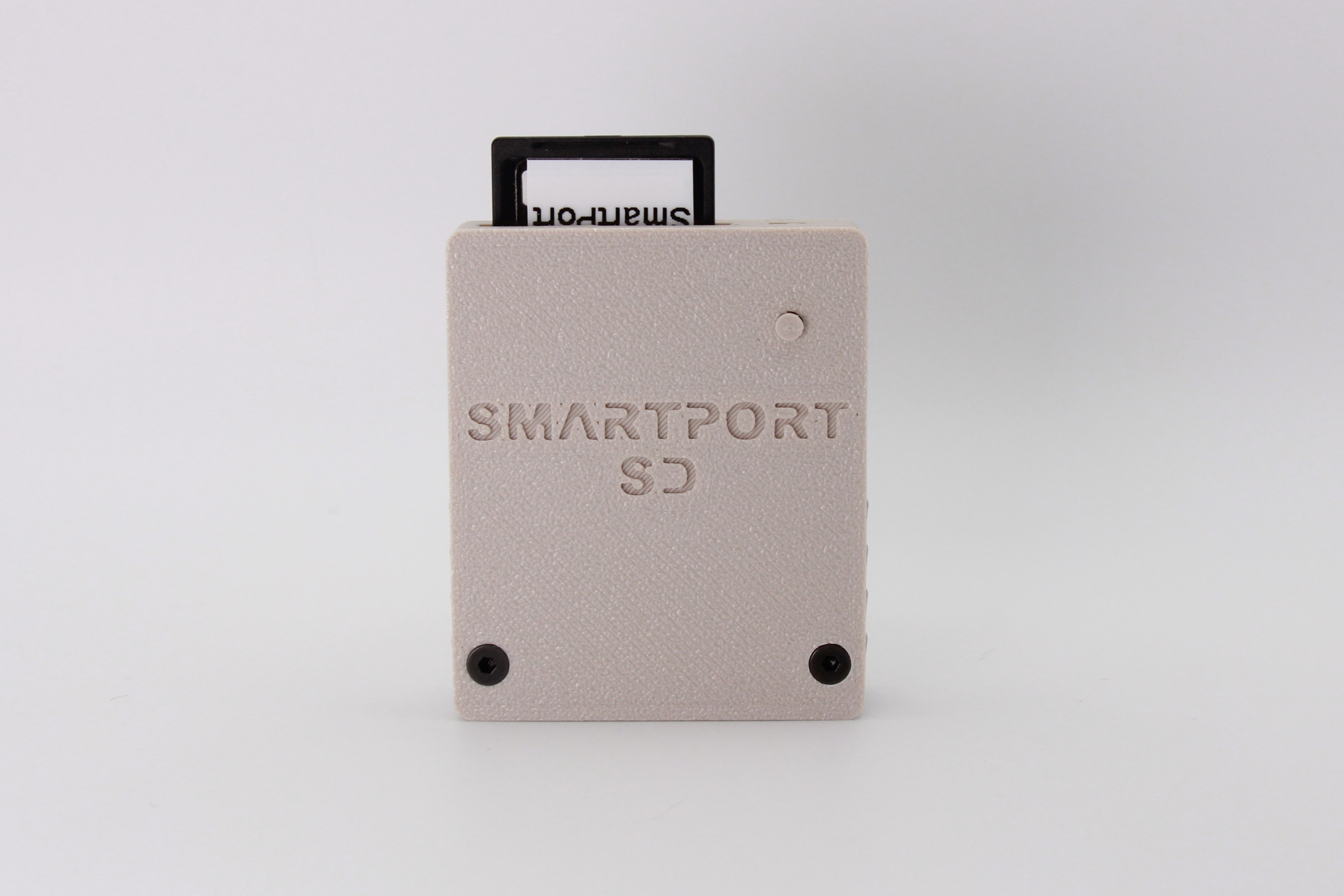
The case was created in DesignSpark and the design file is available if you would like to modify it further.
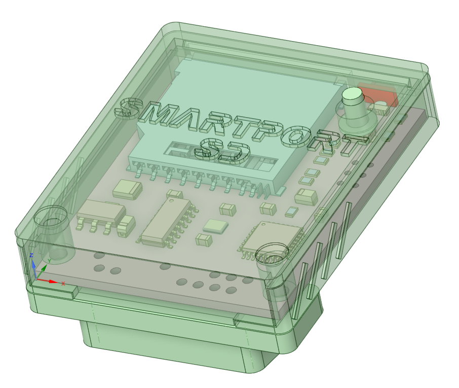
There is a single light pipe that should be printed in transparent material, or you can just leave it off completely. The case is designed to be printed at 0.2mm layer heights and assembled with two M2.5x14mm screws through the connector body and two M2.5 nuts pushed into either the handle or lid.
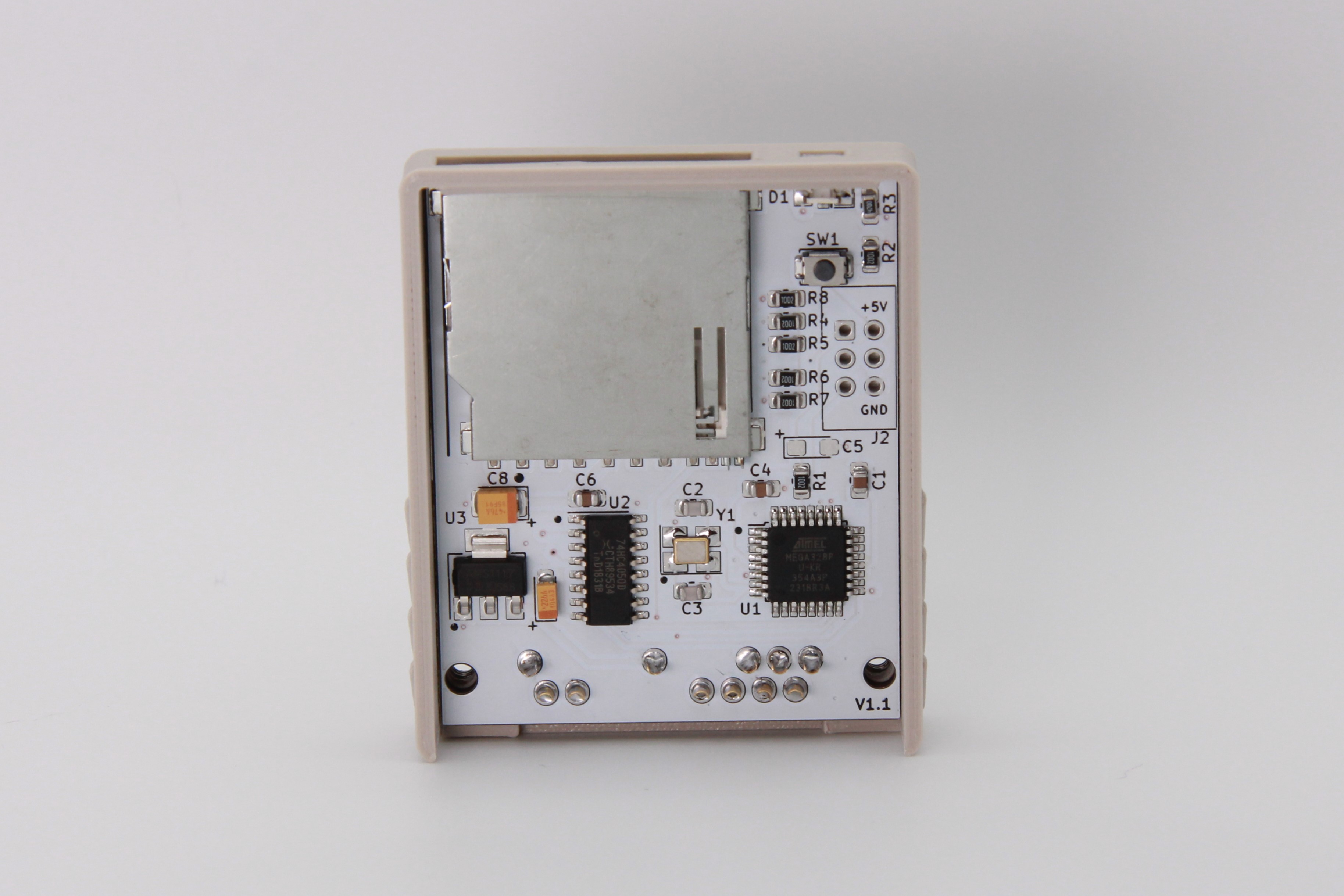
Assemble all the SMD components. I use solder paste hand applied with a pneumatic dispenser and then finish on a hot plate. But you can also hand solder, use hot air, or even order a stencil for paste application and use a proper reflow oven. I use a red LED for the activity indicator. Make sure to observe polarity with the green stripe on the LED to the right matching the white stripe on the PCB silkscreen.
For the ATMEGA328P chip I did use part of stencil I had from a previous project with the same footprint, or you can buy one from Amazon. Cheaper than ordering a whole stencil from somewhere like JLCPCB once you factor in shipping costs.
Do NOT install the 2x3 ICSP pin header at J2. I would recommend flashing the firmware at this point to do basic checks since it's easier to do board rework before you install the DB19 pins.
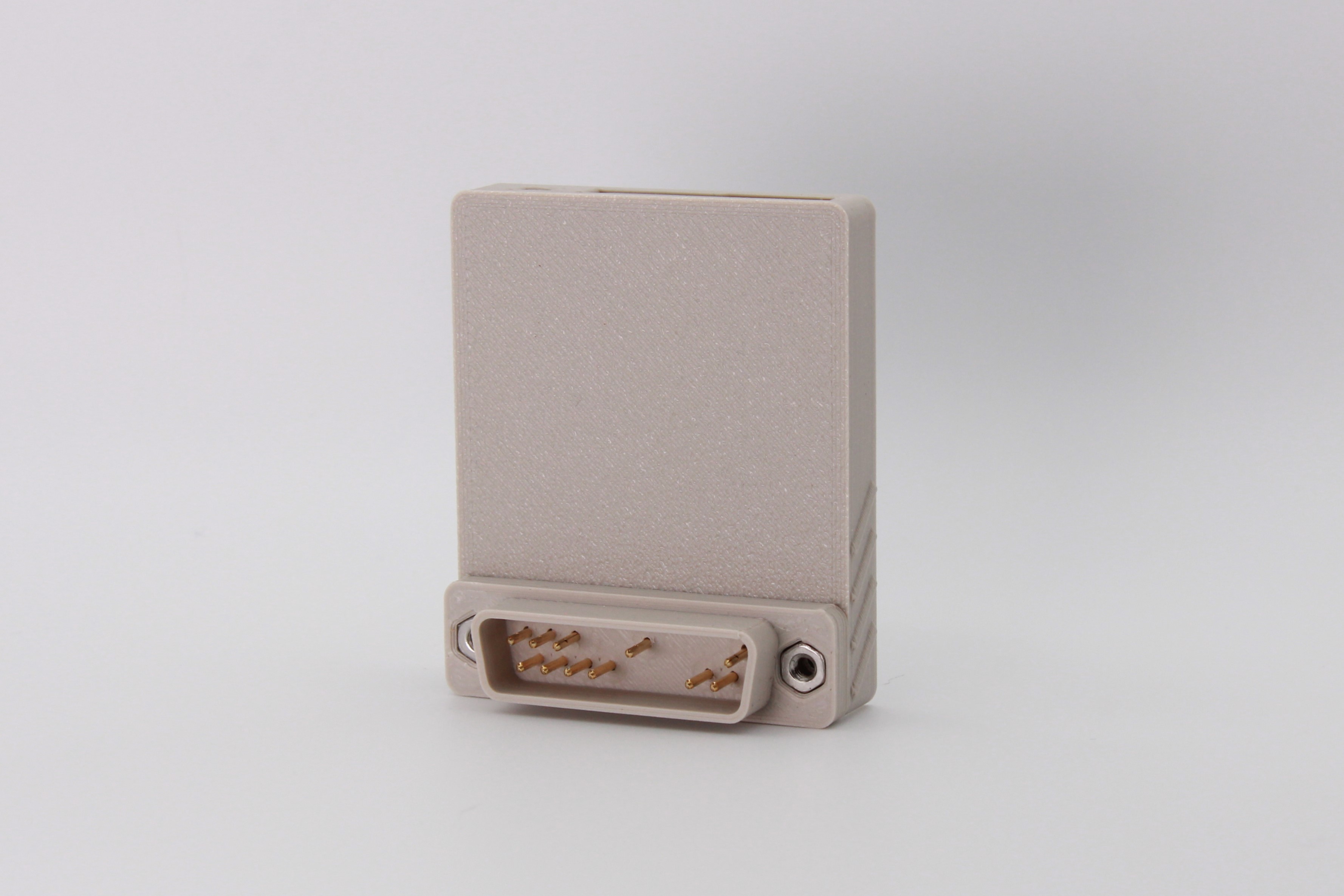
To install the connector, first take your printed DB19 shell and use a 1.0mm and 2.0mm drill bit to properly size the holes. I use a cut down DB25 connector to hold the pins straight while soldering. It also makes a nice way to hold everything in a vise.
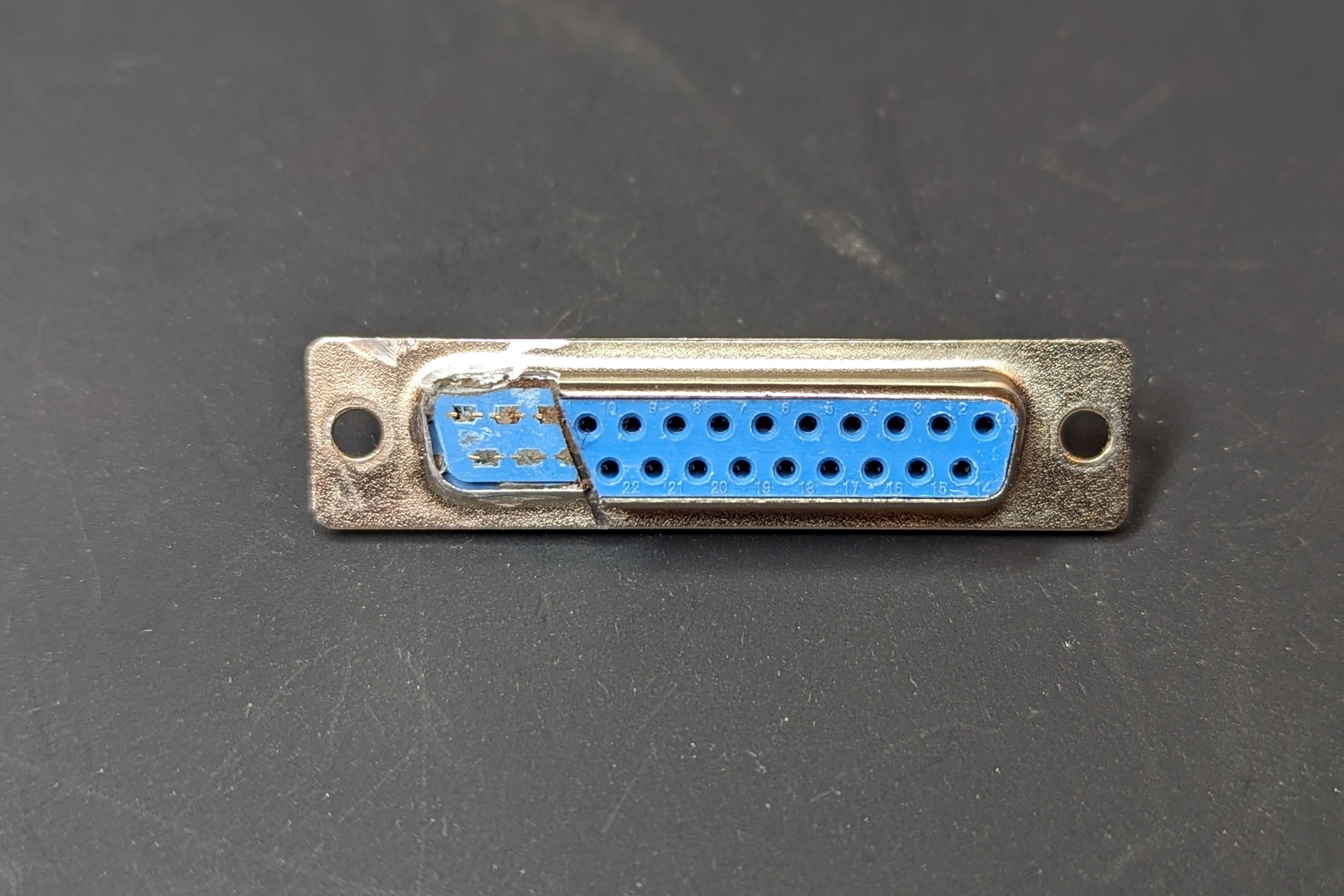
Insert the pins and case shell through the case back and assemble with short M2.5 screws. Tighten the screws gently so you can still slide out the case in the future if needed and then solder the pins. Ensure the tops of all the pins are even and the bottom of the solder cup on the pins should be close to even with the PCB.
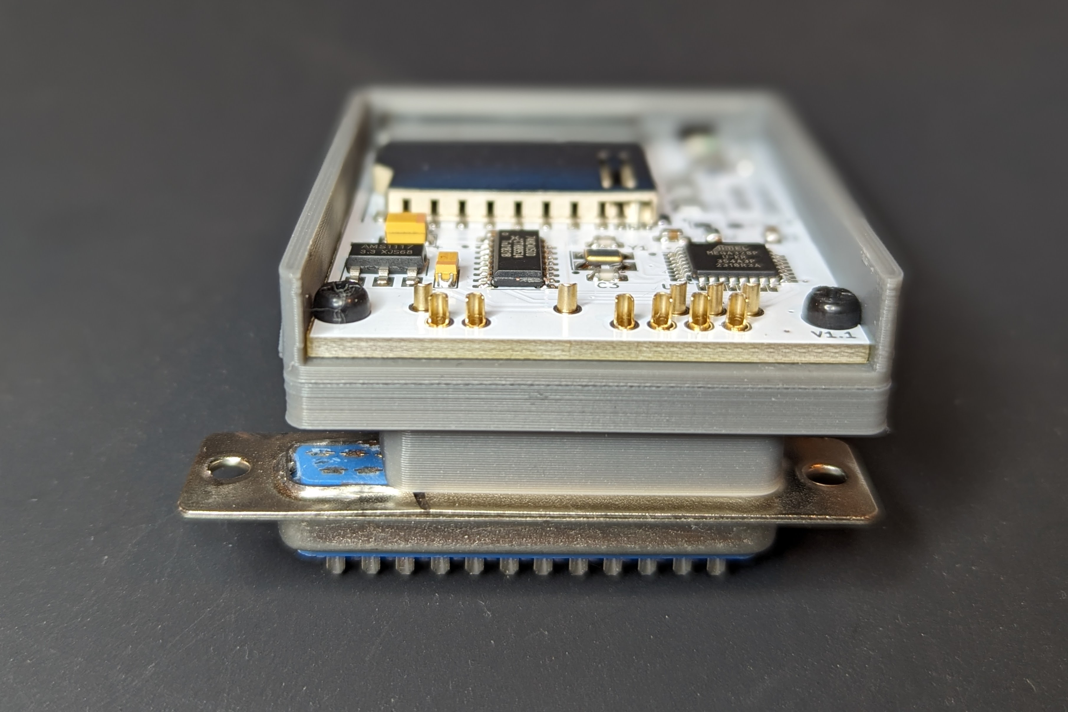
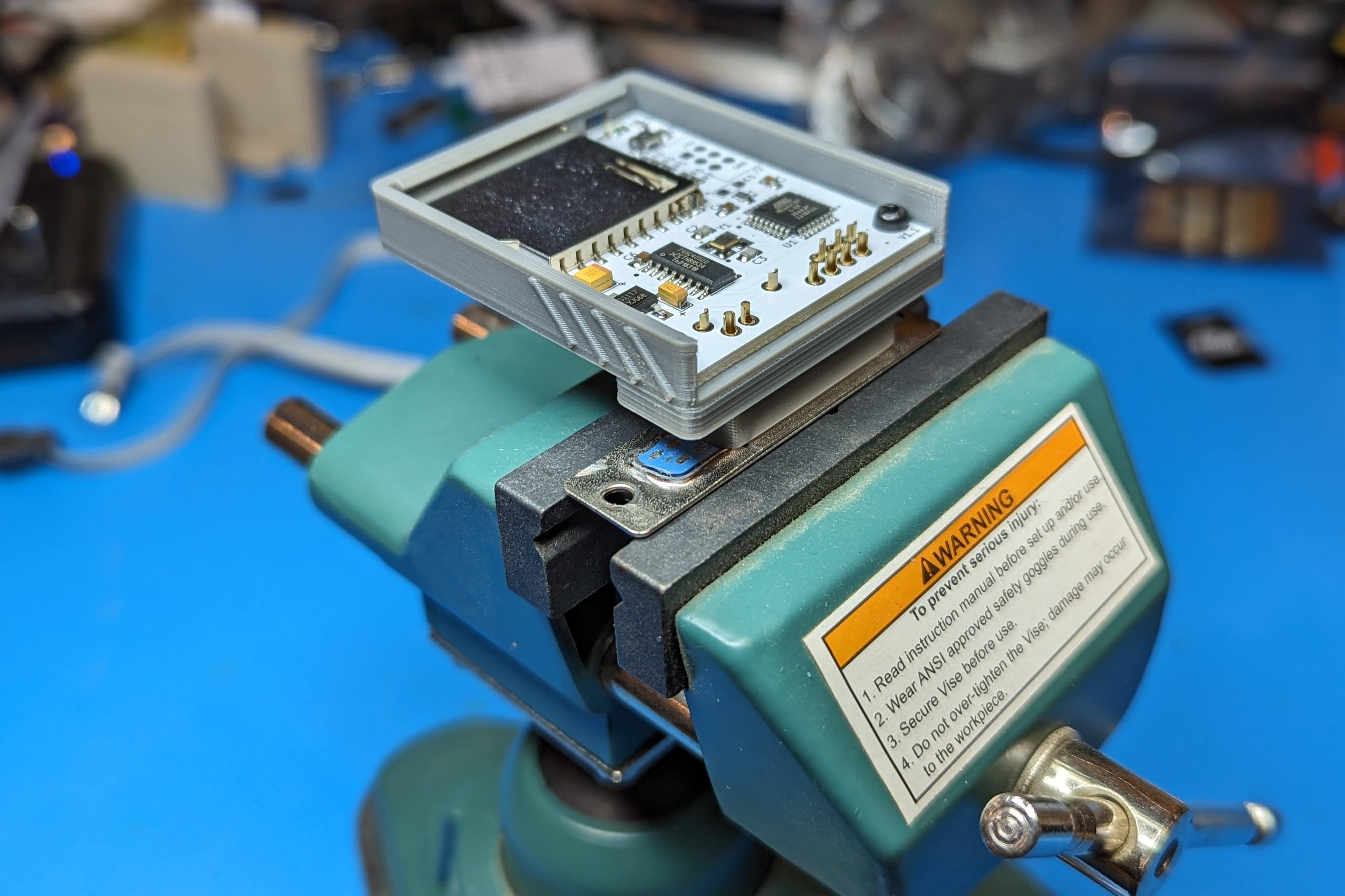
When complete it should look something like this when slid out of the case.
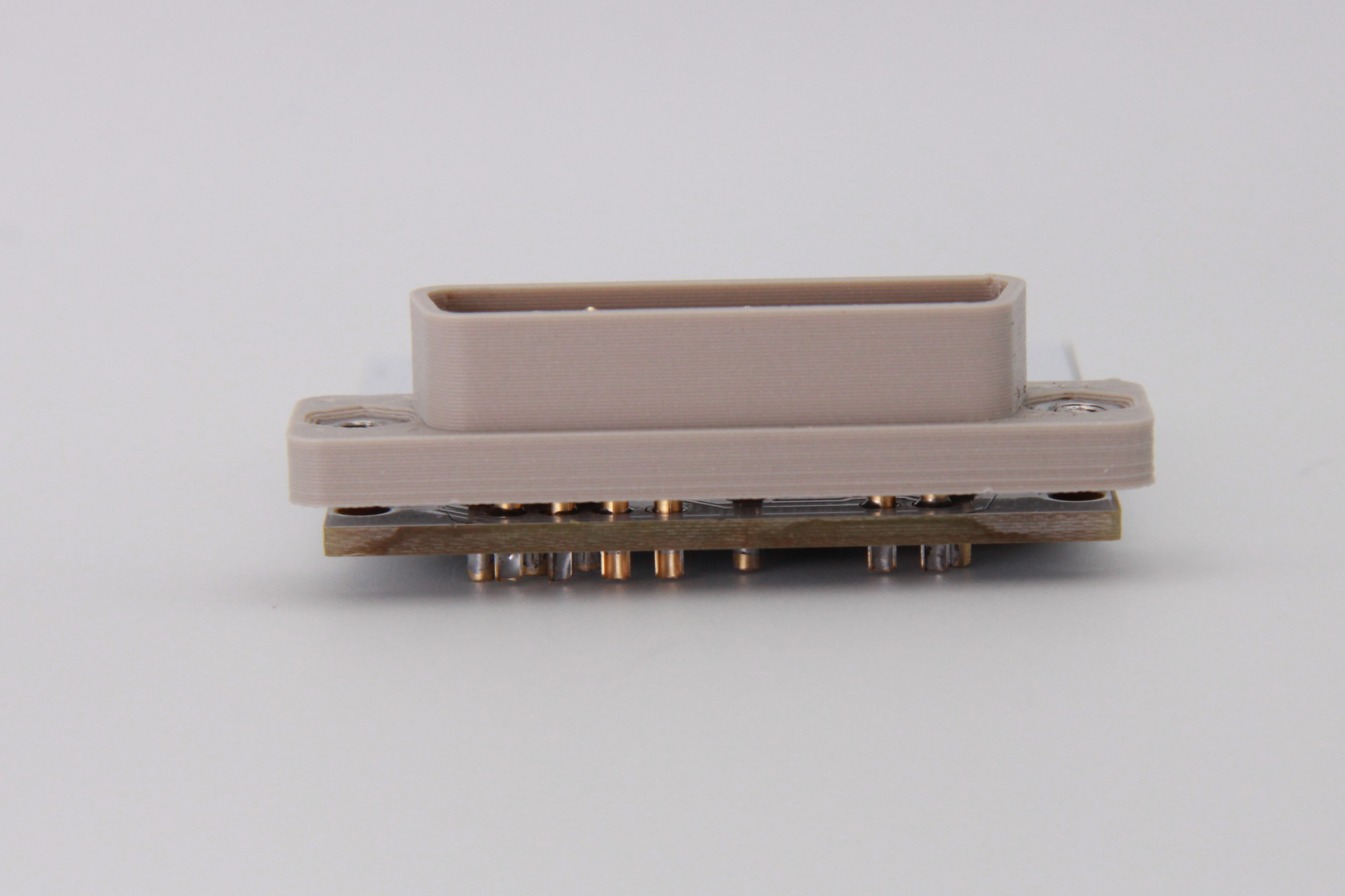
Press the light pipe into the LED opening with the lip side facing up and then slide the board in. If you can't slide the PCB under the light pipe, it is installed upside down. The side mounted LED's should keep the light pipe from falling out, even if it isn't a tight friction fit in the openings.
The ATmega328P is the same used on an Arduino Uno/Nano/Micro, but lacks the necessary bootloader firmware and serial interfaces to flash via the Arduino IDE or programs like XLoader. You could program the chip before installing it with something like a TL866/T48 and a TQFP32 to DIP 32 adapter, but I prefer to just use a cheap UBSASP and avrdude. Make sure you get a 10 pin to 8 pin adapter with the USBASP if it isn't natively an 8 pin model.
Since you didn't solder the 2x3 pin header on the ICSP port J2, you will need to hold the header pins at an angle in the holes to make contact while you run avrdude. If you're feeling fancy, you could spring for a 2x3 double row 2.54mm test clip or handheld pogo pin probe. The cheap angle method works fine for me.
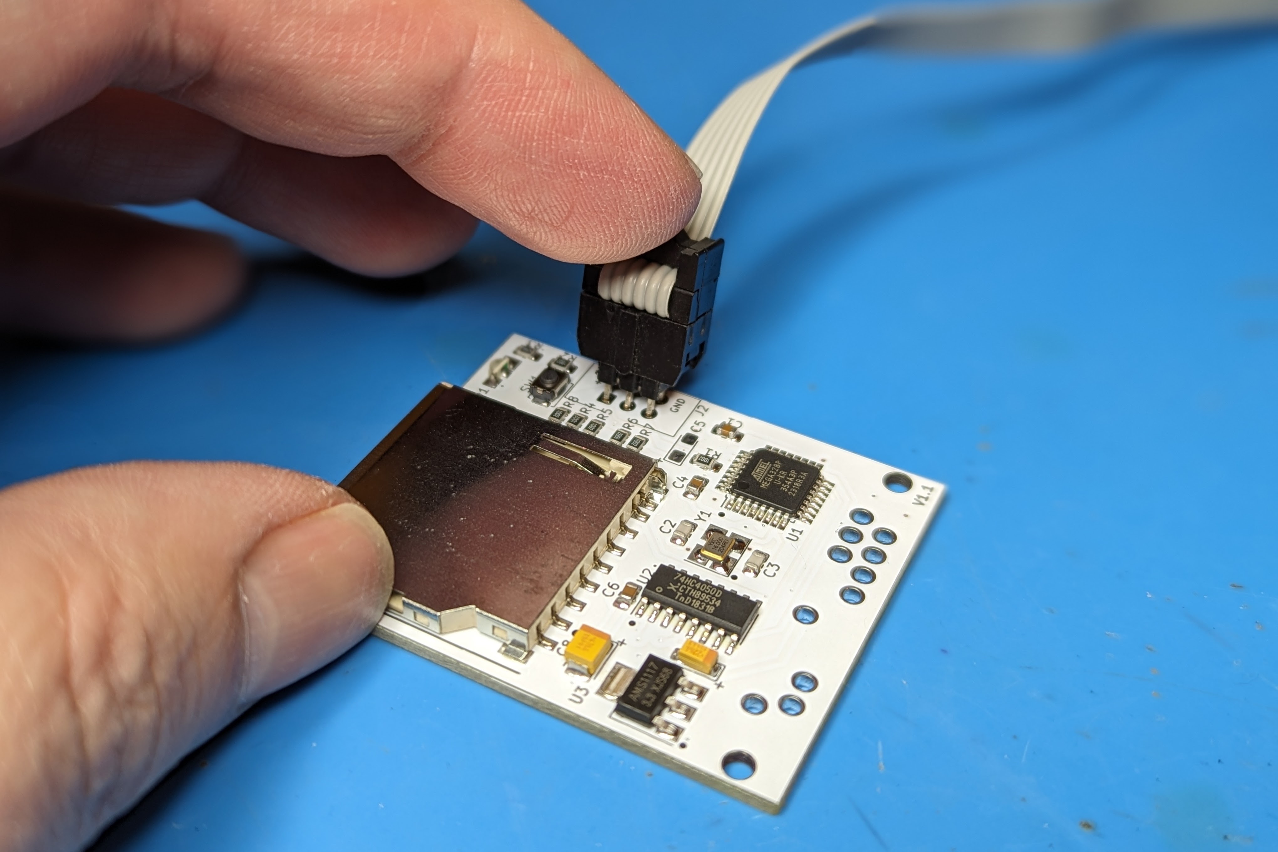
Since this model doesn't have the extra LED's to show the active partition, the firmware used is Katherine's standard version from https://gitlab.com/nyankat/smartportsd.
In my firmware directory there are couple of Windows scripts and a precompiled version of the SmartportSD firmware.
First you to need to setup your ATMega328p with the correct fuse setting so it uses the external 16 MHz crystal, same as an Arduino board. burn-328p-fuses.cmd executes the following:
avrdude -c usbasp -p m328p -B 125kHz -U lfuse:w:0xFF:m -U hfuse:w:0xDE:m -U efuse:w:0x05:m
Next flash SmartportSD-1.15.ino.with_bootloader.standard.hex with flash-smartportsd.cmd that executes:
avrdude -c usbasp -p m328p -u -U flash:w:SmartportSD-1.15.ino.with_bootloader.standard.hex
Plug into your Apple II and enjoy!
If you are in the US, PCB's are available from my Tindie store, https://www.tindie.com/products/tersteeg/smartportsd-apple-ii-pcb/
Otherwise, you can grab the gerbers and order from your favorite PCB fab.
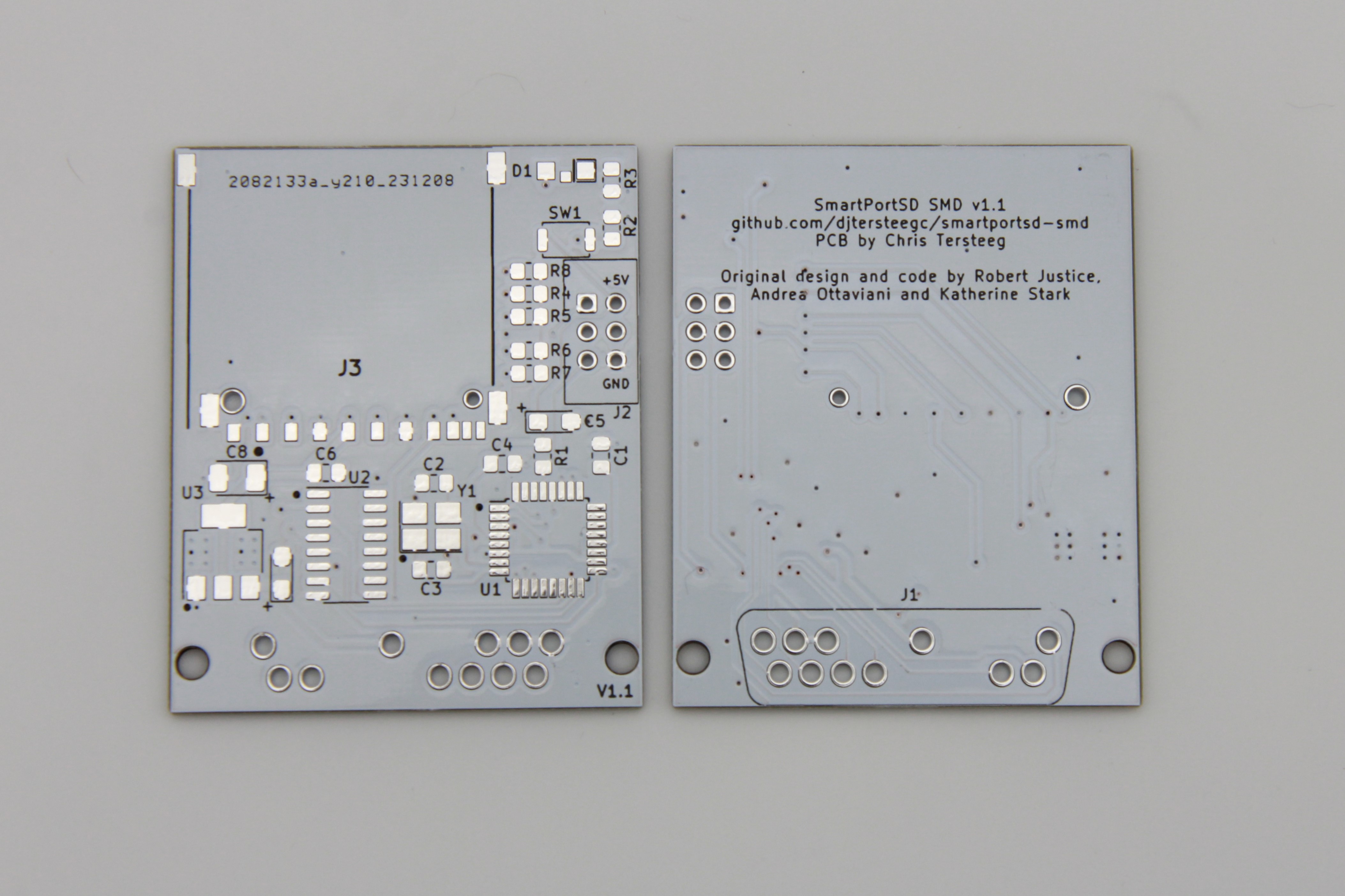
Worked but since it was pertty much a 1:1 copy of my TapecartSD base PCB, was just a little to wide to clear the composite video connector on an Apple IIc once cased.
Board was narrowed to allow needed clearance on IIc/c+ models.
| Qty | Value | Footprint | References |
|---|---|---|---|
| 7 | 10K | Resistor_SMD:R_0805_2012Metric_Pad1.20x1.40mm_HandSolder | R1, R2, R4, R5, R6, R7, R8 |
| 3 | 0.1uf | Capacitor_SMD:C_0805_2012Metric_Pad1.18x1.45mm_HandSolder | C1, C4, C6 |
| 2 | 18pf | Capacitor_SMD:C_0805_2012Metric_Pad1.18x1.45mm_HandSolder | C2, C3 |
| 2 | 22uf 10V | Capacitor_Tantalum_SMD:CP_EIA-3216-18_Kemet-A_Pad1.58x1.35mm_HandSolder | C5, C7 |
| 1 | 16MHz | Crystal:Crystal_SMD_3225-4Pin_3.2x2.5mm_HandSoldering | Y1 |
| 1 | 4050 | Package_SO:SOIC-16_3.9x9.9mm_P1.27mm | U2 |
| 1 | 470R | Resistor_SMD:R_0805_2012Metric_Pad1.20x1.40mm_HandSolder | R3 |
| 1 | 47uf 10V | Capacitor_Tantalum_SMD:CP_EIA-3528-12_Kemet-T_Pad1.50x2.35mm_HandSolder | C8 |
| 1 | AMS1117-3.3 | Package_TO_SOT_SMD:SOT-223-3_TabPin2 | U3 |
| 1 | ATmega328P-A | Package_QFP:TQFP-32_7x7mm_P0.8mm | U1 |
| 1 | DB19_Plug | Tersteeg:DSUB-19_Male_Vertical_P2.77x2.84mm_Narrow_MountingHoles | J1 |
| 1 | ICSP | Connector_IDC:IDC-Header_2x03_P2.54mm_Vertical | J2 |
| 1 | LED | Tersteeg:1204 Side Emitting LED | D1 |
| 1 | SD_Card_Push_Pull | TE SD Card 2041021-3:2041021-3_2 | J3 |
| 1 | SW_SPST | Button_Switch_SMD:SW_Push_SPST_NO_Alps_SKRK | SW1 |
djtersteegc/smartportsd
Various PCB and case designs of the SmartPortSD hard disk emulator for Apple II computers.

akuker/adbuino
Arduino-based USB keyboard and Mouse to ADB adapter. Allows USB keyboards and mice to be used with vintage Macintosh computers.

kvazimoda24/TionO2-ZigBee
Ядром проекта является микроконтроллер ATmega328P. Для работы по протоколу ZigBee используется модуль E18-MS1-PCB.

sherrardTr4129/RealSense-BNO055-Pose-Estimation
This repository contains required software to construct a Pose of a vision target by fusing its x,y,z coordinates from the Intel RealSense depth camera, with its quaternion orientation from the BNO055 sensor.

djtersteegc/tapecart-sd-vertical
Vertical SMD PCB design and 3D printable case of the TapeCart SD for the Commodore 64


d-diot/Mini-BT-Pcb-328P
MySensors ATMega328P + RFM69 and NRF24 battery (AAA and CR2032) powered pcb

spacebiz24/Thermal-Profiling
A Thermal Profiling Platform built with ATMega328P and MAX31856

It measures 41 × 50 mm and has 2 copper layers, 1.6 mm thick.
25 parts, built around the ATMEGA328P-AU and AMS1117-3.3. The full list of its parts is on this page, with links to each part's symbol and footprint where PCBKit's library has them.
From the djtersteegc/smartportsd repository on GitHub, at the commit this page was made from: the board is smartport-smd/smartportsd-smd.kicad_pcb and its schematic smartport-smd/smartportsd-smd.kicad_sch. PCBKit opens the board in the browser, with nothing to install.
Its repository publishes it under the MIT licence: you may reuse it on that licence's terms (keep the author's notice, and for a copyleft licence share your changes alike).