4 layers80 × 50 mm
Link teensy small
dg1vs/Transputer-Teensy-Link
A family of practical, Ethernet-connected link interfaces for classic INMOS transputer systems, based on the Teensy 4.1.
41 parts

 dg1vs/Transputer-Teensy-Link
A family of practical, Ethernet-connected link interfaces for classic INMOS transputer systems, based on the Teensy 4.1.
Link teensy is an open-source printed circuit board by dg1vs, from the dg1vs/Transputer-Teensy-Link repository on GitHub. It is a 4-layer board of 160 × 100 mm with 376 parts on 132 nets, routed with 1,303 tracks and 179 vias.
It is built around the SN74LVC1G06DBV, TEENSY 4.1 and TXU0202DCU, with the SN74LXC8T245PW, 74HC74D and TXU0102 among its other parts. Its parts include 20 capacitors, 16 resistors, 16 ICs, 7 connectors and 5 diodes. It belongs with the NXP (LPC, Kinetis, i.MX RT) boards of this library.


A family of practical, Ethernet-connected link interfaces for classic INMOS transputer systems, based on the Teensy 4.1.
The project provides three hardware variants, a common firmware platform, and compatibility with host tools using the INMOS B300/TCPlink protocol.
Project status: All three interfaces are in active use. They are experimental retrocomputing hardware and may still contain minor hardware or firmware quirks. Enclosures have not yet been designed.
Transputers remain fascinating devices even in 2026.
They combine a processor, local memory, hardware-assisted process scheduling, and fast point-to-point communication links. A transputer was intended to be used as a building block in a larger network of cooperating processors rather than as the single centre of a computer.
Together with occam and its CSP-inspired programming model, transputers provide a very direct platform for studying:
Many of these ideas are still relevant in modern many-core processors, network-on-chip architectures, distributed services, and accelerator systems.
The difficult part today is often not finding an interesting transputer board. The practical problem is finding a convenient interface between a modern computer and the transputer link.
A useful modern transputer link interface should ideally be:
The use of Ethernet provides a standard host connection and, with normal Ethernet magnetics, galvanic isolation between the host network and the adapter.
The current transputer-side interfaces are single-ended and share their electrical reference with the target system. Full galvanic isolation of the transputer link itself is therefore a possible future improvement rather than a feature of the current boards.
Andre Saischowa created the first prototype using a Teensy 4.1 together with an INMOS C011 link adapter.
The article Putting A Teensy To Task As A Transputer Link described how the Teensy 4.1 UART can implement the unusual transputer link framing directly. This led to a substantial extension of the firmware and made it possible to operate a transputer link without a C011.
Karsten Schmidt, DG1VS, designed the printed circuit boards. Andre is the author and maintainer of the Teensy Link software and continued to develop and improve the firmware.
The result is a common software platform supporting both the traditional C011 approach and direct Teensy-to-transputer communication.
flowchart LR
    HOST["Host computer<br/>Linux, macOS, Windows, ..."]
    ETH["Ethernet / TCP/IP<br/>B300-compatible Linkops service"]
    T41["Teensy 4.1"]
    PHY["C011 or direct<br/>transputer link"]
    TARGET["Transputer system"]

    HOST <--> ETH
    ETH <--> T41
    T41 <--> PHY
    PHY <--> TARGET
The firmware obtains its IP address using DHCP and provides a B300-compatible service on TCP port 4047.
The current firmware also contains:
The additional USB and audio functions are not required for normal B300 link operation.
The KiCad hardware projects are located below hardware/.
link_teensy — C011 and direct Teensy LinkDirectory: hardware/link_teensy/
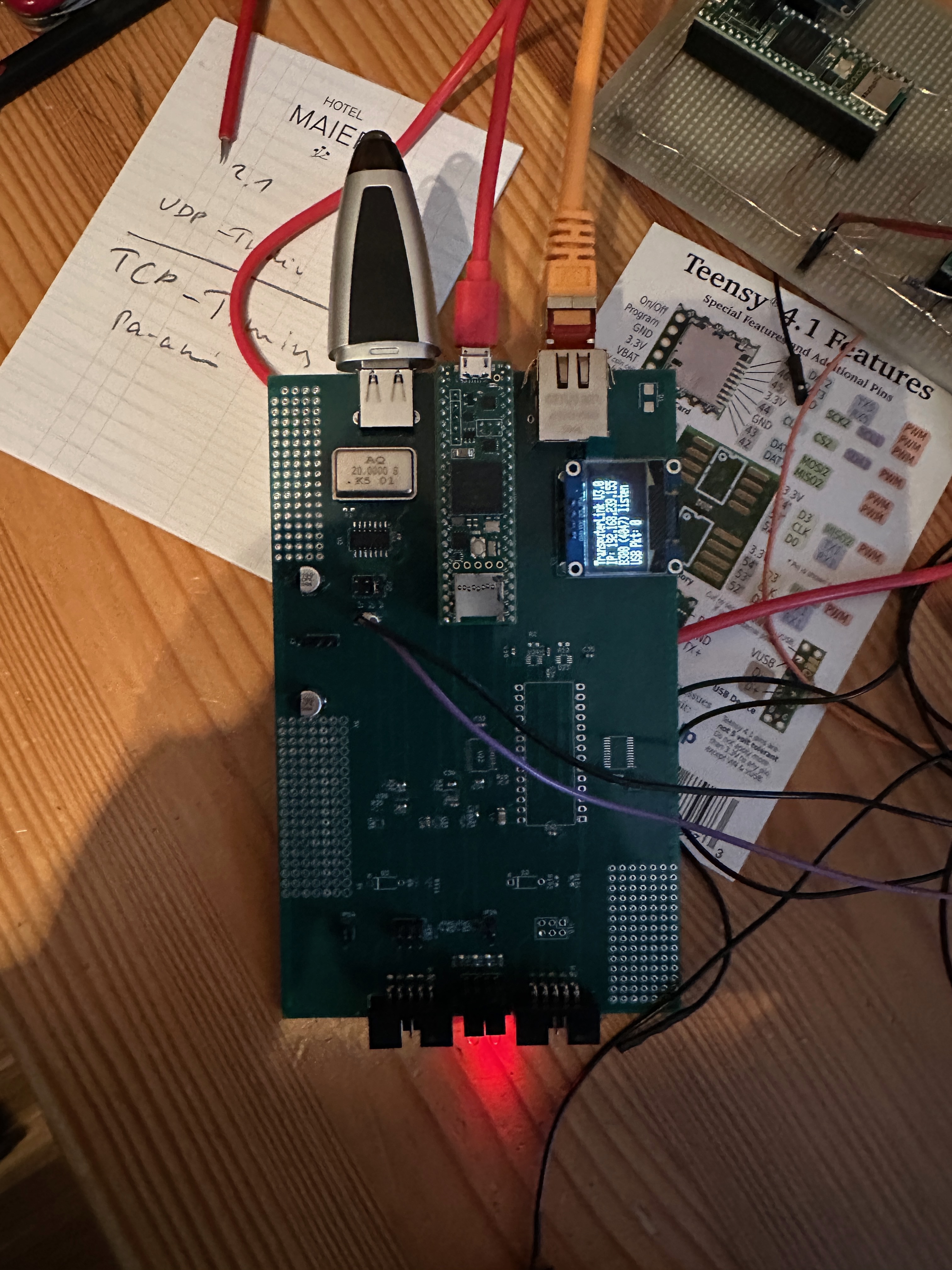
This is the most complete board and contains both:
flowchart LR
    HOST["Ethernet host"] <--> T41["Teensy 4.1"]
    T41 --> C011["INMOS C011"]
    T41 --> DIRECT["Direct Teensy Link"]
    C011 --> TARGET["Transputer system"]
    DIRECT --> TARGET
This board is useful as:
The main disadvantage of the C011 path is its dependency on a historical component that is increasingly difficult to obtain.
link_teensy_small — compact direct linkDirectory: hardware/link_teensy_small/
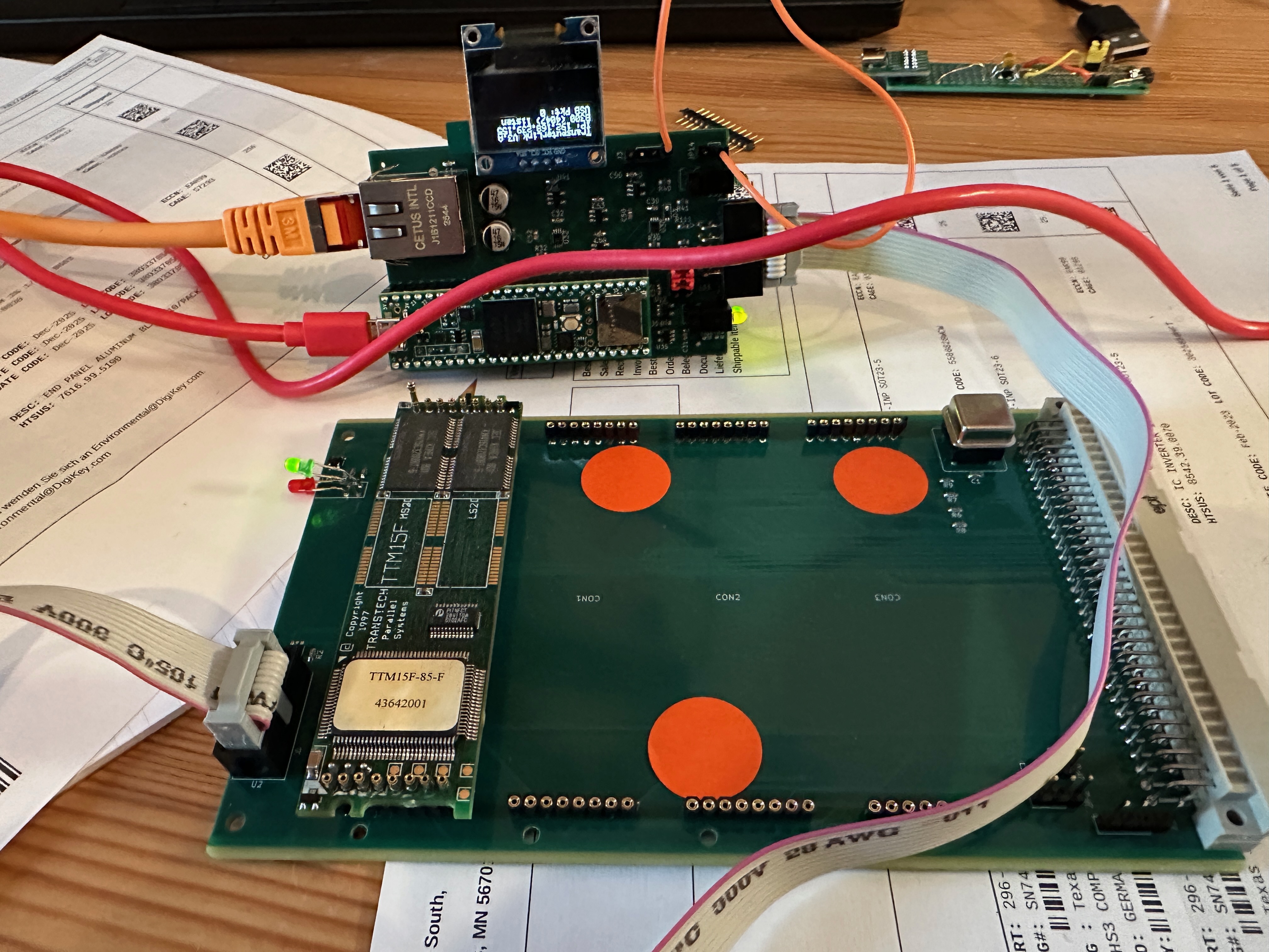
This is a smaller board that connects the Teensy 4.1 directly to the transputer link without requiring a C011.
flowchart LR
    HOST["Ethernet host"] <--> T41["Teensy 4.1"]
    T41 <--> TARGET["Transputer system"]
This is currently the most frequently used interface.
Its advantages include:
The target connector includes:
LinkInLinkOutnotResetnotAnalysenotErrorAlways verify the exact connector orientation and board revision before connecting a target.
link_teensy_fpga — direct link with PMOD adapterDirectory: hardware/link_teensy_fpga/
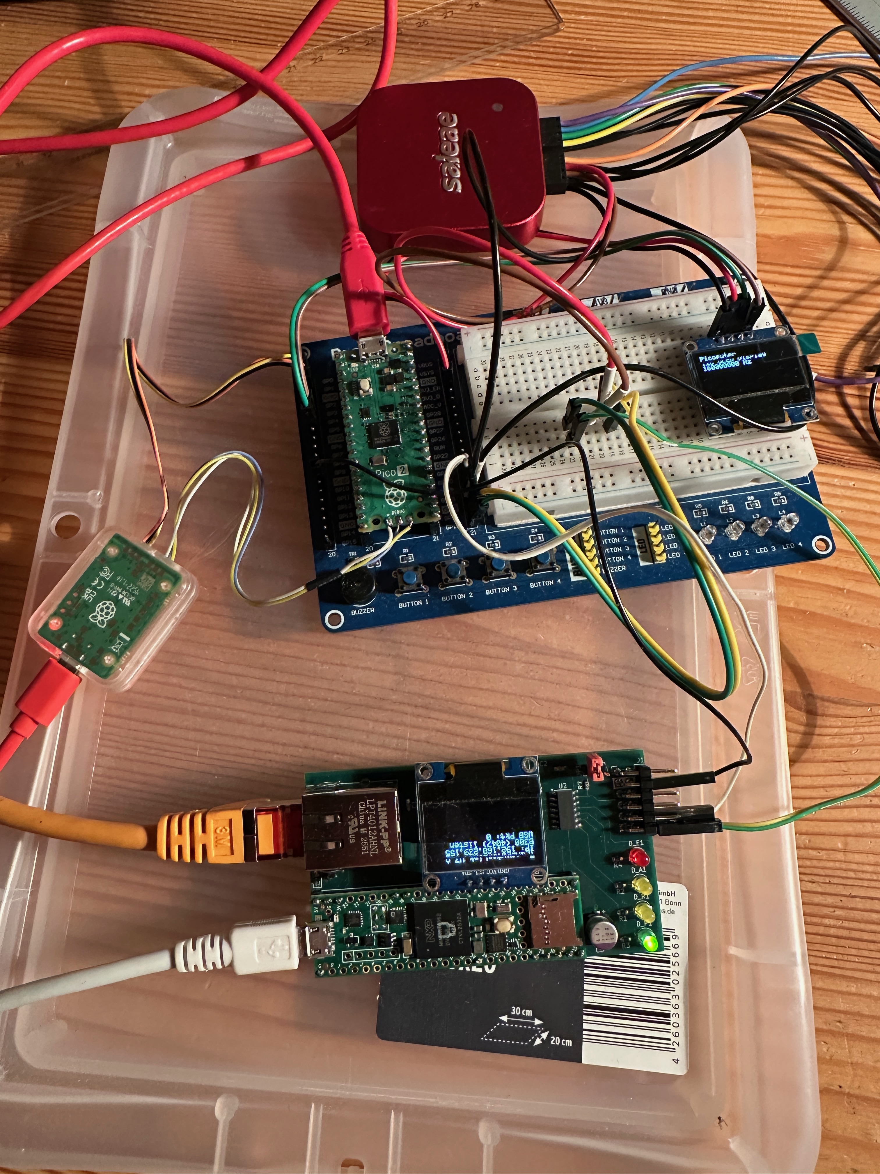
This version is derived from the compact direct-link design and adds a 12-pin PMOD-style connector.
It is currently used while developing the Transputer Picoputer.
flowchart LR
    HOST["Ethernet host"] <--> T41["Teensy 4.1"]
    T41 <--> PMOD["PMOD adapter"]
    PMOD <--> PICOPUTER["Transputer Picoputer"]
The PMOD mapping documented in the schematic is:
| Transputer signal | PMOD pin | Transputer signal | PMOD pin |
|---|---|---|---|
LinkIn | 1 | LinkOut | 7 |
notAnalyse | 2 | notReset | 8 |
| — | 3 | notError | 9 |
| — | 4 | — | 10 |
| GND | 5 | GND | 11 |
| 3.3 V | 6 | 3.3 V | 12 |
This variant is intended for development systems that expose their transputer-style link through a PMOD-compatible connector.
The INMOS transputer link protocol resembles asynchronous serial communication, but it is not a conventional UART protocol.
Two token types are used:
The Teensy 4.1 UART provides two features that make a direct implementation possible:
The additional UART bit is used to reproduce the special transputer data-token framing. Incoming words are decoded as either data or acknowledgements, and the firmware implements the required link-level handshake and buffering.
The current direct-link implementation supports:
The firmware deliberately rejects 10 Mbit/s and recommends 20 Mbit/s. At the maximum speed, a timing corner case involving the emulated acknowledgement and a very fast response to operations such as PEEK is avoided.
The direct-link implementation currently uses:
| Function | Teensy 4.1 resource |
|---|---|
| Link UART | Serial7 |
| Receive | pin 28 |
| Transmit | pin 29 |
| Target reset | pin 30 |
| Target analyse | pin 31 |
| Target error | pin 32 |
These assignments are defined in firmware/teensy_audiomidi_c011/tplinkconf.h.
The original INMOS IMS B300 TCPlink system provided network access to transputer links over Ethernet and TCP/IP.
This project implements the relevant Linkops service used by B300-compatible host drivers. The implemented operations include:
The firmware identifies the service as:
inmos.com(tcplink-linkops-01.00)The B300-compatible server listens on the standard TCP port:
4047Technical documentation for the original system is available from transputer.net:
Modern builds of classic transputer host tools and the link300 driver are provided by Michael through transputer.net:
Michael is the owner and maintainer of the tools distributed through transputer.net. These host tools are separate from the Teensy Link firmware in this repository.
Packages are available for several systems and architectures, including:
Depending on the platform, the archive contains tools such as:
iserverafserverlinktestpeekpokerspyanalyselink300 library or DLLThe software/ directory contains project notes. For current binaries, use the transputer.net archive directly and observe its licensing and redistribution conditions.
The main firmware is located in:
firmware/teensy_audiomidi_c011/
A separate pin-test sketch is located in:
The checked-in tplinkconf.h currently enables:
0x3c.The C011 backend is present but disabled in the default configuration.
For the direct Teensy Link:
//#define MIT_LINK_C011
#define MIT_LINK_TEENSY
For the C011 backend, enable MIT_LINK_C011 and configure the other options according to the connected hardware.
The firmware can contain both backends, but their exact routing behaviour depends on the selected compile-time options. Review tplinkconf.h before building.
The firmware is intended for a Teensy 4.1 using the Arduino IDE with Teensy support.
Install the following:
NativeEthernet;LibPrintf;Adafruit GFX Library;Adafruit SSD1306.The Teensy core USB host library is used by the optional USB host functions.
The direct transputer link requires 9-bit UART support in the Teensy core.
Locate HardwareSerial.h in the installed Teensy 4 core and enable:
#define SERIAL_9BIT_SUPPORTThe firmware checks for the resulting 9-bit inverted-UART definitions and stops compilation with an explanatory error when they are unavailable.
This modification may need to be repeated after updating the Teensy board package.
The checked-in configuration enables the USB MIDI client code. Select an Arduino USB type that provides both Serial and MIDI, or disable MIT_USBMIDI_CLIENT in tplinkconf.h.
Open:
firmware/teensy_audiomidi_c011/teensy_audiomidi_c011.inoSelect Teensy 4.1 as the target board.
Review tplinkconf.h.
Compile and upload the sketch.
Connect Ethernet.
Open the serial monitor or read the optional OLED display.
The adapter uses DHCP and reports its assigned IP address through the serial console and OLED display.
The serial startup message also shows:
The exact setup depends on the operating system and the downloaded link300 driver.
A typical Linux example is:
export TRANSPUTER="$HOME/bin/transputer/link300.so.1.0.1@192.168.1.123"Replace:
192.168.1.123 with the IP address shown by the adapter.You can then test the connection using tools such as:
linktestor inspect a connected network with:
rspyTo boot a transputer program:
iserver -sb program.btlTool names, options, and library filenames vary slightly between operating systems and architectures.
Only one B300 client should normally control the adapter link at a time.
| Port | Function |
|---|---|
4047/tcp | B300-compatible Linkops service |
4040/tcp | experimental network throughput test |
80/tcp | simple status and monitoring web page |
The status page can be opened in a browser using the adapter IP address:
http://192.168.1.123/The web page is a development monitor, not a hardened management interface. The adapter should therefore be used on a trusted local network.
Transputer-Teensy-Link/
├── docs/
│   └── README.md
├── firmware/
│   ├── teensy_audiomidi_c011/
│   ├── teensy_pin_test/
│   └── README.md
├── hardware/
│   ├── docu_extern/
│   ├── libs/
│   ├── link_teensy/
│   ├── link_teensy_small/
│   ├── link_teensy_fpga/
│   └── README.md
├── software/
│   ├── README.md
│   └── bin.zip
├── .gitmodules
└── README.md
The KiCad projects use the external Transputer KiCad Library as a Git submodule.
Clone the project with submodules:
git clone --recurse-submodules git@github.com:dg1vs/Transputer-Teensy-Link.gitFor an existing clone:
git submodule update --init --recursiveThe hardware files are current KiCad 9 projects.
The interfaces are working development tools, but the following points remain:
Before applying power:
LinkIn and LinkOut;notReset, notAnalyse, and notError;VIN and VUSB.Classic transputer hardware is increasingly difficult to replace. Test new cables and boards with current-limited supplies before connecting valuable systems.
Feedback, documentation improvements, test reports, and fixes are welcome.
A useful issue report should include:
tplinkconf.h;link300 version;This is an experimental retrocomputing project and is provided without warranty. Verify all electrical characteristics before connecting the adapter to valuable or irreplaceable hardware.
| Qty | Value | Footprint | References |
|---|---|---|---|
| 17 | 0.1µF | Capacitor_SMD:C_0603_1608Metric_Pad1.08x0.95mm_HandSolder | C1, C30, C31, C32, C33, C34, C35, C50, C51, C52, C53, C54, C55, C56, C57, C58 +1 |
| 9 | 10k | Resistor_SMD:R_0603_1608Metric_Pad0.98x0.95mm_HandSolder | R1, R2, R9, R10, R11, R12, R30, R32, R102 |
| 6 | SN74LVC1G06 | Package_TO_SOT_SMD:SOT-353_SC-70-5 | U33, U34, U35, U40, U41, U42 |
| 3 | 2x3 | Connector_PinHeader_2.54mm:PinHeader_2x03_P2.54mm_Vertical | J10, J11, J20 |
| 3 | 470 | Resistor_SMD:R_0805_2012Metric_Pad1.20x1.40mm_HandSolder | R41, R42, R43 |
| 3 | TXU0202 | Package_SO:VSSOP-8_2.3x2mm_P0.5mm | U23, U24, U30 |
| 2 | 100µF | Capacitor_SMD:CP_Elec_5x3.9 | C300, C500 |
| 2 | 1N4148 | Diode_THT:D_A-405_P7.62mm_Horizontal | D2, D3 |
| 2 | 56 | Resistor_SMD:R_0603_1608Metric_Pad0.98x0.95mm_HandSolder | R101, R111 |
| 2 | Jumper_2_Open | Connector_PinHeader_2.54mm:PinHeader_1x02_P2.54mm_Vertical | JP14, JP24 |
| 2 | SN74LXC8T245 | Package_SO:TSSOP-24_4.4x7.8mm_P0.65mm | U21, U22 |
| 2 | ~ | Connector_IDC:IDC-Header_2x05_P2.54mm_Horizontal | L10, L11 |
| 2 | ~ | Transputer:mentor_LED_2 | LED1, LED2 |
| 1 | 1k | Resistor_SMD:R_0603_1608Metric_Pad0.98x0.95mm_HandSolder | R35 |
| 1 | 1µ | Capacitor_SMD:C_1206_3216Metric_Pad1.33x1.80mm_HandSolder | C2 |
| 1 | 500 | Resistor_SMD:R_0805_2012Metric_Pad1.20x1.40mm_HandSolder | R40 |
| 1 | 74HC74 | Package_SO:SO-14_5.3x10.2mm_P1.27mm | U2 |
| 1 | CXO_DIP8_14 | Transputer:Oscillator_DIP-8_14 | Y1 |
| 1 | Clock | Connector_PinHeader_2.54mm:PinHeader_1x02_P2.54mm_Vertical | J4 |
| 1 | DM-OLED096-636 | Transputer:MODULE_DM-OLED096-636 | U3 |
| 1 | D_Schottky_Small | Diode_SMD:D_SMB | D1 |
| 1 | IMSC011Mode1 | Package_DIP:DIP-28_W15.24mm_LongPads | U20 |
| 1 | J1B1211CCD | Transputer:J1B1211CCD | P1 |
| 1 | MP_Power | Connector_PinHeader_2.54mm:PinHeader_1x04_P2.54mm_Vertical | J3 |
| 1 | TXU0102 | Package_SO:VSSOP-8_2.3x2mm_P0.5mm | U32 |
| 1 | Teensy4.1 | Transputer:Teensy41 | U1 |
| 1 | USB_A | Transputer:USB_A | J1 |
The 69 most common of 376 parts.
dg1vs/Transputer-Teensy-Link
A family of practical, Ethernet-connected link interfaces for classic INMOS transputer systems, based on the Teensy 4.1.

dg1vs/Transputer-Teensy-Link
A family of practical, Ethernet-connected link interfaces for classic INMOS transputer systems, based on the Teensy 4.1.

dg1vs/Transputer-TRAM-TangNano
A TRAM-size FPGA Transputer module based on the Sipeed Tang Nano 20K.

gavin4d/PPG-Watch
Smart watch with a photoplethysmography analog front end and e-paper display


Electro707/p1200_lcd_backpack
My version of an LCD Backpack with some unique features


dg1vs/Transputer-Base-Board
This project is a 4-TRAM Transputer Base-Board. TRAMs are small subassemblies of transputers (or other components with INMOS links), a few discrete components, and sometimes some RAM and/or application specific…
It measures 160 × 100 mm and has 4 copper layers, 1.6 mm thick.
376 parts, built around the SN74LVC1G06DBV, TEENSY 4.1, TXU0202DCU and SN74LXC8T245PW. The full list of its parts is on this page, with links to each part's symbol and footprint where PCBKit's library has them.
From the dg1vs/Transputer-Teensy-Link repository on GitHub, at the commit this page was made from: the board is hardware/link_teensy/link_teensy.kicad_pcb and its schematic hardware/link_teensy/link_teensy.kicad_sch. PCBKit opens the board in the browser, with nothing to install.
Its repository states no licence, so its author keeps all rights: ask dg1vs before reusing the design.